Flexwatch FWR303-00N User manual

NVR
R3 Series
FWR303-00N / FWR303-04P / FWR303-08P
User Manual
ver.1.1 / 2014.1

1
FCC Compliance Statement
Model Name: FWR303-00N / FWR303-04P / FWR303-08P
This device complies with Part 15 of the FCC Rules. Operation is Subject to the following two conductions: (1)
this device may not cause harmful interference, and (2) this device must accept any interference received,
including interference that may cause undesired operations.
WARNING
Unauthorized reproduction of all or part of this manual is strictly prohibited.
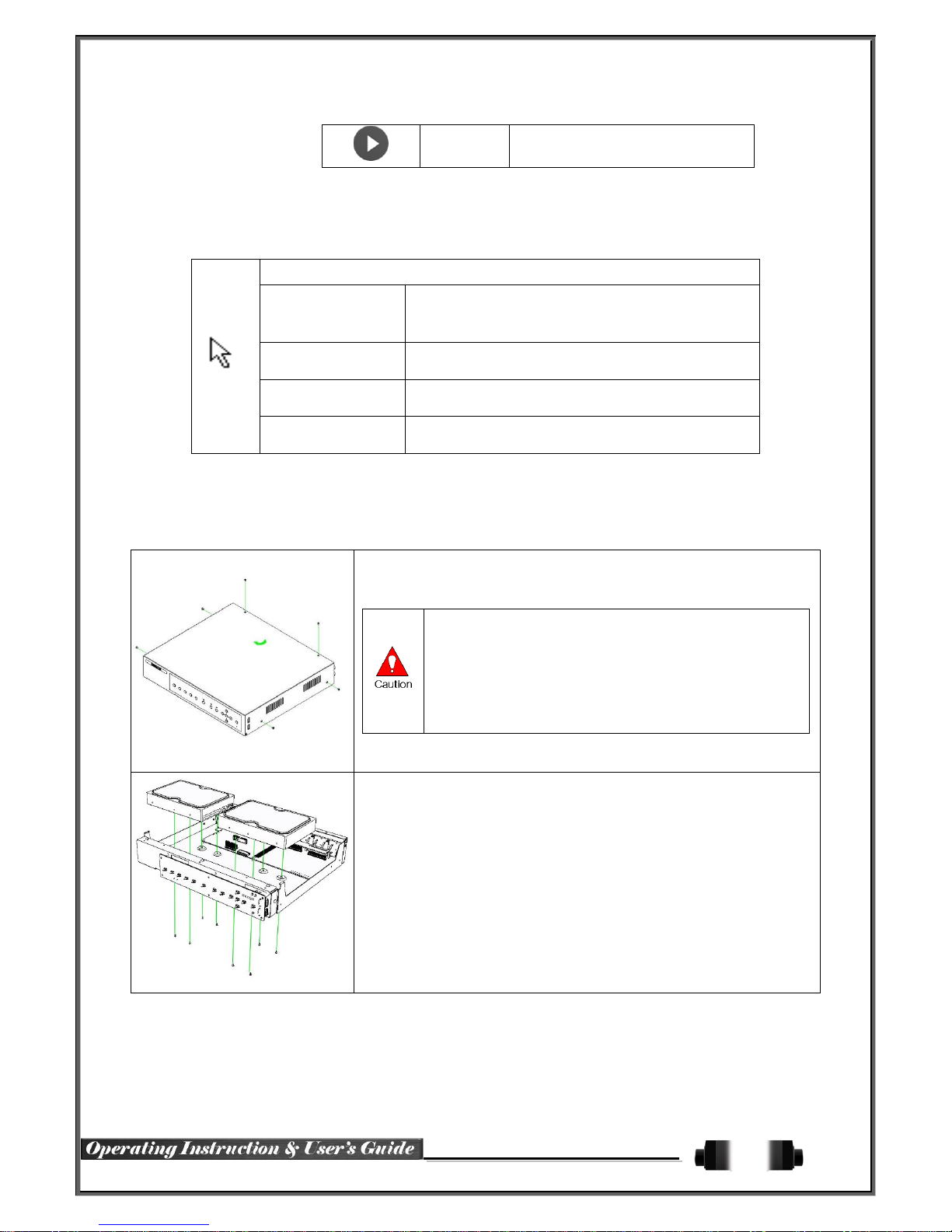
The figures in this manual are for illustration purposes only (may differ from the actual product).
The specifications and design of the product are subject to change without prior notice for purposes of quality
improvement.
CAUTIONS
To get the best use out of the product, be sure to read the cautions before using the product.
For safety, please take note of the following.
Instructions before using the product
1 To prevent electric shock when installing, moving, or opening the NVR and peripheral devices, connect
and disconnect the cables as instructed. All cables must be connected to grounded power outlets.
2 If the product is installed near a power outlet, make sure it can be unplugged easily.
3 Do not use the NVR in water or in wet places.
4 Keep the plastic packing materials used for the NVR or other peripheral devices out of reach of children
(may cause suffocation).
Installation Environment of the NVR
1 Maintain the following conditions: operating temperature of 5˚C ~ 40˚C; operating humidity of 10% ~ 80%.
2 Install the NVR in a safe place that is free from external vibration.
3 Install the NVR in a well-ventilated place.
4 To protect the hard disk from data loss and breakdown, install the NVR away from magnetic materials.
5 When using a rack other than the standard one, use a separate table with sufficient spacing, i.e., 60cm
from the floor, 50cm from the ceiling, and 20cm from the side and back walls and other objects.
Safety Notes on the NVR
1 When installing additional boards and HDD, separate the power cable and turn OFF power supplied to the
NVR completely..
2 Keep the product away from heat-generating devices such as heaters.
3 Do not use a damaged power cord.
4 To prevent problems due to magnetic interference and electric surge, use only grounded cables and
power outlets.
5 If the power cord is connected, do not touch the power unit. If the power cord is connected, electric current
is still flowing internally even after the switch is turned OFF.
6 Do not place a heavy object on top of the product.
7 Do not drop a conductive object in the ventilation holes.
8 Allot sufficient space for system cabling.
9 Use only the parts indicated in the manual. Do not disassemble, repair, or modify the product without
permission.
10 Incorrect system setup may cause malfunction.
11 Shut down the system normally as instructed in the manual.
Safety Notes on the Lithium Battery
1 Replace lithium batteries as instructed to avoid danger.
2 Dispose used lithium batteries properly.

2
【Warning and Caution are indicated as follows.】
Possible injury or product damage.
Risk of minor injury or product damage.
Cautions for the usage of the product.
Information for the usage of the product.

3
Chapter 1. Introduction................................................................. 4
1-1NVR Model Major Features .....................................................................4
1-2Components ........................................................................................5
Chapter 2. Installation & Device Connection................................... 6
2-1NVR series Front Panel ..........................................................................6
2-2NVR series Rear....................................................................................6
2-3Configuration Switch Setup ....................................................................7
2-4Terminal Block .....................................................................................7
Chapter 3. Operation, Setup Tools................................................ 8
3-1Remote Controller .................................................................................8
3-2Mouse.................................................................................................9
Chapter 4. NVR Operation Setup .................................................. 9
4-1Storage Installation ...............................................................................9
4-2Network Setup.................................................................................... 10
4-3IP Camera Registration & PoE port connection ....................................... 11
4-3-1 Non PoE model.................................................................................. 11
4-3-2 NVR with PoE port .............................................................................. 12
4-4Monitoring ......................................................................................... 13
4-5Playback ........................................................................................... 18
4-6Setup ................................................................................................ 20
4-7Search .............................................................................................. 36
4-8Backup.............................................................................................. 38
Chapter 5. Miscellaneous .......................................................... 42
5-1Miscellaneous .................................................................................... 42
A/P/P/E/N/D/I/X........................................................................... 46
Recommended HDD Specification .................................................................... 46
Recommended USB2.0 Devices....................................................................... 46

4
Chapter 1. Introduction
1-1NVR Model Major Features
Line Up
NVR
Model Name
FWR303-00N / FWR303-04P/ FWR303-08P
System
OS
Embedded Linux - Built in flash memory
Access
Mouse, Remote Controller, Network, Key controller
Hexaplex
Live monitoring, Recording, Playback, Backup, Network, Setup
Upgrade
USB2.0 Memory stick, Network
Camera
IP Camera
ONVIF
Video
System
NTSC / PAL - Config switch
Input
Up to 16 Channel
Display Rate
Max. 120 / 100 fps
Output
1 HDMI, 1 VGA, 1 BNC
Audio
Input / Output
Interface
16 IPC / HDMI
Video
Recording
Compression
H.264
Speed
Max. 1080p 120
Resolution
1080p, 720p
Event
Motion, Sensor
Bit Rate
Max. 8Mbps / Channel
Playback
Search
Go to first rec. time, Go to last rec. time, Go to last search time, Calendar,
Log viewer, Smart search, Multi-time & Multi day search, Event search
Mode
Event only playback, Backward, Pause, Frame by frame,
Speed up ( x1 ~ x32, x300)
Network
Interface
Ethernet 10 / 100 / 1G
Compression
H.264 / JPEG
Speed
Max. D1 10fps / Channel
Resolution
Max. 1080p
Backup
Interface
USB2.0, Network
Format
Video clip (Backup viewer), JPEG Still Image, Log list, Setup data
Alarm
Pre/Post-Alarm
5sec / 5sec~5min
Motion Grid
14 x 15 (NTSC / PAL)
Alarm Action
E-mail, Channel Popup, Buzzer, Relay, PTZ Preset, Remote CMS, Front
LED
Input / Output
4 / 1 –NC / NO / EOL
Display
HDMI / VGA
Full HD
TV
SDTV(720 x 480 / 576)
Mode
16 / 9 / 4 / 1 / SEQ - LIVE, 16 / 9 / 4 / 1 - P.B
External
Interface
PTZ / Keyboard
★2 RS485 - Terminal Block
ATM / POS
★RS232C - Terminal Block

5
Storage
Primary
2 HDD
External
1 e-SATA
ODD
N/A
Features
EOL Register(10K)
★4Ch
Digital Zoom
x1 ~ x16
Watermarking
Yes
Detection / Search
Motion, Sensor
Fan Fail
Yes
E-mail
5 User with still image
Capture
1080p
iSCS Recording
Yes
DDNS, DHCP, UPNP
Yes
CMS, VMS, RMS
Windows
Smart Phone (3G)
Android, iPhone, iPad
Mac Viewer
★Apple Mac OS
General
Power Supply
12V/5A - Level 5
Consumption
60Watts
PoE Consumption
FWR303-08P : 48V 2A FWR303-04P : 48V 1A
Operation Temp /
Humidity
5 ~ 40 ℃/ 10 ~ 80%
Dimension
340 x 59 x 300 mm
Certification
CE, FCC, RoHS Compliance
1-2Components
After unpacking the product, check whether following accessories are included.
- Remote Controller
- CD (CMS, CMS Manual, User Manual)
- AAA 1.5V Batteries 2ea
- Adapter (DC 12V / 5A)
- PoE Power Adaptor (PoE model) –FWR303-04P (DC 48V 1A) FWR303-08P(DC 48V 2A)
FWR303-04P: Up to 30w for each channel, total Max. 40w (IEEE 802.3at);
FWR303-08P: Up to 30w for each channel, total Max. 80w (IEEE 802.3at);

6
Chapter 2. Installation & Device Connection
2-1NVR series Front Panel
No.
Name
Feature
1
USB Port
USB Mouse, USB Memory Stick Connection Port
2
LABEL
Brand Name and Model Name
3
POWER LED RECORD LED
LED indicating Power On/Off
4
RECORD LED
Blue LED turned on upon HDD operation.
2-2NVR series Rear
No.
Name
Feature
Type
1
e-SATA
External SATA
USB Type A, e-SATA
2
TV
CCTV monitor displays the output images.
BNC
3
HDMI
HDMI Output
HDMI type-C
4
VGA-OUT
VGA Monitor or LCD Monitor Connection
D-SUB 15P
5
Ethernet
Cable Modem, Ethernet 10/100 Base-T, Network Connection
RJ-45
6
Terminal Block
RS-485 / SENSOR IN / RELAY OUT / POS
Terminal Block
7
CONFIG
NTSC/PAL , HD / XGA
DIP S/W, 2-pin
8
Power
DC 12V 5A 60 Watts
DC Jack

7
No.
Name
Feature
Type
1
PoE Power
FWR303-04P: DC 48V 1A
FWR303-08P: DC 48V 2A
DIN Jack
2
PoE Port
IP Camera Connection
RJ-45
3
Audio In
Audio input
RCA
4
Audio Out
Audio Output
RCA
5
e-SATA
External SATA
USB Type A, e-SATA
6
TV
CCTV monitor displays the output images.
BNC
7
HDMI
HDMI Output
HDMI type-C
8
VGA-OUT
VGA Monitor or LCD Monitor Connection
D-SUB 15P
9
Ethernet
Cable Modem, Ethernet 10/100 Base-T, Network Connection
RJ-45
10
Terminal Block
RS-485 / SENSOR IN / RELAY OUT / POS
Terminal Block
11
CONFIG
NTSC/PAL , HD / XGA
DIP S/W, 2-pin
12
Power
DC 12V 5A 60Watts
DC Jack
2-3Configuration Switch Setup
Switch 2
2-4Terminal Block
The terminal blocks in the rear of the product are for the connection of PTZ / Sensor / Relay / POS Connection.
The number of the terminal block may be different depending on the model.
①PTZ Camera/Keyboard Controller
Connect PTZ control cable; TRX+, TRX- and GND to Terminal Block (TB1); No.4 TRXD+, No.5 TRXD- and No.10
GND in the rear of NVR. You may refer to APPENDIX for supported PTZ cameras in this manual. Keyboard

8
controller has the same connection as PTZ camera.
②Sensor / Relay / POS
Connect Sensor / Relay / POS to the terminal block directly depending on the model.
Sensor and Relay Type
NC(Normal Close) : Normally closed; opens when a signal is received
NO(Normal Open) : Normally open; closes when a signal is received
The external alarm device may require the power supply depending on its type.
Be cautious.
Chapter 3. Operation, Setup Tools
NVR Model can be controlled easily by using the front panel, remote controller and mouse.
3-1Remote Controller
POWER
Turn the system power
ON or OFF.
MODE
FULL
1CH Mode
QUAD
4CH Mode
9 SPLIT
9CH Mode
16 SPLIT
16CH Mode
SEQ.
Sequence Mode ON/OFF
B) System Operation and Setup Button
MENU
Data, Schedule, System Set up
ESC
Exit the current menu
Move to the upper menu.
PREV
Move back (Reverse)
PAUSE
Pause
FORWARD
Move forward
BACKWAR
D
Playback

9
PLAY
Play
3-2Mouse
The mouse pointer as shown below appears if a mouse is connected to the USB terminal at the front panel.
Mouse Control functions are shown below.
Click on the right
button
Monitoring Mode / Move from Play Mode to Monitoring
Menu / Pop up or remove Play Menu.
Show sub-folder of the certain Menu window.
Click on the left
button
Select Menu.
Double click on the
left button
Select Menu.
Click the left button
and drag
Move a certain window.
Chapter 4. NVR Operation Setup
4-1Storage Installation
1) 1) Open the top case by using screw driver.
1) Normal termination of the system and fully unplugged power
code are required before conducting HDD installation.
2) Touch a grounded metal substance or ground yourself
before installing HDD in order to reduce static electricity. Static
electricity may cause a malfunction of the product.
3) After installing HDD, Do not connect to power supply with the
top case opened. The top case must be covered before usage.
2) Unscrew and separate the HDD bay from body.
3) Screw the additional HDD bay to current HDD bay
4) Connect HDD to HDD connector on the main board directly without cable.
Reassemble the top case by reversing 1) to finalizing HDD installation.

10
4-2Network Setup
Connect the NVR Network Port (found in rear) to Ethernet hub.
Connect IP cameras to Ethernet hub.
Gigabit HUB are recommended for NVR
(1) NVR with one Network Port
(2) NVR with one Network Port

11
(3) NVR with PoE port
4-3IP Camera Registration & PoE port connection
4-3-1 Non PoE model
①Check the adapter, and connect the power.
②Once Power cable is connected (found in Rear Side), booting will be enabled.
③After booting is finished, the NVR can search for IP Cameras within the same ‘network’.
④IP Camera Registration Menu window pops up as shown below.
•After an IP Camera is found, the IP Cameras “Port, ID, password, protocol” can be inputted.
Please take careful note that if there is any mistake or ‘typo’ in any of the 4 Settings (Port, ID,
PW, Protocol), then connection will not be possible.
•Have to press the Save button after registration.
○
5After IP camera registration, the live screen and channel indication,/ clock are shown.
○
6Menu window pops up by clicking the right button of the mouse as shown below

12
ID and Password are required for initial installation.
Default ID and Password are [ admin : 00000 ]
○
7For security purpose, user must log in first to use {Monitoring Menu}.
After logging out, the user cannot use {Menu}.
4-3-2 NVR with PoE port
NVR with PoE models support the up to FWR303-08P port. NVR with PoE support the PnP function. NVR will
automatically detect the IP camera (PoE model) and register the camera.
(1)PoE Port& PoE power
“PoE Port”and “PoE Power”for each model are as follows.
< FWR303-04P NVR –FWR303-04P>
<FWR303-08P NVR- FWR303-08P>

13
No.
Name
Feature
Type
1
NVR Power
DC 12V 5A, 60 Watts
DC Jack
2
PoE Port
FWR303-04P: Up to 30w for each channel, total Max. 40w (IEEE
802.3at)
FWR303-08P: Up to 30w for each channel, total Max. 80w (IEEE
802.3at)
RJ-45
3
PoE Power
DC 48V 1A( FWR303-04P), DC 48V 2A(FWR303-08P)
DIN Jack
(2) Connect the PoE camera to the PoE port and Registration Menu window pops up as below.
(3) After IP camera registration, the live screen and channel indication / clock are shown.
It takes about 2 minutes to make the first connection (up to 3 minutes for FWR303-08P NVR)
(4) The detailed connection information can be found at the {Setup} -> {Camera} tap.
4-4Monitoring
NVR Model Series features powerful monitoring functions as shown below.

14
4-4-1Real Time Monitoring Mode and Icon
After booting is finished, Audio/Recording Status/Channel Title/Connection Status/Time/HDD Status are displayed
as shown below.
※Recording Event / Recording Mode Icon ※
Recording
Event
Motion Detection Recording
Sensor Recording
Text Recording
Recording
Mode
Video Recording
Audio Recording
Text Recording
※Recording Event Icons are still displayed despite of the recording stop. Recording Mode Icon distinguish
recording status.
※Live Screen Icon ※
Video is not connected or Video is covert.
Audio is activated.
Audio is mute
Video Loss
Camera has been disconnected.
※Control Bar ※
①
Full Screen
②
4 Channel Screen
③
8 Channel Screen

15
④
16 Channel Screen
⑤
ZOOM function
⑥
Auto Sequence Mode
⑦
Date / Time
⑧
HDD Status
⑨
Playback
4-4-2Screen Division and Auto Sequence
After the system is booted, images will be displayed on a screen divided into 16 division. Except for the basic
setting, the system follows user’s setting on the screen division from next booting.
NVR Model provides the 5 screen division mode including 1 / 4 / 9 / 16 /Auto Sequence and 1 / 4 / 9 / 16 are
Basic Mode.
※In Basic Mode: 1 / 4 / 9 / 16, pressing the same mode button leads to screens as shown below.
1 Channel Division Mode
(16 Group )
●●●
1 162 3
4 Channel Division Mode
( 4 Group )
9 Channel Division Mode
(2 Group)
16 Channel Division Mode
(1 Group)
※The user can view an image on full screen by double-clicking a desired channel in the 4/9/16 Sub-Screen
mode. Double-click any part of the screen to return to the previous mode.

16
※Auto Sequence
Auto Sequence is to rotate images at an interval of the certain time in 1 / 4 / 9 Basic Division. Auto Sequence
is not available in the Basic 16 Division mode.
①Move to {Menu} {Miscellaneous} {Display Setup}.
②Pressing Remote Controller {SELECT} Button / Mouse Arrow Button initiate the Auto Sequence
mode.
③Auto Sequence in Basic 1 / 4 / 9 Division Mode
●●●
1 162 3
1 Channel Mode
Sequence
4 Channel Mode Sequence
9 Channel Mode Sequence
4-4-3Channel Grouping
Channel Grouping is to switch the image location in the screen between channels in the monitoring mode.
①In the ‘Live’ Display, the user can click on the respective channel and by using ‘Drop & Drag’ can s
witch to the channel grouping that they want with the mouse.
4-4-4Zoom
Zoom is to zoom in or out the 1 channel division image in the real time monitoring mode.

17
①Move to {Menu} {Zoom} or press the zoom icon from the control bar in the real time
monitoring mode.
②After selecting a channel, it becomes the 1 channel mode and the zoom control screen sho
ws at bottom-right.
[Figure 5-1. Zoom Control Screen]
③In case of the mouse, move the pointer to an area to be zoomed in the zoom control scree
n and double-click on it.
④Then, it zooms in 3 levels; Normal, x4, x16. Those 3 levels can be controlled by the wheel
of the mouse. The user also can left-click and drag the yellow box to move the focused ima
ge in higher than the x4 mode.
⑤Using remote controller, it is available to move to 3 levels by using {SELECT} button in the
remote controller. The yellow box can be moved by the arrow keys.
4-4-5Screen Control by using PTZ
To control PTZ camera, select {PTZ Control} in Menu or press {PTZ} in the remote controller
In the PTZ mode, there are two function; Full and Mini. Tour has [Tour1] and [Tour2]. Home
Position Time is 1 / 5 / 10 / User setting (1-60) minutes.

18
Preset / Using horizontal / vertical / Zoom / Focus / Iris movement of PTZ Camera, zoom or
focus or Iris a certain spot of the image by designating the coordinates and move to the
designated coordinates quickly.
Home Position Time - If there are no controlling signals to PTZ camera after a certain time, it
goes automatically to the Preset No.1 position as Preset No. 1 is designated as Home Position
4-5Playback
4-5-1Playback and Playback Speed Control
①In the Playback mode, the user can play back video contents by using buttons as shown
below.
②After the data is played to the end, the data of the next time zone will be automatically
searched and played (this function is possible only in the Multi-channel Playback mode;
both backward playback and forward playback are possible).
③Pressing buttons, the user can adjust the playback speed by(ⅹ1) / (ⅹ2) / (ⅹ4) /
(ⅹ8) / (ⅹ16) / (ⅹ32) / (ⅹ300).
Description of the Search Buttons
Button
Name
Features
Channel Mode Change
Switch the channel mode.
Zoom Mode
Switch to the Zoom mode.
Forward Play / Fast Forward
Pressing one more time in x300 leads to x1
back.
Forward Frame by Frame
Playback frame-by-frame
Pause
Pause
Pause
Reverse Frame by Frame
Reverse playback frame by frame
Pause
Reverse Play / Fast Reverse
Pressing one more time in x300 leads to x1
back.
ESC
Exit out of Playback Mode.
Status bar indicating information of the hourly
recorded image data and the speed.
Selecting the right-mouse button or menu button in the Playback Mode pops up the {Playback Menu} as shown
below.

19
4-5-2Smart Search
This function is used to search an image with the object movement at a specific zone quickly. Searching by each
channel and a detail control are available.
Type
Content
Sensitivity
5 levels; Lowest / Low / Middle / High / Highest
Minimum
Mosaic pixel control available between 1- 10
Quick Search
In the NTSC mode, search 30 frames once.
In the PAL mode, search 25 frames once.
Detail Search
Search all frames.
①Move to the Smart Search and select the desired channel.
②After shifting to the 1 channel mode, select areas to be smart searched.
③The 14 * 15 pixel mosaic mode appears. In the beginning, all pixels are selected. Designate
an area by left-click and drag the pixel mosaic pointer(deep yellow). Designate another area
by repeating the same way.
It detects motions in non-designated blocks.
④Right-click brings up the menu as shown below. Configure each category and press the Play
back button to start searching.
This manual suits for next models
2
Table of contents