Sony WRR-805A User manual

UHF SYNTHESIZED PORTABLE TUNER
WRR-805A
SERVICE MANUAL
CE/AU Model
1st Edition

WRR-805A
!WARNING
This manual is intended for qualified service personnel only.
To reduce the risk of electric shock, fire or injury, do not perform any servicing other than that
contained in the operating instructions unless you are qualified to do so. Refer all servicing to
qualified service personnel.
!WARNUNG
DieAnleitung ist nur für qualifiziertes Fachpersonal bestimmt.
Alle Wartungsarbeiten dürfen nur von qualifiziertem Fachpersonal ausgeführt werden. Um die
Gefahr eines elektrischen Schlages, Feuergefahr und Verletzungen zu vermeiden, sind bei
Wartungsarbeiten strikt die Angaben in derAnleitung zu befolgen. Andere als die angegeben
Wartungsarbeiten dürfen nur von Personen ausgeführt werden, die eine spezielle Befähigung
dazu besitzen.
!AVERTISSEMENT
Ce manual est destiné uniquement aux personnes compétentes en charge de l’entretien. Afin
de réduire les risques de décharge électrique, d’incendie ou de blessure n’effectuer que les
réparations indiquées dans le mode d’emploi à moins d’être qualifié pour en effectuer d’autres.
Pour toute réparation faire appel à une personne compétente uniquement.

1
WRR-805A (CE, AU)
TABLE OF CONTENTS
1. OPERATING INSTRUCTIONS
1-1. WRR-805A (CE) ............................................................................................ 1-1
1-2. WRR-805A (AU) ......................................................................................... 1-10
2. SERVICE OVERVIEW
2-1. DISASSEMBLY ............................................................................................ 2-1
2-2. NOTES ON PARTS REPLACEMENT ......................................................... 2-2
2-2-1. EEPROM (IC604/MB-861 board) Replacement.................................... 2-2
2-3. ERROR MESSAGES ..................................................................................... 2-2
3. ELECTRICAL ALIGNMENT
3-1. PREPARATION ............................................................................................ 3-1
3-1-1. Equipment and Tools.............................................................................. 3-1
3-1-2. Notes on Adjustment .............................................................................. 3-2
3-2. ADJUSTMENT AND CHECKING .............................................................. 3-2
3-2-1. Reference Frequency (4 MHz oscillation frequency) Adjustment......... 3-4
3-2-2. Output level adjustment.......................................................................... 3-4
3-2-3. Muting level and RF level adjustment.................................................... 3-5
3-2-4. S/N Checking.......................................................................................... 3-6
3-2-5. Distortion Ratio Check ...........................................................................3-8
3-2-6. RF Level Indicator Check ...................................................................... 3-9
4. SEMICONDUCTOR PIN ASSIGNMENTS
5. SPARE PARTS
5-1. NOTES ON REPAIR PARTS........................................................................ 5-1
5-2. EXPLODED VIEWS ..................................................................................... 5-2
5-3. ELECTRICAL PARTS LIST......................................................................... 5-3
5-4. ACCESSORIES SUPPLIED.......................................................................... 5-8
6. BLOCK DIAGRAM
7. SCHEMATIC DIAGRAMS AND BOARD LAYOUTS
RF-93 ....................................................................................................................... 7-1
MB-861.................................................................................................................... 7-2


1-1
WRR-805A (CE, AU)
SECTION 1
OPERATING INSTRUCTIONS This section is extracted
from operation manual.
GB
DE
ES
3-866-674-21 (1)
WRR-805A
UHF Synthesized
Portable Tuner
Operating Instructions
Bedienungsanleitung
Manual de instrucciones
Wireless Channel Lists/ Übertragungskanallisten/
Listas de canales inalámbricos
1999 by Sony Corporation [CE62]
[CE69]
1-1. WRR-805A (CE)
1
GB
English
Table of Contents Overview
Overview............................................................................. 1
Wireless Channels Selectable ........................................ 1
Features .......................................................................... 2
Precautions ......................................................................... 3
Parts Identification ............................................................ 4
Power Supply ..................................................................... 6
Settings................................................................................ 8
Wireless Channel Selection ........................................... 8
Resetting the Accumulated Time Indication ............... 11
Connections ...................................................................... 11
Microphone System Operation ...................................... 12
Muting Functions ......................................................... 12
Error Messages ................................................................ 13
Use of the Soft Case ......................................................... 14
Specifications.................................................................... 15
Wireless Channel Lists.................................................. L-1
The WRR-805A is a highly reliable portable tuner for the
800 MHz band Sony UHF wireless microphone system to
be used for broadcast or movie production purposes.
This tuner is suitable for Electronic News Gathering (ENG)
and Electronic Field Production (EFP).
Wireless Channels Selectable
The microphone/transmitter and tuners of the wireless
microphone system are classified by frequency band.
A 14-MHz frequency band (or two consecutive-numbered
TV channels, such as 62 and 63 of the WRR-805A/CE62
model) or an 8-MHz frequency band (or TV channel 69 and
UK General Use) is assigned to each microphone/
transmitter and tuner model.
In building a UHF wireless microphone system, be sure to
combine a microphone/transmitter and a tuner having the
same TV channel number.
CE62 model
A 14-MHz frequency band is assigned to the WRR-805A/
CE62 model, permitting it to operate on any of 111 carrier
frequencies in 125-kHz steps of Sony original channel plan
or 561 carrier frequencies in 25-kHz steps of German User
Groups in the range of TV channels 62 and 63.
2GB
For the selectable channels, see “Wireless Channel Lists” on
page L-1 to L-14.
CE69 model
An 8-MHz frequency band is assigned to the WRR-805A/
CE69 model, permitting it to operate on any of 64 carrier
frequencies in 125-kHz steps of Sony original channel plan
or 14 carrier frequencies in 25-kHz steps of UK General
Use.
For the selectable channels, see
“Wireless Channel Lists” on
page L-1 to L-3 and L-15 to L-16.
Features
Phase Locked Loop (PLL) synthesized system
The WRR-805A has a refined phase locked loop (PLL)
synthesizer circuit.
Preprogrammed wireless channel plans for simultaneous
multi channel operation
The WRR-805A has many preprogrammed channel groups,
meaning combination of wireless channels to permit
simultaneous operation of multiple channels without
intermodulation.
Any available group and channel can be selected with a
simple button operation.
Compact and lightweight
Mounting technology and the versatile soft case enable this
compact and lightweight tuner, which lets you move
anywhere for Electronic News Gathering (ENG) and
Electronic Field Production (EFP).
Remote battery alarm from transmitter
This tuner has capability of receiving “Battery status
information” from the transmitter WRT-805A/822A to
make advance warning of battery depletion.
The information is sent in approx. one hour advance to
battery exhaust so that you can safely replace the batteries of
the transmitter.
Operation powered by easily available batteries
The built-in high efficiency DC-DC converter allows stable
operation, for about 6 hours continuously, with two LR6
(size AA) alkaline batteries.
LCD for coordinated operation control
The built-in CPU controls operation of the unit, including
the PLL circuit function. The LCD shows the current
channel number/frequency, the residual battery power, AF
output level and RF input level.
An accumulated operation time indication is also provided for
simple control of the time of battery use (in one-minute
increments).
3GB
Saved channel setting
The unit stores the channel setting when it is turned off. The
saved settings are retained even if the batteries are removed.
Therefore, when using the unit next time, you need not
make the same settings again.
Wide dynamic range
The compander (compressor expander) system enables
stable reception over a wide dynamic range.
Output monitoring
The audio output can be monitored through headphones
(either of stereo or monaural). The monitoring level is
adjustable.
Muting switch for noise elimination
Precautions
•
The unit is designed for use in ambient temperature range
of 0°C to 50°C (32°F to 122°F).
•
Do not place the unit on or near heat sources, such as
lighting equipment, power amplifiers, or in a place subject
to direct sunlight or excessive moisture. In such places,
the external finish or internal parts of the unit may be
damaged.
•
If the unit is used in a very humid or dusty place or in a
place subject to an active gas, clean its surface as well as
the connectors with a dry, soft cloth soon after use.
Lengthy use of the unit in such places or not cleaning it
after its use in such places may shorten its life.
•
When cleaning the unit, never use organic solvents such
as thinners or benzine, which will damage the finish of the
unit.
•
The unit has been factory adjusted precisely. Do not
tamper with its internal parts or attempt to repair it.
http://getMANUAL.com

1-2 WRR-805A (CE, AU)
4GB
ON
OFF
MUTING
RF AF
RF TX BATT
GP CH
BATT
MODE
POWER
SET
ON
OFF
MONITOR
Wire antenna
0+/– buttons
AB
CD
7
RF indicator
8TX BATT indicator
9MUTING switch
!¡ MONITOR control
2OUTPUT (BAL)
connector
1MONITOR
connector
3Display section
4SET button
5MODE button
6POWER switch
Battery holder
Parts Identification
1MONITOR connector
To monitor the audio output signal, connect the headphones
equipped with 3.5 mm dia. stereo mini jack. You can use
either of stereo or monaural headphones. The monitoring
level can be adjusted with the MONITOR control.
2OUTPUT (BAL) connector
Supplies audio signals. You can connect this connector to
the microphone input connector of a Camcorder, mixer, or
tape recorder by using the supplied cable.
3Display section
Shows the status of the tuner and the groups and channels
assigned to the unit.
AAF (audio frequency) indication
Lights when the output audio signal is over the reference
level.
5GB
BBATT (battery) indication
Displays the status of the batteries of this unit.
See “Battery indication” on page 7.
CRF (radio frequency) indications
The dot indications show the RF input level. Depending on
the RF input level, the number of dots changes as below.
Four dots on: more than 45 dBµ
Three dots on: between 35 dBµand 45 dBµ
Two dots on: between 25 dBµand 35 dBµ
One dot on: between 15 dBµand 25 dBµ
No dot: less than 15 dBµ
DGP/CH (group/channel) indication
Shows the reception channel group and respective channel
number.
Each time you press the MODE button the group/channel
indication changes to the frequency and accumulated time
indications as shown below.
Group/channel
indication
Accumulated time indication
Frequency indication
In Accumulated time indication, it displays the accumulated
time of battery use (in one-minute increments).
See “Settings” on page 8.
4SET button
Press to change and set the contents of the item on the
display.
See “Settings” on page 8.
5MODE button
Press to select the item to be set on the display.
See “Settings” on page 8.
6POWER switch
Turns the power of the tuner ON or OFF.
7RF (radio frequency) indicator
Indicates the strength of the RF input signal.
On in green: more than 25 dBµ
On in red: between 15 dBµand 25 dBµ
Off: less than 15 dBm (less than muting level)
8TX BATT (transmitter battery) indicator
Indicates the battery condition of the wireless microphone
transmitter. The indicator starts flashing about one hour
before the transmitter batteries go flat.
6GB
Two LR6 (size AA)
alkaline batteries
9MUTING switch
Set to ON to eliminate the noise and signal interference
when the tuner is in signal reception standby mode.
See “Muting Functions” on page 12.
0+ (+ selection) / – (– selection/reset) buttons
In setting mode, select the receiving group, channel and
frequency using either of these buttons, or reset the time-of-
use indication to “00:00” with the – button.
See “Settings” on page 8.
!¡ MONITOR control
Turn to adjust the monitoring level through headphones.
Parts Identification
Power Supply
The tuner can operate on two LR6 (size AA) alkaline
batteries continuously for about 6 hours at 25°C (77°F).
Installing the batteries
1
Slide the battery-holder catches inward ( in the direction
ofthearrows bb
bb
b B)totakeoutthebatteryholder.
7GB
1234
TTAB
noitacidni
sthgiLsthgiLsehsalFffoseoG
yrettaB
noitidnoc
dooGnahtsseL
egrahc-flah
tsomlA
detsuahxe yletelpmoC
detsuahxe
2
Match the polarities and insert the batteries.
3
Set the battery holder in the original position.
Battery indication
When you turn the power on, the battery status of this unit
appears in the BATT indication on the display section.
Note
The indication may be incorrect if the batteries are not new
when installed. If you plan to use the tuner for a long
period, it is best to replace the batteries with new ones.
Notes on batteries
•
Use new alkaline batteries.
•
Do not pair different types of batteries.
•
Always replace the two batteries together.
•
The batteries are not rechargeable.
•
Be careful to install the batteries with the correct polarity.
•
When not using the tuner for a long period, remove the
batteries to avoid leakage. If the batteries do leak, clean all
leakage from the battery holder case and the unit. Leakage
left in the holder case and the unit may cause poor battery
contact. If there seems to be poor battery contact, consult
your Sony dealer.

1-3
WRR-805A (CE, AU)
8GB
2
Press the MODE button until the group name and channel
number appear on the display.
3
Press the SET button.
The tuner enters in group selection mode and the group
name flashes on the GP section.
4
Press the + or – button to select the group.
Pressing the + button cyclically changes the group
indication in the order of tables on page L-2 or L-3.
Pressing the – button changes it in the reversed order.
If you hold either button pressed, the group setting will
change continuously.
For the CE62 model, the indication will cycle from group
00 through CE-63 as shown on next page.
When no button is pressed for more than 30 seconds, the
group selection mode or the subsequent wireless channel
selection mode is automatically released.
In group selection
mode
Display example for CE62 model
1
23, 5, 7
4, 6
Note
Noise may occur when the power is turned on or off. Be
sure to turn down the input level of the connected equipment
before operating the POWER switch.
1
Set the POWER switch to ON.
The display shows the same status as before the tuner was
last turned off.
If the group name and channel number is shown on the
display, skip step 2and proceed with step 3.
Settings
Wireless Channel Selection
RF AF
RF TX BATT
GP CH
BATT
MODE
POWER
SET
ON
OFF
MONITOR
9GB
Display example for CE62 model
In channel selection
mode
For the CE69 model, the indication will cycle from group
00 to H.
5
Once the desired group indication appears, press the SET
button.
The group selected is set.
The tuner now enters the wireless channel selection
mode, and both of the TV channel number and two digits
number flash on the display as shown on the right
column.
6
Press the + or – button to select the channel.
Pressing the + button cyclically changes the channel
indication in the order shown in the table of the selected
group in “Wireless Channel List” on page L-4 to L-16.
Pressing the – button changes it in the reversed order.
If you keep either button pressed, the channel number
will be incremented or decremented continuously.
Example: when the group 00 is selected for CE62 model
7
Once the desired wireless channel is displayed, press the
SET button.
The display stops flashing and the selected group and
wireless channel are now stored in memory.
10GB
Notes
•
Do not remove the batteries during group and wireless
channel selection. If they are inadvertently removed, re-
insert them immediately and repeat the above steps from
the beginning.
•
Make sure that the channel selected is the same as that
selected on the transmitter used in the same system.
•
Depending on the noise or interference conditions, the
selectable channels may not necessarily all be usable. If
necessary, you can determine the usable channels by
stepping the channel selection through a number of
channels on the tuner with the microphone/transmitter set
to OFF. Those channels on which the RF indicator of the
tuner does not light are usable.
•
If there is a TV broadcasting station near by, do not use
the station's channel.
•
The unit may not operate correctly if it is turned on again
immediately after turning off the power while in setting
mode. Pause for a few seconds or more before turning on
the power again.
•
When operating two or more UHF wireless microphone
systems using channels in different groups, ensure that the
systems are at least 100m (330 feet) apart from each other.
(The same applies also when using channels in a group if
the different UHF wireless microphone systems are
installed where they are within sight of each other.)
To select the channel by frequency indication
1
Turn on the unit and press the MODE button until the
frequency indication appears on the display.
2
Press the SET button.
The frequency indication starts flashing.
3
Press the + or – button to select the channel frequency.
4
Once the desired frequency is displayed, press the SET
button.
The display stops flashing and the selected channel
frequency is now stored in memory.
Settings
In frequency selection
mode
Display example for CE62 model
11GB
Accumulated time
Resetting the Accumulated Time Indication
The time indication accumulates time in hours and minutes
when the WRR-805A is on.
Reset the indication to “00:00” whenever you replace the
batteries so that it can display the running time of the
batteries.
1
Press the MODE button until the accumulated time
appears on the display.
2
Press the SET button.
3
Press the – button.
The time indication resets to “00:00.”
While you see “00:00” is flashing, you can go back to
previous value by pressing the + button.
4
Press the SET button.
Connections
Caution
When connecting the unit to a camcorder, be sure to turn the
unit off.
Connect the OUTPUT (BAL) connector to the microphone
input connector on DSR-200, DCR VX-1000 or other
camcorders by using the supplied cable.
To secure the output cable connection, be sure to turn and
lock the connector cover as illustrated below.
For attaching the unit to a camcorder, see “Use of the Soft
Case”on page 14.
To monitor audio output, connect the headphones to the
MONITOR connector. The monitoring level can be adjusted
by turning the MONITOR control.

1-4 WRR-805A (CE, AU)
12GB
Microphone System Operation
1
Set the MUTING switch ON before turning on the tuner.
2
Turn the POWER switch on.
3
Set the reception channel.
For details on setting the channels, see page 8.
4
Set the MUTING switch OFF, and turn on the transmitter
or the wireless microphone.
If noise is heard
Depending on the environment where the system is
installed, outside noise or radio wave may disrupt the
transmission of certain channels.
To select a channel under this circumstance, turn off the
wireless microphone or transmitter. Then select a channel at
which the RF indicator is off. (A channel free from noise or
radio wave interference is selected.) Set the same channel on
the microphone or transmitter.
Muting Functions
When the MUTING switch is set to ON, the following
muting functions work in combination.
(1) Muting by RF input level
As sufficient S/N for the audio output may not be obtained if
no RF signal is received or the RF input level is low. The
audio output can be muted when the RF input level falls
below the muting level (15dBµ).
(2) Tone squelch
The audio output is obtained only when the unit receives an
RF signal which includes a specified tone signal. The audio
output is muted to eliminate noise which may be heard when
the transmitter is turned on/off or the unit receives an
interference RF signal.
(3) Noise squelch
The audio output is muted to eliminate noise which may be
heard when there is such excessive interference RF signal
that the tone squelch does not work.
13GB
When a problem occurs, one of the following error message
may appear on the display.
Messages Contents Measures
ERROR 03 The battery voltage exceeds the allowable value. Use the specified batteries.
ERROR 11 An error occurred in backup memory data. The memory data is initialized. Reset the group and
channel settings.
ERROR 21 The PLL synthesized circuit is in trouble. Contact your Sony dealer.
ERROR 51 Defect of the A/D converter. Contact your Sony dealer.
Notes
To eliminate interference or noise, please note the
following.
•Do not use two or more wireless microphones or
transmitters whose wireless channels are the same.
•The number of wireless channels actually usable in a
multi-channel system may be smaller than the normal
capacity of that system if there is interference from TV
broadcasting or other RF signals.
•When using two or more WRR-805As, do not directly put
one unit upon the other.
Error Messages
15GB
Specifications
Tuner section
Type of reception F3E
Circuit system Dual conversion superheterodyne
Receiving frequencies
CE 62 model:800.000 - 814.000 MHz
CE 69 model:854.125 - 862.000 MHz
Local oscillators Crystal controlled PLL synthesizer
Selectivity 60 dB or more (at ±250 kHz detuned)
Spurious rejection ratio
70 dB or more
Image rejection ratio60 dB or more
Muting level 15 dBµ ±5 dBµ
Type of antenna
1
/
4
- wavelength wire
Frequency range 100 Hz to 15,000 Hz ±3 dB
De-emphasis 50µsec
Signal-to-noise ratio 30 dB or more at an A-weighted RF
input level of 10 dBµ
60 dB or more at an A-weighted RF
input level of 60 dBµ
(±5 kHz deviation at 1 kHz
modulation)
Distortion 1% or less (±40 kHz deviation at
1 kHz modulation)
Tone signal frequency
32.768 kHz
Output level –58 dBm (±5 kHz deviation at 1 kHz
modulation)
Output impedance 600 ohms
Output connector 3.5 mm dia., balanced
0 dBµ = 1µV
0 dm = 0.775 Vrms (600 ohms loaded)
General
Power requirements DC 3 V, two batteries LR6 (size AA)
Current consumptionApprox. 170 mA
Battery life Approx. 6 hours of continuous use
with two Sony LR6 batteries
at 25 °C (77 °F)
Operating temperature
0 °C to +50 °C (32 °F to 122 °F)
Storage temperature –20 °C to +55 °C (–4 °F to +131 °F)
Dimensions 44 ×121 ×24 mm (w/h/d)
(1
5
/
8
×4
7
/
8
×
31
/
32
inches)
Mass 140 g (6 oz) including batteries
Supplied accessories Attachment case with a belt clip (1)
Output cable (1)
Operating instructions (1)
Design and specifications are subject to change without
notice.
14GB
1
2
Use of the Soft Case
The soft case can be used as shown below.
Output cable holder
To microphone
input of the
camcorder
Cable
holders
Inserting the unit in reverse direction
MONITOR connector
can be used without
hindrance.
Detaching the belt clip
While pressing down the shoe on the case
1, pull out the belt clip 2.
Attaching the unit to a handle
or a belt Turning the unit Attaching the unit to a camcorder

1-5
WRR-805A (CE, AU)
L-1
Wireless Channel Lists / Übertragungskanallisten / Listas de canales inalámbricos
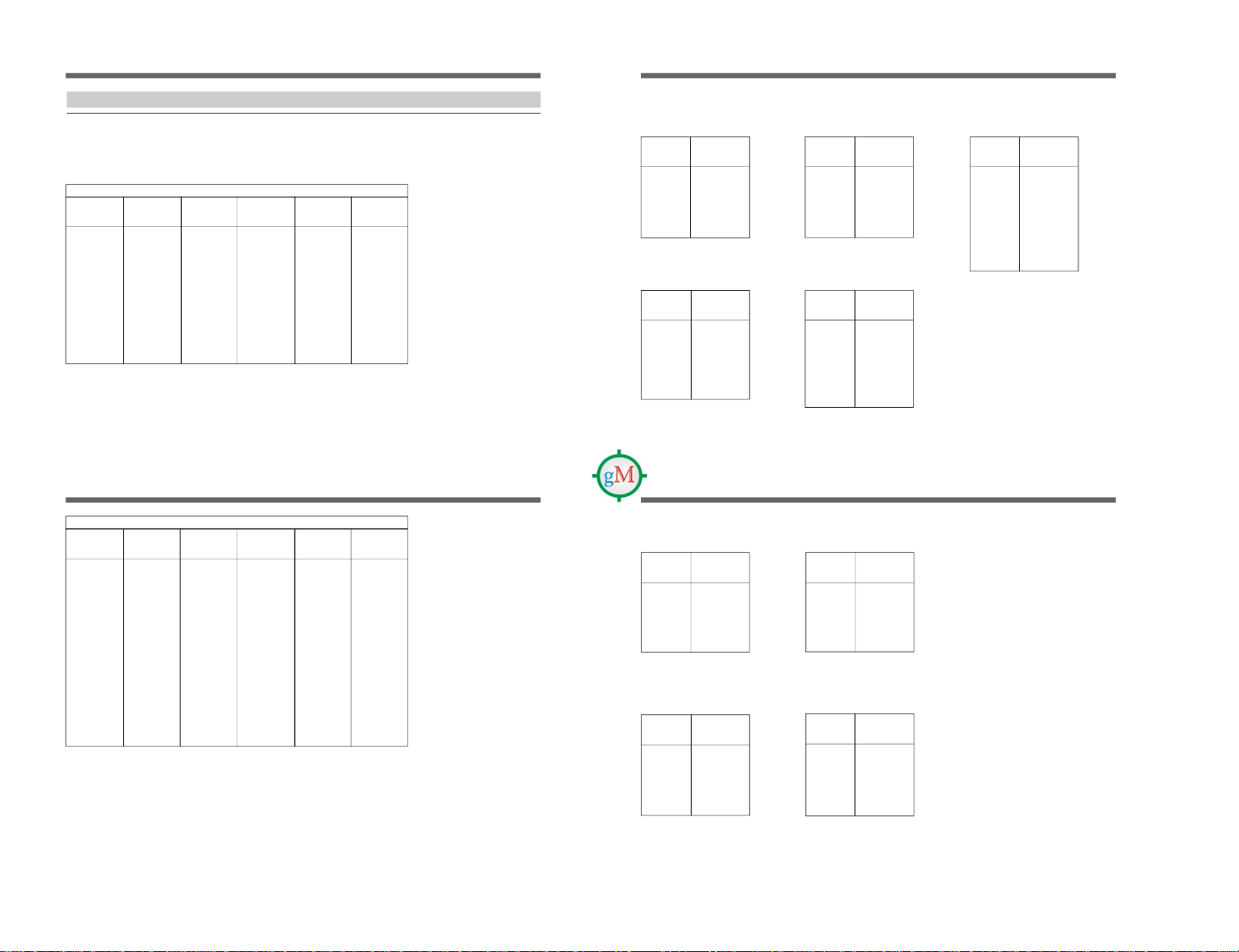
Overview of Channel Plan / Überblick über die Kanäle / Descripción general del plan de canales
Guidance on use of multi-channel system
This product is designed to give excellent interference free
operation in multi-channel systems. To maintain this, Sony
recommends that one of the original Sony groups, number
01, 02, 03, 04, 13, L1, L2, M1 or M2 is selected.
These groups will offer excellent performance, free from
mutual interference from other Sony wireless microphone
transmitters in the selected group when used under the
recommended operating conditions. The remaining groups
are included for compliance with frequency regulations in
various countries, and will not always guarantee
interference free operation.
Group 00 is used to scan for open channels, or to use only
for a one channel system.
Richtlinien für ein Mehrkanalsystem
Dieses Produkt wurde im Hinblick auf hervorragenden
interferenzfreien Betrieb in Mehrkanalsystemen entwickelt.
Deshalb empfehlen wir, eine der Sony-Kanalgruppen,
Nummer 01, 02, 03, 04, 13, L1, L2, M1 oder M2,
auszuwählen.
Bei diesen Gruppen erzielen Sie eine außerordentliche
Leistung ohne gegenseitige Interferenzen durch andere
schnurlose Mikrofonsender von Sony in der ausgewählten
Gruppe, vorausgesetzt, die empfohlenen
Betriebsbedingungen werden eingehalten. Bei den übrigen
Gruppen gelten die Frequenzbestimmungen in verschiedenen
Ländern, und ein interferenzfreier Betrieb kann nicht immer
gewährleistet werden.
Gruppe 00 dient zum Durchsuchen offener Kanäle bzw.
eignet sich für ein Einkanalsystem.
Directrices para el uso de sistemas multicanal
Este producto se ha diseñado para proporcionar una
operación excelente sin interferencias en sistemas de
múltiples canales. Para esto, Sony recomienda seleccionar
uno de los grupos originales de Sony, es decir, los número
01, 02, 03, 04, 13, L1, L2, M1 o M2.
Estos grupos ofrecen un funcionamiento excelente, sin
interferencias en ambos sentidos con otros transmisores de
micrófono inalámbrico de Sony del grupo seleccionado,
siempre que se utilicen en las condiciones de funcionamiento
recomendadas. Los demás grupos se han incluido por
motivos de compatibilidad con las normas sobre frecuencias
de varios países y no siempre garantizarán un
funcionamiento sin interferencias.
El grupo 00 sirve para buscar canales abiertos o se utiliza
solamente para sistemas de un solo canal.
L-2
Wireless Channel Lists / Übertragungskanallisten / Listas de canales inalámbricos
German-4
Deutsch-4
Alemanes 4
No. of
simultaneously
selectable channels
Anzahl der
Simultankanäle
Canales
seleccionables de
forma simultánea
*(111)
8
9
8
10
12
8
*(7)
*(8)
*(7)
*(7)
*(10)
*(10)
*(12)
*(10)
*(10)
Model
Modell
Modelo
CE62
User
group
Benutzer-
gruppe
Grupo de
usuarios
Sony
German-3
Deutsch-3
Alemanes 3
German-4
Deutsch-4
Alemanes 4
Group
indication
Gruppe-
Anzeige
Indicación
de grupo
00
01
02
03
04
13
L1
L2
M1
M2
62A
62B
62C
62D
62E
63A
63B
63C
63D
Frequency
grid
Frequenz-
raster
ID de
frecuencia
125 kHz
No. of
simultaneously
selectable channels
Anzahl der
Simultankanäle
Canales
seleccionables de
forma simultánea
Group
indication
Gruppe-
Anzeige
Indicación
de grupo
63E
62
63
Frequency
grid
Frequenz-
raster
ID de
frecuencia
25 kHz
User
group
Benutzer-
gruppe
Grupo de
usuarios
Model
Modell
Modelo
CE62
Sony = Sony original channel groups / Sony-Kanalgruppen / Grupos de
canales originales de Sony
German = German User Groups
Deutsch = Deutsche Benutzergruppen
Alemanes = Grupos de usuarios alemanes
*
-marked number means a total number of selectable channels (not
simultaneously).
Die Anzahl der insgesamt wählbaren Kanäle ist mit einem Stern (
*
)
gekennzeichnet.
Los números marcados con
*
indican un número total de canales
seleccionables (no simultáneos).
German
Deutsch
Alemanes
25 kHz
German-3
Deutsch-3
Alemanes 3
*(241)
*(320)
*(11)
L-3
No. of
simultaneously
selectable channels
Anzahl der
Simultankanäle
Canales
seleccionables de
forma simultánea
*(64)
10
*(7)
*(7)
Model
Modell
Modelo
CE69
Group
indication
Gruppe-
Anzeige
Indicación
de grupo
00
01
L
H
Frequency
grid
Frequenz-
raster
ID de
frecuencia
125 kHz
25 kHz
User
group
Benutzer-
gruppe
Grupo de
usuarios
Sony
UK
General
Use
Allgemeine
Verwendung
in Groß-
britannien
Uso
general
para el
Reino
Unido
Sony = Sony original channel groups / Sony-Kanalgruppen / Grupos de
canales originales de Sony
German = German User Groups
Deutsch = Deutsche Benutzergruppen
Alemanes = Grupos de usuarios alemanes
*
-marked number means a total number of selectable channels (not
simultaneously).
Die Anzahl der insgesamt wählbaren Kanäle ist mit einem Stern (
*
)
gekennzeichnet.
Los números marcados con
*
indican un número total de canales
seleccionables (no simultáneos).

1-6 WRR-805A (CE, AU)
L-4
Wireless Channel Lists / Übertragungskanallisten / Listas de canales inalámbricos
CE62 Model / Modell CE62 / Modelo CE62
Sony Original Channel Groups / Sony-Kanalgruppen / Grupos de canales originales de Sony
(Channel spacing=125kHz) /(Kanalabstand = 125 kHz) / (Espaciado entre canales = 125 kHz)
GP/CH indication (example) / GP/CH-Anzeige (Beispiel) / Indicación GP/CH (ejemplo) : 00.6217
Group 00: 111-channel group (single-channel operation) / Gruppe 00: 111-Kanal-Gruppe (Einkanalbetrieb) / Grupo 00: grupo de 111 canales
(operación con un solo canal)
WL Channel
WL-Kanal
Canal WL
Frequency
Frequenz (MHz)
Frecuencia
WL Channel
WL-Kanal
Canal WL
Frequency
Frequenz (MHz)
Frecuencia
WL Channel
WL-Kanal
Canal WL
Frequency
Frequenz (MHz)
Frecuencia
62-17
62-18
62-19
62-20
62-21
62-22
62-23
62-24
62-25
62-26
62-27
62-28
62-29
62-30
62-31
62-32
62-33
62-34
62-35
62-36
62-37
62-38
62-39
62-40
62-41
62-42
62-43
62-44
62-45
62-46
62-47
62-48
62-49
62-50
62-51
62-52
62-53
62-54
62-55
62-56
62-57
62-58
62-59
62-60
62-61
62-62
62-63
800.125
800.250
800.375
800.500
800.625
800.750
800.875
801.000
801.125
801.250
801.375
801.500
801.625
801.750
801.875
802.000
802.125
802.250
802.375
802.500
802.625
802.750
802.875
803.000
803.125
803.250
803.375
803.500
803.625
803.750
803.875
804.000
804.125
804.250
804.375
804.500
804.625
804.750
804.875
805.000
805.125
805.250
805.375
805.500
805.625
805.750
805.875
TV-62 Band / TV-62-Frequenzbereich / Banda 62 de TV
WL Channel = Wireless Channel/WL-Kanal = Übertragungskanal/Canal WL = canal inalámbrico
L-5
WL Channel
WL-Kanal
Canal WL
Frequency
Frequenz (MHz)
Frecuencia
WL Channel
WL-Kanal
Canal WL
Frequency
Frequenz (MHz)
Frecuencia
WL Channel
WL-Kanal
Canal WL
Frequency
Frequenz (MHz)
Frecuencia
63-00
63-01
63-02
63-03
63-04
63-05
63-06
63-07
63-08
63-09
63-10
63-11
63-12
63-13
63-14
63-15
63-16
63-17
63-18
63-19
63-20
63-21
63-22
63-23
63-24
63-25
63-26
63-27
63-28
63-29
63-30
63-31
63-32
63-33
63-34
63-35
63-36
63-37
63-38
63-39
63-40
63-41
63-42
63-43
63-44
63-45
63-46
63-47
63-48
63-49
63-50
63-51
63-52
63-53
63-54
63-55
63-56
63-57
63-58
63-59
63-60
63-61
63-62
63-63
806.000
806.125
806.250
806.375
806.500
806.625
806.750
806.875
807.000
807.125
807.250
807.375
807.500
807.625
807.750
807.875
808.000
808.125
808.250
808.375
808.500
808.625
808.750
808.875
809.000
809.125
809.250
809.375
809.500
809.625
809.750
809.875
810.000
810.125
810.250
810.375
810.500
810.625
810.750
810.875
811.000
811.125
811.250
811.375
811.500
811.625
811.750
811.875
812.000
812.125
812.250
812.375
812.500
812.625
812.750
812.875
813.000
813.125
813.250
813.375
813.500
813.625
813.750
813.875
TV-63 Band / TV-63-Frequenzbereich / Banda 63 de TV
L-6
Wireless Channel Lists / Übertragungskanallisten / Listas de canales inalámbricos
62-17 800.125
62-21 800.625
62-32 802.000
62-50 804.250
63-10 807.250
63-12 807.500
63-31 809.875
63-58 813.250
WL Channel
WL-Kanal
Canal WL
Frequency
Frequenz (MHz)
Frecuencia
WL Channel
WL-Kanal
Canal WL
Frequency
Frequenz (MHz)
Frecuencia
62-19 800.375
62-30 801.750
62-38 802.750
62-58 805.250
63-08 807.000
63-25 809.125
63-41 811.125
63-62 813.750
WL Channel
WL-Kanal
Canal WL
Frequency
Frequenz (MHz)
Frecuencia
62-18 800.250
62-23 800.875
62-46 803.750
62-56 805.000
62-59 805.375
63-14 807.750
63-22 808.750
63-29 809.625
63-38 810.750
WL Channel
WL-Kanal
Canal WL
Frequency
Frequenz (MHz)
Frecuencia
62-20 800.500
62-22 800.750
62-25 801.125
62-29 801.625
62-35 802.375
62-47 803.875
63-06 806.750
63-27 809.375
63-43 811.375
63-60 813.500
Group 01/Gruppe 01/Grupo 01
8-channel group
8-Kanal-Gruppe
Grupo de 8 canales
Group 02/Gruppe 02/Grupo 02
9-channel group
9-Kanal-Gruppe
Grupo de 9 canales
Group 04/Gruppe 04/Grupo 04
10-channel group
10-Kanal-Gruppe
Grupo de 10 canales
Group 13/Gruppe 13/Grupo 13
12-channel group
12-Kanal-Gruppe
Grupo de 12 canales
Group 03/Gruppe 03/Grupo 03
8-channel group
8-Kanal-Gruppe
Grupo de 8 canales
WL Channel
WL-Kanal
Canal WL
Frequency
Frequenz (MHz)
Frecuencia
62-17 800.125
62-22 800.750
62-32 802.000
62-34 802.250
62-50 804.250
62-58 805.250
63-15 807.875
63-26 809.250
63-40 811.000
63-46 811.750
63-49 812.125
63-53 812.625
L-7
62-22 800.750
62-24 801.000
62-28 801.500
62-38 802.750
62-41 803.125
62-49 804.125
62-56 805.000
62-61 805.625
WL Channel
WL-Kanal
Canal WL
Frequency
Frequenz (MHz)
Frecuencia
Group L1/Gruppe L1/Grupo L1
8-channel group / 8-Kanal-Gruppe/
Grupo de 8 canales
62-19 800.375
62-21 800.625
62-27 801.375
62-32 802.000
62-42 803.250
62-51 804.375
62-54 804.750
62-58 805.250
WL Channel
WL-Kanal
Canal WL
Frequency
Frequenz (MHz)
Frecuencia
Group M1/Gruppe M1/GrupoM1
8-channel group / 8-Kanal-Gruppe/
Grupo de 8 canales
63-11 807.375
63-13 807.625
63-19 808.375
63-24 809.000
63-34 810.250
63-43 811.375
63-46 811.750
63-50 812.250
WL Channel
WL-Kanal
Canal WL
Frequency
Frequenz (MHz)
Frecuencia
Group L2/Gruppe L2/Grupo L2
8-channel group / 8-Kanal-Gruppe/
Grupo de 8 canales
WL Channel
WL-Kanal
Canal WL
Frequency
Frequenz (MHz)
Frecuencia
Group M2/Gruppe M2/Grupo M2
8-channel group / 8-Kanal-Gruppe/
Grupo de 8 canales
63-14 807.750
63-16 808.000
63-20 808.500
63-30 809.750
63-33 810.125
63-41 811.125
63-48 812.000
63-53 812.625

1-7
WRR-805A (CE, AU)
L-8
Wireless Channel Lists / Übertragungskanallisten / Listas de canales inalámbricos
WL Channel
WL-Kanal
Canal WL
Frequency
Frequenz (MHz)
Frecuencia
62-C04 800.425
62-C05 801.000
62-C06 801.825
62-C07 802.925
62-C08 803.450
62-C09 804.675
62-C10 805.650
Group 62C/Gruppe 62C/Grupo 62C
7-channel group / 7-Kanal-Gruppe/
Grupo de 7 canales
WL Channel
WL-Kanal
Canal WL
Frequency
Frequenz (MHz)
Frecuencia
62-D04 800.475
62-D05 801.050
62-D06 801.875
62-D07 802.975
62-D08 803.500
62-D09 804.725
62-D10 805.700
Group 62D/Gruppe 62D/Grupo 62D
7-channel group / 7-Kanal-Gruppe /
Grupo de 7 canales
German User Group-3 / Deutsche Benutzergruppe-3 / Grupo de usuarios alemanes 3
(Channel spacing=25kHz) / (Kanalabstand= 25 kHz) / (Espaciado entre canales = 25 kHz)
GP/CH indication (example) / GP/CH-Anzeige (Beispiel) / Indicación GP/CH (ejemplo) : 62A 04
Group 62A/Gruppe 62A/Grupo 62A
7-channel group / 7-Kanal-Gruppe/
Grupo de 7 canales
Group 62B/Gruppe 62B/Grupo 62B
8-channel group / 8-Kanal-Gruppe/
Grupo de 8 canales
WL Channel
WL-Kanal
Canal WL
Frequency
Frequenz (MHz)
Frecuencia
62-A04 800.325
62-A05 800.900
62-A06 801.725
62-A07 802.825
62-A08 803.350
62-A09 804.100
62-A10 804.575
WL Channel
WL-Kanal
Canal WL
Frequency
Frequenz (MHz)
Frecuencia
62-B05 800.375
62-B06 800.950
62-B07 801.775
62-B08 802.875
62-B09 803.400
62-B10 804.150
62-B11 804.625
62-B12 805.600
WL Channel
WL-Kanal
Canal WL
Frequency
Frequenz (MHz)
Frecuencia
63-A01 806.250
63-A02 807.200
63-A03 807.900
63-A04 808.325
63-A05 808.900
63-A06 809.725
63-A07 810.825
63-A08 811.350
63-A09 812.100
63-A10 812.575
Group 63A/Gruppe 63A/Grupo 63A
10-channel group / 10-Kanal-Gruppe /
Grupo de 10 canales
L-9
WL Channel
WL-Kanal
Canal WL
Frequency
Frequenz (MHz)
Frecuencia
63-C01 806.350
63-C02 806.750
63-C03 807.300
63-C04 808.425
63-C05 809.000
63-C06 809.825
63-C07 810.925
63-C08 811.450
63-C09 812.675
63-C10 813.650
Group 63C/Gruppe 63C/Grupo
63C
10-channel group / 10-Kanal-
Gruppe / Grupo de 10 canales
WL Channel
WL-Kanal
Canal WL
Frequency
Frequenz (MHz)
Frecuencia
63-D01 806.400
63-D02 806.800
63-D03 807.350
63-D04 808.475
63-D05 809.050
63-D06 809.875
63-D07 810.975
63-D08 811.500
63-D09 812.725
63-D10 813.700
Group 63D/Gruppe 63D/Grupo
63D
10-channel group / 10-Kanal-
Gruppe / Grupo de 10 canales
German User Group-4
Deutsche Benutzergruppe-4
Grupo de usuarios alemanes 4
(Channel spacing=25kHz) / (Kanalabstand = 25 kHz) /
(Espaciado entre canales = 25 kHz)
GP/CH indication (example) / GP/CH-Anzeige (Beispiel) /
Indicación GP/CH (ejemplo) : 62E 02
WL Channel
WL-Kanal
Canal WL
Frequency
Frequenz (MHz)
Frecuencia
Group 62E/Gruppe 62E/Grupo
62E
10-channel group
10-Kanal-Gruppe
Grupo de 10 canales
62-E02 800.525
62-E03 801.100
62-E04 801.425
62-E05 801.975
62-E06 802.575
62-E07 803.050
62-E08 803.700
62-E09 804.800
62-E10 805.050
62-E11 805.775
WL Channel
WL-Kanal
Canal WL
Frequency
Frequenz (MHz)
Frecuencia
Group 63E/Gruppe 63E/Grupo
63E
11-channel group
11-Kanal-Gruppe
Grupo de 11 canales
63-E01 806.850
63-E02 808.525
63-E03 809.100
63-E04 809.425
63-E05 809.975
63-E06 810.575
63-E07 811.050
63-E08 811.700
63-E09 812.800
63-E10 813.050
63-E11 813.775
WL Channel
WL-Kanal
Canal WL
Frequency
Frequenz (MHz)
Frecuencia
63-B01 806.300
63-B02 806.700
63-B03 807.250
63-B04 807.950
63-B05 808.375
63-B06 808.950
63-B07 809.775
63-B08 810.875
63-B09 811.400
63-B10 812.150
63-B11 812.625
63-B12 813.600
Group 63B/Gruppe 63B/Grupo
63B
12-channel group / 12-Kanal-
Gruppe / Grupo de 12 canales
L-10
Wireless Channel Lists / Übertragungskanallisten / Listas de canales inalámbricos
German User Groups / Deutsche Benutzergruppen / Grupos de usuarios alemanes
(Channel spacing 25kHz) / (Kanalabstand = 25 kHz) / (Espaciado entre canales = 25 kHz)
GP/CH indication (example) / GP/CH-Anzeige (Beispiel) / Indicación GP/CH (ejemplo) : 62 080
Group 62: 241-channel group (single-channel operation) / Gruppe 62: 241-Kanal-Gruppe (Einkanalbetrieb) / Grupo 62: grupo de 241 canales
(operación con un solo canal)
Frequency range: 800.000 to 806.000 MHz / Frequenzbereich: 800,000 bis 806,000 MHz / Rango de frecuencias: 800,000 a 806,000 MHz
62-161 802.025
62-162 802.050
62-163 802.075
62-164 802.100
62-165 802.125
62-166 802.150
62-167 802.175
62-168 802.200
62-169 802.225
62-170 802.250
62-171 802.275
62-172 802.300
62-173 802.325
62-174 802.350
62-175 802.375
62-176 802.400
62-177 802.425
62-178 802.450
62-179 802.475
62-180 802.500
62-181 802.525
62-182 802.550
62-183 802.575
62-184 802.600
62-185 802.625
62-186 802.650
62-187 802.675
WL Channel
WL-Kanal
Canal WL
Frequency
Frequenz (MHz)
Frecuencia
WL Channel
WL-Kanal
Canal WL
Frequency
Frequenz (MHz)
Frecuencia
62-080 800.000
62-081 800.025
62-082 800.050
62-083 800.075
62-084 800.100
62-085 800.125
62-086 800.150
62-087 800.175
62-088 800.200
62-089 800.225
62-090 800.250
62-091 800.275
62-092 800.300
62-093 800.325
62-094 800.350
62-095 800.375
62-096 800.400
62-097 800.425
62-098 800.450
62-099 800.475
62-100 800.500
62-101 800.525
62-102 800.550
62-103 800.575
62-104 800.600
62-105 800.625
62-106 800.650
62-107 800.675
62-108 800.700
62-109 800.725
62-110 800.750
62-111 800.775
62-112 800.800
62-113 800.825
62-114 800.850
62-115 800.875
62-116 800.900
62-117 800.925
62-118 800.950
62-119 800.975
62-120 801.000
62-121 801.025
62-122 801.050
62-123 801.075
62-124 801.100
62-125 801.125
62-126 801.150
62-127 801.175
62-128 801.200
62-129 801.225
62-130 801.250
62-131 801.275
62-132 801.300
62-133 801.325
WL Channel
WL-Kanal
Canal WL
Frequency
Frequenz (MHz)
Frecuencia
WL Channel
WL-Kanal
Canal WL
Frequency
Frequenz (MHz)
Frecuencia
62-134 801.350
62-135 801.375
62-136 801.400
62-137 801.425
62-138 801.450
62-139 801.475
62-140 801.500
62-141 801.525
62-142 801.550
62-143 801.575
62-144 801.600
62-145 801.625
62-146 801.650
62-147 801.675
62-148 801.700
62-149 801.725
62-150 801.750
62-151 801.775
62-152 801.800
62-153 801.825
62-154 801.850
62-155 801.875
62-156 801.900
62-157 801.925
62-158 801.950
62-159 801.975
62-160 802.000
L-11
62-222 803.550
62-223 803.575
62-224 803.600
62-225 803.625
62-226 803.650
62-227 803.675
62-228 803.700
62-229 803.725
62-230 803.750
62-231 803.775
62-232 803.800
62-233 803.825
62-234 803.850
62-235 803.875
62-236 803.900
62-237 803.925
62-238 803.950
62-239 803.975
62-240 804.000
62-241 804.025
62-242 804.050
62-243 804.075
62-244 804.100
62-245 804.125
62-246 804.150
62-247 804.175
62-248 804.200
62-249 804.225
62-250 804.250
62-251 804.275
62-252 804.300
62-253 804.325
62-254 804.350
62-255 804.375
62-188 802.700
62-189 802.725
62-190 802.750
62-191 802.775
62-192 802.800
62-193 802.825
62-194 802.850
62-195 802.875
62-196 802.900
62-197 802.925
62-198 802.950
62-199 802.975
62-200 803.000
62-201 803.025
62-202 803.050
62-203 803.075
62-204 803.100
62-205 803.125
62-206 803.150
62-207 803.175
62-208 803.200
62-209 803.225
62-210 803.250
62-211 803.275
62-212 803.300
62-213 803.325
62-214 803.350
62-215 803.375
62-216 803.400
62-217 803.425
62-218 803.450
62-219 803.475
62-220 803.500
62-221 803.525
WL Channel
WL-Kanal
Canal WL
Frequency
Frequenz (MHz)
Frecuencia
WL Channel
WL-Kanal
Canal WL
Frequency
Frequenz (MHz)
Frecuencia
WL Channel
WL-Kanal
Canal WL
Frequency
Frequenz (MHz)
Frecuencia
WL Channel
WL-Kanal
Canal WL
Frequency
Frequenz (MHz)
Frecuencia
62-256 804.400
62-257 804.425
62-258 804.450
62-259 804.475
62-260 804.500
62-261 804.525
62-262 804.550
62-263 804.575
62-264 804.600
62-265 804.625
62-266 804.650
62-267 804.675
62-268 804.700
62-269 804.725
62-270 804.750
62-271 804.775
62-272 804.800
62-273 804.825
62-274 804.850
62-275 804.875
62-276 804.900
62-277 804.925
62-278 804.950
62-279 804.975
62-280 805.000
62-281 805.025
62-282 805.050
62-283 805.075
62-284 805.100
62-285 805.125
62-286 805.150
62-287 805.175
62-288 805.200
62-289 805.225
62-290 805.250
62-291 805.275
62-292 805.300
62-293 805.325
62-294 805.350
62-295 805.375
62-296 805.400
62-297 805.425
62-298 805.450
62-299 805.475
62-300 805.500
62-301 805.525
62-302 805.550
62-303 805.575
62-304 805.600
62-305 805.625
62-306 805.650
62-307 805.675
62-308 805.700
62-309 805.725
62-310 805.750
62-311 805.775
62-312 805.800
62-313 805.825
62-314 805.850
62-315 805.875
62-316 805.900
62-317 805.925
62-318 805.950
62-319 805.975
62-320 806.000

1-8 WRR-805A (CE, AU)
L-12
Wireless Channel Lists / Übertragungskanallisten / Listas de canales inalámbricos
GP/CH indication (example) / GP/CH-Anzeige (Beispiel) / Indicación GP/CH (ejemplo): 63 001
Group 63: 320-channel group (single-channel operation) / Gruppe 63: 320-Kanal-Gruppe (Einkanalbetrieb) / Grupo 63: grupo de 320 canales
(operación con un solo canal)
Frequency range: 806.025 to 814.000 MHz / Frequenzbereich: 806,025 bis 814,000 MHz / Rango de frecuencias: 806,025 a 814,000 MHz
WL Channel
WL-Kanal
Canal WL
Frequency
Frequenz (MHz)
Frecuencia
WL Channel
WL-Kanal
Canal WL
WL Channel
WL-Kanal
Canal WL
Frequency
Frequenz (MHz)
Frecuencia
WL Channel
WL-Kanal
Canal WL
Frequency
Frequenz (MHz)
Frecuencia
Frequency
Frequenz (MHz)
Frecuencia
63-059 807.475
63-060 807.500
63-061 807.525
63-062 807.550
63-063 807.575
63-064 807.600
63-065 807.625
63-066 807.650
63-067 807.675
63-068 807.700
63-069 807.725
63-070 807.750
63-071 807.775
63-072 807.800
63-073 807.825
63-074 807.850
63-075 807.875
63-076 807.900
63-077 807.925
63-078 807.950
63-079 807.975
63-080 808.000
63-081 808.025
63-082 808.050
63-083 808.075
63-084 808.100
63-085 808.125
63-086 808.150
63-087 808.175
63-088 808.200
63-089 808.225
63-090 808.250
63-091 808.275
63-092 808.300
63-093 808.325
63-094 808.350
63-095 808.375
63-096 808.400
63-097 808.425
63-098 808.450
63-099 808.475
63-100 808.500
63-101 808.525
63-102 808.550
63-103 808.575
63-104 808.600
63-105 808.625
63-106 808.650
63-107 808.675
63-108 808.700
63-109 808.725
63-110 808.750
63-111 808.775
63-112 808.800
63-113 808.825
63-114 808.850
63-115 808.875
63-116 808.900
63-001 806.025
63-002 806.050
63-003 806.075
63-004 806.100
63-005 806.125
63-006 806.150
63-007 806.175
63-008 806.200
63-009 806.225
63-010 806.250
63-011 806.275
63-012 806.300
63-013 806.325
63-014 806.350
63-015 806.375
63-016 806.400
63-017 806.425
63-018 806.450
63-019 806.475
63-020 806.500
63-021 806.525
63-022 806.550
63-023 806.575
63-024 806.600
63-025 806.625
63-026 806.650
63-027 806.675
63-028 806.700
63-029 806.725
63-030 806.750
63-031 806.775
63-032 806.800
63-033 806.825
63-034 806.850
63-035 806.875
63-036 806.900
63-037 806.925
63-038 806.950
63-039 806.975
63-040 807.000
63-041 807.025
63-042 807.050
63-043 807.075
63-044 807.100
63-045 807.125
63-046 807.150
63-047 807.175
63-048 807.200
63-049 807.225
63-050 807.250
63-051 807.275
63-052 807.300
63-053 807.325
63-054 807.350
63-055 807.375
63-056 807.400
63-057 807.425
63-058 807.450
L-13
63-117 808.925
63-118 808.950
63-119 808.975
63-120 809.000
63-121 809.025
63-122 809.050
63-123 809.075
63-124 809.100
63-125 809.125
63-126 809.150
63-127 809.175
63-128 809.200
63-129 809.225
63-130 809.250
63-131 809.275
63-132 809.300
63-133 809.325
63-134 809.350
63-135 809.375
63-136 809.400
63-137 809.425
63-138 809.450
63-139 809.475
63-140 809.500
63-141 809.525
63-142 809.550
63-143 809.575
63-144 809.600
63-145 809.625
63-146 809.650
63-147 809.675
63-148 809.700
63-149 809.725
63-150 809.750
63-151 809.775
63-152 809.800
63-153 809.825
63-154 809.850
63-155 809.875
63-156 809.900
63-157 809.925
63-158 809.950
63-159 809.975
63-160 810.000
63-161 810.025
63-162 810.050
63-163 810.075
63-164 810.100
63-165 810.125
63-166 810.150
63-167 810.175
63-168 810.200
63-169 810.225
63-170 810.250
63-171 810.275
63-172 810.300
63-173 810.325
63-174 810.350
63-175 810.375
63-176 810.400
63-177 810.425
63-178 810.450
63-179 810.475
63-180 810.500
63-181 810.525
63-182 810.550
63-183 810.575
63-184 810.600
63-219 811.475
63-220 811.500
63-221 811.525
63-222 811.550
63-223 811.575
63-224 811.600
63-225 811.625
63-226 811.650
63-227 811.675
63-228 811.700
63-229 811.725
63-230 811.750
63-231 811.775
63-232 811.800
63-233 811.825
63-234 811.850
63-235 811.875
63-236 811.900
63-237 811.925
63-238 811.950
63-239 811.975
63-240 812.000
63-241 812.025
63-242 812.050
63-243 812.075
63-244 812.100
63-245 812.125
63-246 812.150
63-247 812.175
63-248 812.200
63-249 812.225
63-250 812.250
63-251 812.275
63-252 812.300
63-185 810.625
63-186 810.650
63-187 810.675
63-188 810.700
63-189 810.725
63-190 810.750
63-191 810.775
63-192 810.800
63-193 810.825
63-194 810.850
63-195 810.875
63-196 810.900
63-197 810.925
63-198 810.950
63-199 810.975
63-200 811.000
63-201 811.025
63-202 811.050
63-203 811.075
63-204 811.100
63-205 811.125
63-206 811.150
63-207 811.175
63-208 811.200
63-209 811.225
63-210 811.250
63-211 811.275
63-212 811.300
63-213 811.325
63-214 811.350
63-215 811.375
63-216 811.400
63-217 811.425
63-218 811.450
WL Channel
WL-Kanal
Canal WL
Frequency
Frequenz (MHz)
Frecuencia
WL Channel
WL-Kanal
Canal WL
Frequency
Frequenz (MHz)
Frecuencia
WL Channel
WL-Kanal
Canal WL
Frequency
Frequenz (MHz)
Frecuencia
WL Channel
WL-Kanal
Canal WL
Frequency
Frequenz (MHz)
Frecuencia
L-14
Wireless Channel Lists / Übertragungskanallisten / Listas de canales inalámbricos
63-253 812.325
63-254 812.350
63-255 812.375
63-256 812.400
63-257 812.425
63-258 812.450
63-259 812.475
63-260 812.500
63-261 812.525
63-262 812.550
63-263 812.575
63-264 812.600
63-265 812.625
63-266 812.650
63-267 812.675
63-268 812.700
63-269 812.725
63-270 812.750
63-271 812.775
63-272 812.800
63-273 812.825
63-274 812.850
63-275 812.875
63-276 812.900
63-277 812.925
63-278 812.950
63-279 812.975
63-280 813.000
63-281 813.025
63-282 813.050
63-283 813.075
63-284 813.100
63-285 813.125
63-286 813.150
63-287 813.175
63-288 813.200
63-289 813.225
63-290 813.250
63-291 813.275
63-292 813.300
63-293 813.325
63-294 813.350
63-295 813.375
63-296 813.400
63-297 813.425
63-298 813.450
WL Channel
WL-Kanal
Canal WL
Frequency
Frequenz (MHz)
Frecuencia
WL Channel
WL-Kanal
Canal WL
Frequency
Frequenz (MHz)
Frecuencia
WL Channel
WL-Kanal
Canal WL
Frequency
Frequenz (MHz)
Frecuencia
63-299 813.475
63-300 813.500
63-301 813.525
63-302 813.550
63-303 813.575
63-304 813.600
63-305 813.625
63-306 813.650
63-307 813.675
63-308 813.700
63-309 813.725
63-310 813.750
63-311 813.775
63-312 813.800
63-313 813.825
63-314 813.850
63-315 813.875
63-316 813.900
63-317 813.925
63-318 813.950
63-319 813.975
63-320 814.000
L-15
Sony Original Channel Groups / Sony-Kanalgruppen / Grupos de canales originales de Sony
(Channel spacing 125kHz) / (Kanalabstand = 125 kHz) / (Espaciado entre canales = 125 kHz)
GP/CH indication (example) / GP/CH-Anzeige (Beispiel) / Indicación GP/CH (ejemplo) : 00.6901
CE69 Model / Modell CE69 / Modelo CE69
Group 00: 64-channel group (single-channel operation) / Gruppe 00: 64-Kanal-Gruppe
(Einkanalbetrieb) / Grupo 00: grupo de 64 canales (operación con un solo canal)
WL Channel
WL-Kanal
Canal WL
Frequency
Frequenz (MHz)
Frecuencia
WL Channel
WL-Kanal
Canal WL
Frequency
Frequenz (MHz)
Frecuencia
WL Channel
WL-Kanal
Canal WL
Frequency
Frequenz (MHz)
Frecuencia
TV-69 Band / TV-69-Frequenzbereich / Banda 69 de TV
WL Channel
WL-Kanal
Canal WL
Frequency
Frequenz (MHz)
Frecuencia
69-01 854.125
69-02 854.250
69-03 854.375
69-04 854.500
69-05 854.625
69-06 854.750
69-07 854.875
69-08 855.000
69-09 855.125
69-10 855.250
69-11 855.375
69-12 855.500
69-13 855.625
69-14 855.750
69-15 855.875
69-16 856.000
69-17 856.125
69-18 856.250
69-19 856.375
69-20 856.500
69-21 856.625
69-22 856.750
69-23 856.875
69-24 857.000
69-25 857.125
69-26 857.250
69-27 857.375
69-28 857.500
69-29 857.625
69-30 857.750
69-31 857.875
69-32 858.000
69-33 858.125
69-34 858.250
69-35 858.375
69-36 858.500
69-37 858.625
69-38 858.750
69-39 858.875
69-40 859.000
69-41 859.125
69-42 859.250
69-43 859.375
69-44 859.500
69-45 859.625
69-46 859.750
69-47 859.875
69-48 860.000
69-49 860.125
69-50 860.250
69-51 860.375
69-52 860.500
69-53 860.625
69-54 860.750
69-55 860.875
69-56 861.000
69-57 861.125
69-58 861.250
69-59 861.375
69-60 861.500
69-61 861.625
69-62 861.750
69-63 861.875
69-64 862.000
WL Channel = Wireless Channel / WL-Kanal = Übertragungskanal / Canal WL = canal inalámbrico

1-9
WRR-805A (CE, AU)
L-16
Wireless Channel Lists / Übertragungskanallisten / Listas de canales inalámbricos
UK General Use Groups
Gruppen für allgem. Verwendung in Großbritannien
Grupos de uso general para el Reino Unido
(Channel spacing 25kHz) / (Kanalabstand = 25 kHz) /
(Espaciado entre canales = 25 kHz)GP/CH indication (example) /
GP/CH-Anzeige (Beispiel) / Indicación GP/CH (ejemplo) : L UG01
WL Channel
WL-Kanal
Canal WL
Frequency
Frequenz (MHz)
Frecuencia
Group H/Gruppe H/Grupo H
7-channel group
7-Kanal-Gruppe
Grupo de 7 canales
UG-08 858.200
UG-09 858.650
UG-10 860.400
UG-11 860.900
UG-12 861.200
UG-13 861.550
UG-14 861.750
WL Channel
WL-Kanal
Canal WL
Frequency
Frequenz (MHz)
Frecuencia
Group L/Gruppe L/Grupo L
7-channel group
7-Kanal-Gruppe
Grupo de 7 canales
UG-01 854.900
UG-02 855.275
UG-03 855.900
UG-04 856.175
UG-05 856.575
UG-06 857.625
UG-07 857.950
WL Channel
WL-Kanal
Canal WL
Frequency
Frequenz (MHz)
Frecuencia
Group 01/Gruppe 01/Grupo 01
10-channel group
10-Kanal-Gruppe
Grupo de 10 canales
69-01 854.125
69-03 854.375
69-07 854.875
69-18 856.250
69-27 857.375
69-34 858.250
69-46 859.750
69-56 861.000
69-59 861.375
69-64 862.000

1-10 WRR-805A (CE, AU)
3-866-674-31 (1)
WRR-805A
UHF Synthesized
Portable Tuner
Operating Instructions
1999 by Sony Corporation
[AU66]
2
Table of Contents
Overview............................................................................. 3
Features .......................................................................... 3
System Configuration .................................................... 4
Wireless Channels Selectable ........................................... 4
Precautions......................................................................... 8
Parts Identification ............................................................ 8
Power Supply ................................................................... 11
Settings.............................................................................. 12
Wireless Channel Selection ......................................... 12
Resetting the Accumulated Time Indication ............... 14
Connections ...................................................................... 15
Microphone System Operation ...................................... 15
Muting Functions ......................................................... 15
Error Messages ................................................................ 16
Use of the Soft Case ......................................................... 17
Specifications.................................................................... 18
3
Overview
The WRR-805A is a highly reliable portable tuner for the
800 MHz band Sony UHF wireless microphone system to be
used for broadcast or movie production purposes.
This tuner is suitable for Electronic News Gathering (ENG)
and Electronic Field Production (EFP).
Features
Phase Locked Loop (PLL) synthesized system
The WRR-805A has a refined phase locked loop (PLL)
synthesizer circuit.
Preprogrammed wireless channel plans for simultaneous
multi channel operation
The WRR-805A has many preprogrammed channel groups,
meaning combination of wireless channels to permit
simultaneous operation of multiple channels without
intermodulation.
Any available group and channel can be selected with a
simple button operation.
Compact and lightweight
Mounting technology and the versatile soft case enable this
compact and lightweight tuner, which lets you move
anywhere for Electronic News Gathering (ENG) and
Electronic Field Production (EFP).
Remote battery alarm from transmitter
This tuner has capability of receiving “Battery status
information” from the transmitter WRT-805A/822A to
make advance warning of battery depletion.
The information is sent in approx. one hour advance to
battery exhaust so that you can safely replace the batteries of
the transmitter.
Operation powered by easily available batteries
The built-in high efficiency DC-DC converter allows stable
operation, for about 6 hours continuously, with two LR6
(size AA) alkaline batteries.
LCD for coordinated operation control
The built-in CPU controls operation of the unit, including
the PLL circuit function. The LCD shows the current
channel number/frequency, the residual battery power, AF
output level and RF input level.
An accumulated operation time indication is also provided for
simple control of the time of battery use (in one-minute
increments).
Saved channel setting
The unit stores the channel setting when it is turned off. The
saved settings are retained even if the batteries are removed.
Therefore, when using the unit next time, you need not
make the same settings again.
1-2. WRR-805A (AU)

1-11
WRR-805A (CE, AU)
4
dnabycneuqerFdnabycneuqerFdnabycneuqerFdnabycneuqerFdnabycneuqerFemanledoMemanledoMemanledoMemanledoMemanledoM
VT
lennahc )zHM(ycneuqerF rorettimsnarTenohporcim renuT
66005.897-052.297 )66(A508-TRW
)66(A018-TRW
)66(A028-TRW
)66(A508-RRW
)66(A018-RRW
)66(A048-RRW
)66(A068-RRW
76005.508-052.997
Overview
a)
Wireless Channels Selectable
Note
This product is designed to give excellent interference free
operation in multi-channel systems. To maintain this, Sony
recommends that one of the original Sony groups, number
11, 12, 13, A1, A2, A3, L1, L2, M1, M2, H1 or H2 is
selected.
These groups will offer excellent performance, free from
mutual interference from other Sony wireless microphone
transmitters in the selected group when used under the
recommended operating conditions.
Group 00 is used to scan for open channels, or to use only
for a one channel system.
Each “wireless channel” is represented by a 2-digit TV
channel number followed by another 2-digit number, for
example: 66-01.
Wide dynamic range
The compander (compressor expander) system enables
stable reception over a wide dynamic range.
Output monitoring
The audio output can be monitored through headphones
(either of stereo or monaural). The monitoring level is
adjustable.
Muting switch for noise elimination
System Configuration
The WRR-805A can be used with the WRT-805A/820A/
822A/860A UHF synthesized transmitter or the WRT-810A/
830A/867A UHF synthesized wireless microphone.
Sony 800 MHz band system models
a) For this models, the AN-820A UHF antenna and the WD-820A UHF
antenna divider are required.
6
lennahClennahClennahClennahClennahC)zHM(ycneuqerF)zHM(ycneuqerF)zHM(ycneuqerF)zHM(ycneuqerF)zHM(ycneuqerF
60-66578.297
51-66000.497
12-66057.497
23-66521.697
64-66578.797
05-66573.897
Wireless Channels Selectable
lennahClennahClennahClennahClennahC)zHM(ycneuqerF)zHM(ycneuqerF)zHM(ycneuqerF)zHM(ycneuqerF)zHM(ycneuqerF
20-66573.297
40-66526.297
21-66526.397
42-66521.597
20-76573.997
92-76057.208
53-76005.308
44-76526.408
lennahClennahClennahClennahClennahC)zHM(ycneuqerF)zHM(ycneuqerF)zHM(ycneuqerF)zHM(ycneuqerF)zHM(ycneuqerF
10-76052.997
30-76005.997
11-76005.008
61-76521.108
32-76000.208
72-76005.208
14-76052.408
44-76526.408
05-76573.508
lennahClennahClennahClennahClennahC)zHM(ycneuqerF)zHM(ycneuqerF)zHM(ycneuqerF)zHM(ycneuqerF)zHM(ycneuqerF
20-66573.297
70-66000.397
71-66052.497
91-66005.497
53-66005.697
34-66005.797
80-76521.008
91-76005.108
33-76052.308
93-76000.408
24-76573.408
64-76578.408
Group 11: 11-channel group
Use when both TV channels 66 and 67
are available.
Group 12: 9-channel group
Use when TV channel 66 is on the air.
Group 13: 9-channel group
Use when TV channel 67 is on the air. Group A2: 6-channel group
Use when TV channel 66 is on the air.
Group A3: 6-channel group
Use when TV channel 67 is on the air.
lennahClennahClennahClennahClennahC)zHM(ycneuqerF)zHM(ycneuqerF)zHM(ycneuqerF)zHM(ycneuqerF)zHM(ycneuqerF
10-66052.297
30-66005.297
11-66005.397
61-66521.497
32-66000.597
72-66005.597
14-66052.797
44-66526.797
05-66573.897
lennahClennahClennahClennahClennahC)zHM(ycneuqerF)zHM(ycneuqerF)zHM(ycneuqerF)zHM(ycneuqerF)zHM(ycneuqerF
60-76578.997
51-76000.108
12-76057.108
23-76521.308
64-76578.408
05-76573.508
Group A1: 8-channel group
Use when both TV channels 66 and 67
are available.
5
Group 00: All channel access
Use to scan for open channels.
Use only for a one channel system.
lennahClennahClennahClennahClennahC)zHM(ycneuqerF)zHM(ycneuqerF)zHM(ycneuqerF)zHM(ycneuqerF)zHM(ycneuqerFlennahClennahClennahClennahClennahC)zHM(ycneuqerF)zHM(ycneuqerF)zHM(ycneuqerF)zHM(ycneuqerF)zHM(ycneuqerFlennahClennahClennahClennahClennahC)zHM(ycneuqerF)zHM(ycneuqerF)zHM(ycneuqerF)zHM(ycneuqerF)zHM(ycneuqerFlennahClennahClennahClennahClennahC)zHM(ycneuqerF)zHM(ycneuqerF)zHM(ycneuqerF)zHM(ycneuqerF)zHM(ycneuqerF
10-66052.29772-66005.59710-76052.99772-76005.208
20-66573.29782-66526.59720-76573.99782-76526.208
30-66005.29792-66057.59730-76005.99792-76057.208
40-66526.29703-66578.59740-76526.99703-76578.208
50-66057.29713-66000.69750-76057.99713-76000.308
60-66578.29723-66521.69760-76578.99723-76521.308
70-66000.39733-66052.69770-76000.00833-76052.308
80-66521.39743-66573.69780-76521.00843-76573.308
90-66052.39753-66005.69790-76052.00853-76005.308
01-66573.39763-66526.69701-76573.00863-76526.308
11-66005.39773-66057.69711-76005.00873-76057.308
21-66526.39783-66578.69721-76526.00883-76578.308
31-66057.39793-66000.79731-76057.00893-76000.408
41-66578.39704-66521.79741-76578.00804-76521.408
51-66000.49714-66052.79751-76000.10814-76052.408
61-66521.49724-66573.79761-76521.10824-76573.408
71-66052.49734-66005.79771-76052.10834-76005.408
81-66573.49744-66526.79781-76573.10844-76526.408
91-66005.49754-66057.79791-76005.10854-76057.408
02-66526.49764-66578.79702-76526.10864-76578.408
12-66057.49774-66000.89712-76057.10874-76000.508
22-66578.49784-66521.89722-76578.10884-76521.508
32-66000.59794-66052.89732-76000.20894-76052.508
42-66521.59705-66573.89742-76521.20805-76573.508
52-66052.59715-66005.89752-76052.20815-76005.508
62-66573.59762-76573.208
7
Channel Frequency (MHz)
66-31 796.000
66-33 796.250
66-39 797.000
66-44 797.625
66-48 798.125
66-51 798.500
Channel Frequency (MHz)
66-32 796.125
66-34 796.375
66-40 797.125
66-45 797.750
66-49 798.250
Channel Frequency (MHz)
Group L1: 6-channel group
Use when TV channel 67 is on the air. Group M1: 6-channel group
Use when TV channel 67 is on the air. Group H1: 8-channel group
Use when TV channel 66 is on the air.
Group L2: 6-channel group
Use when TV channel 67 is on the air. Group H2: 8-channel group
Use when TV channel 66 is on the air.
Group M2: 5-channel group
Use when TV channel 67 is on the air.
Channel Frequency (MHz)
66-01 792.250
66-03 792.500
66-09 793.250
66-14 793.875
66-18 794.375
66-21 794.750
Channel Frequency (MHz)
67-06 799.875
67-08 800.125
67-12 800.625
67-22 801.875
67-25 802.250
67-33 803.250
67-40 804.125
67-45 804.750
Channel Frequency (MHz)
67-03 799.500
67-05 799.750
67-11 800.500
67-16 801.125
67-26 802.375
67-35 803.500
67-38 803.875
67-42 804.375
66-02 792.375
66-04 792.625
66-10 793.375
66-15 794.000
66-19 794.500
66-22 794.875
http://getMANUAL.com

1-12 WRR-805A (CE, AU)
8
ON
OFF
MUTING
RF AF
RF TX BATT
GP CH
BATT
MODE
POWER
SET
ON
OFF
MONITOR
Wire antenna
0+/– buttons
7RF indicator
8TX BATT indicator
9MUTING switch
!¡ MONITOR control
1MONITOR
connector
2OUTPUT (BAL)
connector
3Display section
4SET button
5MODE button
6POWER switch
Battery holder
Precautions
•
The unit is designed for use in ambient temperature range
of 0°C to 50°C (32°F to 122°F).
•
Do not place the unit on or near heat sources, such as
lighting equipment, power amplifiers, or in a place subject
to direct sunlight or excessive moisture. In such places,
the external finish or internal parts of the unit may be
damaged.
•
If the unit is used in a very humid or dusty place or in a
place subject to an active gas, clean its surface as well as
the connectors with a dry, soft cloth soon after use.
Lengthy use of the unit in such places or not cleaning it
after its use in such places may shorten its life.
•
When cleaning the unit, never use organic solvents such
as thinners or benzine, which will damage the finish of the
unit.
•
The unit has been factory adjusted precisely. Do not
tamper with its internal parts or attempt to repair it.
Parts Identification
9
BBATT (battery) indication
Displays the status of the batteries of this unit.
See “Battery indication” on page 11.
CRF (radio frequency) indications
The dot indications show the RF input level. Depending on
the RF input level, the number of dots changes as below.
Four dots on: more than 45 dBµ
Three dots on: between 35 dBµand 45 dBµ
Two dots on: between 25 dBµand 35 dBµ
One dot on: between 15 dBµand 25 dBµ
No dot: less than 15 dBµ
DGP/CH (group/channel) indication
Shows the reception channel group and respective channel
number.
Each time you press the MODE button the group/channel
indication changes to the frequency and accumulated time
indications as shown below.
AB
CD
1MONITOR connector
To monitor the audio output signal, connect the headphones
equipped with 3.5 mm dia. stereo mini jack. You can use
either of stereo or monaural headphones. The monitoring
level can be adjusted with the MONITOR control.
2OUTPUT (BAL) connector
Supplies audio signals. You can connect this connector to
the microphone input connector of a Camcorder, mixer, or
tape recorder by using the supplied cable.
3Display section
Shows the status of the tuner and the groups and channels
assigned to the unit.
AAF (audio frequency) indication
Lights when the output audio signal is over the reference
level.
Group/channel
indication
Accumulated time indication
Frequency indication
10
Parts Identification
In Accumulated time indication, it displays the accumulated
time of battery use (in one-minute increments).
See “Settings” on page 12.
4SET button
Press to change and set the contents of the item on the
display.
See “Settings” on page 12.
5MODE button
Press to select the item to be set on the display.
See “Settings” on page 12.
6POWER switch
Turns the power of the tuner ON or OFF.
7RF (radio frequency) indicator
Indicates the strength of the RF input signal.
On in green: more than 25 dBµ
On in red: between 15 dBµand 25 dBµ
Off: less than 15 dBµ(less than muting
level)
8TX BATT (transmitter battery) indicator
Indicates the battery condition of the wireless microphone
transmitter. The indicator starts flashing about one hour
before the transmitter batteries go flat.
9MUTING switch
Set to ON to eliminate the noise and signal interference
when the tuner is in signal reception standby mode.
See “Muting Functions” on page 15.
0+ (+ selection) / – (– selection/reset) buttons
In setting mode, select the receiving group, channel and
frequency using either of these buttons, or reset the time-of-
use indication to “00:00” with the – button.
See “Settings” on page 12.
!¡ MONITOR control
Turn to adjust the monitoring level through headphones.
11
Battery indication
When you turn the power on, the battery status of this unit
appears in the BATT indication on the display section.
Note
The indication may be incorrect if the batteries are not new
when installed. If you plan to use the tuner for a long
period, it is best to replace the batteries with new ones.
Notes on batteries
•
Use new alkaline batteries.
•
Do not pair different types of batteries.
•
Always replace the two batteries together.
•
The batteries are not rechargeable.
•
Be careful to install the batteries with the correct polarity.
•
When not using the tuner for a long period, remove the
batteries to avoid leakage. If the batteries do leak, clean all
leakage from the battery holder case and the unit. Leakage
left in the holder case and the unit may cause poor battery
contact. If there seems to be poor battery contact, consult
your Sony dealer.
1234
TTAB
noitacidni
sthgiLsthgiLsehsalFffoseoG
yrettaB
noitidnoc
dooGnahtsseL
egrahc-flah
tsomlA
detsuahxe yletelpmoC
detsuahxe
Two LR6 (size AA)
alkaline batteries
Power Supply
The tuner can operate on two LR6 (size AA) alkaline
batteries continuously for about 6 hours at 25°C (77°F).
Installing the batteries
1
Slide the battery-holder catches inward ( in the direction
ofthearrows bb
bb
b B)totakeoutthebatteryholder.
2
Match the polarities and insert the batteries.
3
Set the battery holder in the original position.

1-13
WRR-805A (CE, AU)
12
RF AF
RF TX BATT
GP CH
BATT
MODE
POWER
SET
ON
OFF
MONITOR
Settings
Wireless Channel Selection
2
Press the MODE button until the group name and channel
number appear on the display.
3
Press the SET button.
The tuner enters in group selection mode and the group
name flashes on the GP section.
4
Press the + or – button to select the group.
Pressing the + button cyclically changes the group
indication in the order of “Wireless Channels Selectable”
on page 5 to 7.
Pressing the – button changes it in the reversed order.
If you hold either button pressed, the group setting will
change continuously.
1
2 3 , 5, 7
4, 6
Note
Noise may occur when the power is turned on or off. Be
sure to turn down the input level of the connected equipment
before operating the POWER switch.
1
Set the POWER switch to ON.
The display shows the same status as before the tuner was
last turned off.
If the group name and channel number is shown on the
display, skip step 2and proceed with step 3.
In group selection mode
13
7
Once the desired wireless channel is displayed, press the
SET button.
The display stops flashings, and the selected group and
wireless channel are stored in memory.
To select the channel by frequency indication
1
Turn on the unit and press the MODE button until the
frequency indication appears on the display.
2
Press the SET button.
The frequency indication starts flashing.
3
Press the + or – button to select the channel frequency.
4
Once the desired frequency is displayed, press the SET
button.
The display stops flashing, and the selected channel
frequency is now stored in memory.
When no button is pressed for more than 30 seconds, the
group selection mode or the subsequent wireless channel
selection mode is automatically released.
5
Once the desired group indication appears, press the SET
button.
The group selected is set.
The tuner now enters the wireless channel selection
mode, and both of the TV channel number and two digits
number flash on the display.
6
Press the + or – button to select the channel.
Pressing the + button cyclically changes the channel
indication in the order shown in the table of the selected
group in “Wireless Channels Selectable” on page 5 to 7.
Pressing the – button changes it in the reversed order.
If you keep either button pressed, the channel number
will be incremented or decremented continuously.
Example: when the group 00 is selected
In channel selection mode
In frequency selection
mode
14
Notes
•
Do not remove the batteries during group and wireless
channel selection. If they are inadvertently removed, re-
insert them immediately and repeat the steps on pages 12
to 13 from the beginning.
•
Make sure that the channel selected is the same as that
selected on the transmitter used in the same system.
•
Depending on the noise or interference conditions, the
selectable channels may not necessarily all be usable. If
necessary, you can determine the usable channels by
stepping the channel selection through a number of
channels on the tuner with the microphone/transmitter set
to OFF. Those channels on which the RF indicator of the
tuner does not light are usable.
•
If there is a TV broadcasting station near by, do not use
the station's channel.
•
The unit may not operate correctly if it is turned on again
immediately after turning off the power while in setting
mode. Pause for a few seconds or more before turning on
the power again.
•
When operating two or more UHF wireless microphone
systems using channels in different groups, ensure that the
systems are at least 100m (330 feet) apart from each other.
(The same applies also when using channels in a group if
the different UHF wireless microphone systems are
installed where they are within sight of each other.)
Resetting the Accumulated Time Indication
The time indication accumulates time in hours and minutes
when the WRR-805A is on.
Reset the indication to “00:00” whenever you replace the
batteries so that it can display the running time of the
batteries.
1
Press the MODE button until the accumulated time
appears on the display.
2
Press the SET button.
3
Press the – button.
The time indication resets to “00:00.”
While you see “00:00” is flashing, you can go back to
previous value by pressing the + button.
4
Press the SET button.
Settings
Accumulated time indication
15
Microphone System Operation
Caution
When connecting the unit to a camcorder, be sure to turn the
unit off.
Connect the OUTPUT (BAL) connector to the microphone
input connector on DSR-200, DCR VX-1000 or other
camcorders by using the supplied cable.
To secure the output cable connection, be sure to turn and
lock the connector cover as illustrated below.
For attaching the unit to a camcorder, see “Usae of the Soft
Case” on page 17.
To monitor audio output, connect the headphones to the
MONITOR connector. The monitoring level can be adjusted
by turning the MONITOR control.
Connections
1
Set the MUTING switch ON before turning on the tuner.
2
Turn the POWER switch on.
3
Set the reception channel.
For details on setting the channels, see page 12.
4
Set the MUTING switch OFF, and turn on the transmitter
or the wireless microphone.
Muting Functions
When the MUTING switch is set to ON, the following
muting functions work in combination.
(1) Muting by RF input level
As sufficient S/N for the audio output may not be obtained if
no RF signal is received or the RF input level is low. The
audio output can be muted when the RF input level falls
below the muting level (15dBµ).
(2) Tone squelch
The audio output is obtained only when the unit receives an
RF signal which includes a specified tone signal. The audio
output is muted to eliminate noise which may be heard when
the transmitter is turned on/off or the unit receives an
interference RF signal.

1-14 WRR-805A (CE, AU)
16
Notes
To eliminate interference or noise, please note the
following.
•Do not use two or more wireless microphones or
transmitters whose wireless channels are the same.
•The number of wireless channels actually usable in a
multi-channel system may be smaller than the normal
capacity of that system if there is interference from TV
broadcasting or other RF signals.
•When using two or more WRR-805As, do not directly put
one unit upon the other
Error Messages
When a problem occurs, one of the following error message
may appear on the display.
Messages Contents Measures
ERROR 03 The battery voltage exceeds the allowable value. Use the specified batteries.
ERROR 11 An error occurred in backup memory data. The memory data is initialized. Reset the group and
channel settings.
ERROR 21 The PLL synthesized circuit is in trouble. Contact your Sony dealer.
ERROR 51 Defect of the A/D converter. Contact your Sony dealer.
(3) Noise squelch
The audio output is muted to eliminate noise which may be
heard when there is such excessive interference RF signal
that the tone squelch does not work.
Microphone System Operation / Error Messages
18
Specifications
Tuner section
Type of reception F3E
Circuit system Dual conversion superheterodyne
Receiving frequencies
792 - 806 MHz
(TV channels 66 and 67)
Local oscillators Crystal controlled PLL synthesizer
Selectivity 60 dB or more (at ±250 kHz detuned)
Spurious rejection ratio
70 dB or more
Image rejection ratio60 dB or more
Muting level 15 dBµ ±5 dBµ
Type of antenna
1
/
4
-wavelength wire
Frequency range 100 Hz to 15,000 Hz ±3 dB
De-emphasis 50µsec
Signal-to-noise ratio 30 dB or more at an A-weighted RF
input level of 10 dBµ
60 dB or more at an A-weighted RF
input level of 60 dBµ
(±5 kHz deviation at 1 kHz
modulation)
Distortion 1% or less (±40 kHz deviation at
1 kHz modulation)
Tone signal frequency
32.768 kHz
Output level –58 dBm (±5 kHz deviation at 1 kHz
modulation)
Output impedance 600 ohms, balanced
Output connector 3.5 mm dia. , balanced
0 dBµ = 1µV
0 dm = 0.775 Vrms (600 ohms loaded)
General
Power requirements DC 3 V, two batteries LR6 (size AA)
Current consumptionApprox. 170 mA
Battery life Approx. 6 hours of continuous use with
two Sony LR6 batteries at 25°C
Operating temperature
0°C to +50°C (32°F to 122°F)
Storage temperature –20°C to +55°C (–4°F to +131°F)
Dimensions 44 ×121 ×24 mm (w/h/d)
(1
5
/
8
×4
7
/
8
×
31
/
32
inches)
Mass 140 g (6 oz) including batteries
Supplied accessories Attachment case with a belt clip (1)
Output cable (1)
Operating instructions (1)
Design and specifications are subject to change without
notice.
17
While pressing down the shoe
on the case 1, pull out the belt
clip 2.
Use of the Soft Case
The soft case can be used as shown below.
Output cable holder Inserting the unit in reverse direction Detaching the belt clip
Attaching the unit to a handle or a
belt
Cable
hoders
1
2
Turning the unit Attaching the unit to a camcorder
To microphone
input of the
camcorder
MONITOR connector can be
used without hindrance.

2-1
WRR-805A (CE, AU)
SECTION 2
SERVICE OVERVIEW
2-1. DISASSEMBLY
MB-861 Board/Battery case/Case (Upper)
Antenna/RF-93 Board/Case (Lower)
Battery case
1.7x12
CN1
CN2
MB-861 board
Casa (upper)
Antenna
Flat cable
Case (lower)
RF-93 board
Shield cover
1.7x10
1.7x8

2-2 WRR-805A (CE, AU)
2-2. NOTES ON PARTS REPLACEMENT
2-2-1. EEPROM (IC604/MB-861 board) Replacement
If the EEPROM (IC604 on the MB-861 board) is replaced, do the following.
When the power of the WRR-805A is turned on for the first time after the replacement:
1. “Error 11” appears on the LCD, and data is automatically initialized.
After initialization is complete, “62-17” (For CE62 model), “69-01” (For CE69 model) or “66-01” (For AU66 model)
appears on the LCD.
2. After “62-17” (For CE62 model), “69-01” (For CE69 model) or “66-01” (For AU66 model) is displayed, perform section
“3-2-3. Muting Level and RF Level Adjustment”.
2-3. ERROR MESSAGES
When a problem occurs, one of the following error messages may appear on the display.
Messages Contents Measures
Error 03 The battery voltage exceeds the allowable value. Use the specified batteries.
Error 11 An error occurred in backupmemory data. The data was initialized. Set the receiving channel.
Error 21 The PLL synthesized circuit is in trouble. Check the PLL synthesized circuit (IC202,CP201, and its peripheral
circuit) on RF-93 board.
Other manuals for WRR-805A
2
Table of contents
Other Sony Tuner manuals

Sony
Sony Dream Machine ICF-C743 User manual

Sony
Sony STR-NX1 User manual

Sony
Sony WRU-806B User manual

Sony
Sony WRR-810A User manual

Sony
Sony ST-SA50ES - Am/fm Tuner User manual

Sony
Sony WRR-800A User manual

Sony
Sony ST-S800ES User manual

Sony
Sony FD-525 User manual

Sony
Sony WRU-806B User manual

Sony
Sony XDR-Fl HD User manual