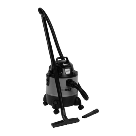
Fliegl VFW User manual

Operating instructions
VFW vacuum tanker
GB
We are Fliegl.

,

1
About these operating instructions
Dear valued customer,
These operating instructions will familiarise you with some of the functions of the vacuum tanker.
They merely contain basic information to enable rapid start-up of the vacuum tanker and do not replace the
detailed operating instructions.
It is therefore essential that you read all detailed information and warnings in the operating instructions.
1. Identification
Machine identification data
Manufacturer:
Fliegl Agrartechnik GmbH
Product:
Vacuum tanker
Type:
VFW 3000, VFW 4000, VFW 5000, VFW 6200,
VFW 7500, VFW 8600, VFW 10600, VFW 12000,
VFW 14000, VFW 16000, VFW 18000, VFW 20000,
VFW 22000, VFW 23000, VFW 25000, VFW 27500,
VFW 30000
Serial number:
WGJXXXXXXXXXXXXXX
1.1 Customer service
Please contact:
Fliegl Agrartechnik GmbH
Service Department
Bürgermeister-Boch-Straße 1
84453 Mühldorf am Inn, Germany
Telephone: +49 (0)8631 / 307 - 461
Fax: +49 (0)8631 / 307 - 550
E-mail: [email protected]
Internet: www.fliegl.com
1.2 Replacement parts
For replacement part orders, please contact:
Fliegl Agro-Center GmbH
Maierhof 1
84556 Kastl, Germany
Tel.: +49 (0)8671 / 9600 - 0
Fax: +49 (0)8671 / 9600 - 71
E-mail: [email protected]
Internet: www.agro-center.de
Formal details of brief instructions
Document no.:
1-006K06201.0
Version/revision:
1.0
Creation date:
05/06/2020
Last revision:
15/06/2020
Language of original operating instructions: German (Translation of original operating instructions)
Copyright Fliegl, 2020 All rights reserved.
Reproduction, in whole or in part, is only permitted with the approval of Fliegl.
We are constantly developing and enhancing our products and therefore reserve the right to make changes to
them without prior notification.
This may result in differences in the illustrations and descriptions in these operating instructions.

2
2. EC Declaration of Conformity
As stipulated in EC Machinery Directive 2006/42/EC, Annex II, 1.A (ORIGINAL)
Manufacturer:
Fliegl Agrartechnik GmbH
Bürgermeister-Boch-Straße 1
84453 Mühldorf am Inn, Germany
Person residing in the European Community authorised to compile the relevant technical documentation:
Kopold Gerald
Fliegl Agrartechnik GmbH
Bürgermeister-Boch-Straße 1
84453 Mühldorf am Inn, Germany
Description and identification:
Product: Fliegl vacuum tanker
Type: VFW 3000, VFW 4000, VFW 5000, VFW 6200, VFW 7500, VFW 8600, VFW 10600, VFW 12000, VFW
14000, VFW 16000, VFW 18000, VFW 20000, VFW 22000, VFW 23000, VFW 25000, VFW 27500, VFW 30000
Project designation: Vacuum tanker
Trade name: Fliegl VFW vacuum tanker
Function: A tanker (or tank trailer) is an agricultural machine for transporting/spreading liquid
manure or slurry on fields and grasslands.
It is expressly stated that this machine complies with all relevant provisions of the following EC directives:
2006/42/EC:2006-05-17 EC Machinery Directive 2006/42/EC
Source of the harmonised standards applied in accordance with Article 7(2):
EN ISO 4254-1:2009/AC Agricultural machinery –Safety –Part 1: General requirements (ISO 4254-1:2008)
EN ISO 4413:2010 Hydraulic fluid power –General rules and safety requirements for
systems and their components (ISO 4413:2010).
EN ISO 14121-1:2007 Safety of machinery –Risk assessment –Part 1: Principles (ISO 14121-1:2007).
EN ISO 13857:2008 Safety of machinery –Safety distances to prevent hazard zones being reached by upper and
lower limbs (ISO 13857:2008)
EN 1012-2:1996 Compressors and vacuum pumps –Safety requirements –Part 2: Vacuum pumps.
Mühldorf am Inn 15/06/2020
Place, date

3
3. User instructions
This manual provides information about the structure, function, operation and maintenance of the vacuum tanker and
ensures long, problem-free operation if it is carefully observed. Fliegl assumes no liability and honours no warranty for
damage and malfunctions resulting from failure to comply with the operating instructions.
3.1 Liability and damages
The product must only be operated by persons who are familiar with the operating instructions, the product and national
laws, directives and regulations relating to health and safety at work as well as accident prevention.
We accept no liability for personal or material damage caused, or contributed to, by untrained persons due to non-
compliance with regulations regarding health and safety at work as well as accident prevention.
Based on the specifications in these operating instructions, Fliegl Agrartechnik GmbH assumes no liability for direct or
consequential damage attributable to improper operation or maintenance. For your own safety, you should only use
original replacement parts and accessory products.
Fliegl Agrartechnik GmbH assumes no liability for the use of other products and any resulting damage. No claims for
modification of delivered products can be made on the basis of the information, images and descriptions provided in this
manual.
3.2 Duty to inform
These operating instructions are to be considered part of the tank trailer. If the machine is passed on to another party by
the customer, the operating instructions must also be passed on and the party receiving the machine must be instructed
regarding the regulations cited above.
4. Basic safety instructions
When driving on public roads, be aware of the following:
When driving on public roads, the provisions of the country-specific registration regulations must be observed. A licence is
required to operate agricultural trailers.
(The operator is personally responsible for the registration of the vehicle.)
Failure to observe the safety instructions and warnings can pose a risk to persons, property and the
environment.
Be aware of the legal requirements of your respective country.
Lost permit documents can only be replaced by agreement with the administrative authority specified below.
A duplicate certificate will be given to the customer by the administrative authority.
Before driving on public roads:
- Before travelling on public roads, ensure that the maximum permissible dimensions, weights as well as axle, drawbar
and trailer loads dictated by EU or national law are not exceeded.
- The tank openings must all be closed.
- The supporting mechanism must be fully retracted.
- For equipment with a connection for the tractor hydraulics, the hydraulic lines between the towing vehicle and tank
trailer must be disconnected or their actuation device locked.
- If the tank trailer is equipped with an overrun brake, the breakaway cable must be attached to the tractor.
- The steering axle must be locked when travelling straight ahead or reversing.
- The steering axle must be released shortly before turning.
All screw joints/connections must be checked prior to initial start-up.
Carrying persons on the tank trailer is prohibited.
The tank trailer can tip to the side in tight corners.
In the case of extended storage, note the following:
- Retract all hydraulic cylinders.
- Thoroughly lubricate all movable parts (risk of rust).
- If there is a risk of frost, empty the turbo filler and compressor (centrifugal pump).
- The line must be drained via the gate valve so that it and the valve etc. are not damaged by slurry.
4.1 Designated use
The Fliegl vacuum tanker is intended for general use in agricultural applications.
It is designed and suitable for transporting and spreading sludge, slurry, biogas fermentation residue etc.
Please contact the manufacturer regarding the trailer's suitability for conveying special transport media.
Always use a signaller when reversing (as required by German road traffic regulations).

4
5. Description of the machine
5.1 Functional description
The drive shaft powers a compressor which generates negative pressure (vacuum) in the tank container.
By connecting a suction hose to the quick coupler, the slurry can be sucked into the tank by means of the negative
pressure. A siphon and additional siphon prohibit over-suction in the slurry tank, thereby preventing contamination of the
compressor during the suction process. The filling speed can be increased with a turbo filler. The slurry is discharged by
means of the positive pressure, which is also generated by the compressor. The pressure relief valve (compressor) is
configured at the factory. The valve is factory-sealed to prevent manipulation of the setting. It stops the pressure rising
above the permissible value of 0.5 bar. A positive/negative pressure relief device is located at the top of the tank as
standard.
For large spreading widths, the output can be increased with the aid of a discharge accelerator.
To prevent excessive sloshing during travel, baffle plates are used in the vacuum tank.
5.1.1 Suction process
Suction: When the compressor is set to suction position, negative pressure is created in the tank container.
The resulting vacuum causes the substrate to be sucked into the tank.
In combination with the foam separator, the siphon prevents over-suction of slurry into the compressor.
5.1.2 Discharge process
Discharge: When the compressor is set to pressure position, air flows into the tank container.
The resulting positive pressure causes the substrate to be pressed into the spreader.
A pressure relief valve ensures that a maximum pressure of 0.5 bar is not exceeded during discharge.
1. Vacuum compressor
2. Compressor air outlet
3. Pressure relief valve
4. Foam separator
5. Pressure gauge for negative
pressure control
6. Siphon
7. Negative pressure
8. Suction valve
9. Suction line
1. Vacuum compressor
2. Compressor air inlet
3. Pressure relief valve
4. Foam separator
5. Pressure gauge for positive pressure
control
6. Siphon
7. Positive pressure
8. Slurry under pressure
9. Spreader

5
5.2 Layout of the machine
The following figure provides an overview of the most important components and assemblies and shows where they are
installed on the machine:
Fig. 1:Overview
5.2.1 Heat-resistant compressor (standard)
The slurry is sucked into the tanker due to the negative pressure created by the
compressor. The slurry is discharged by means of the positive pressure, which is
also generated by the compressor. (Switching via compressor changeover)
Fig. 2:Compressor
The maximum operating pressure of 0.5 bar must not be exceeded.
5.2.2 Fill level indicator (standard)
The fill level indicator primarily serves as orientation during filling and assists in
the discharge process.
The fill level indicator (needle) is a prerequisite for a tank counter,
which is connected to the fill level indicator on specific axle assemblies with ALB
regulators.
Fig. 3:Fill level indicator
Positive/negative pressure relief
device (5.2.5)
Filling dome preparation (5.2.6)
Siphon & additional siphon (5.2.7)
Pressure gauge (5.2.8))
Drawbar support
Hose holder & supply
connections
Draw gear
Drive shaft
Drawbar
Quick coupler (5.2.9)
Heat-resistant compressor (5.2.1)
Fill level indicator (5.2.2)
Supporting
mechanism
Parking brake
Axle assembly
Manway (5.2.3)
Dummy
flange
Hydraulic gate valve
(rear)
(5.2.4)

6
5.2.3 Manway (standard)
The manway serves as an entry point for performing necessary repairs or
cleaning work on the vacuum tanker.
Fig. 4:Manway
The container must be cleaned and well ventilated before/during any work in the tank. Open
all gate valves and covers. The container must be depressurised.
Caution: risk of suffocation in the case of insufficient cleaning or ventilation!
5.2.4 Hydraulic gate valve, rear (standard)
The hydraulic gate valve is used to open the container for discharging the slurry.
It is operated via the hydraulic control of the tractor or tank.
Fig. 5:Hydraulic gate valve
Never reach into the gate valve or stopcocks. Risk of crushing!
5.2.5 Pressure relief valve & positive/negative pressure relief device
(standard)
The pressure relief valve prevents the formation of overpressure inside the tank
during slurry discharge. The factory setting is 0.5 bar.
(The valve opens as of this pressure.) The valve setting must not be changed.
The negative pressure relief device opens in the case of excessive negative
pressure during the suction process.
Fig. 6:Pressure relief valve / compressor
Fig. 7:Positive/negative pressure relief
device
5.2.6 Filling dome preparation (standard)
The filling dome features a fixed cover as standard.
A mechanical or hydraulic filling mechanism can be retrofitted at a later stage.
Fig. 8:Filling dome preparation
The container must be cleaned and depressurised before performing any retrofit work.
The filling dome must not be used as an entry point.
Only the designated manway must be used for this purpose.
5.2.7 Siphon & additional siphon (standard)
A siphon and additional siphon prevent over-suction and thus contamination of
the compressor during the filling process. As soon as the container fills up, the
slurry lifts the ball into the air inlet opening and seals it.
Fig. 9:Siphon

7
5.2.8 Pressure gauge (standard)
The container pressure must be checked on a regular basis via the pressure
gauge.
Fig. 10:Pressure gauge
Maximum container pressure 0.5 bar
5.2.9 Quick coupler (standard)
The vacuum tanker can be filled by connecting a suction hose to the quick
coupler.
There are two different quick coupler systems:
Italian coupling system (standard)
Perrot coupling system (optional)
Fig. 11:Quick coupler
5.2.10 Drawbar suspension (standard or optional)
The draw gear can be mechanically/hydraulically adapted to the coupling
height. There are 2 different versions:
Tank tipping cylinder with suspension
Tank tipping cylinder without suspension
Fig. 12:Drawbar suspension
5.2.11 Silencer with oil separator (standard or optional)
The silencer reduces the noise level of the compressor. It features an integrated
drain cock for discharging the collected oil.
Fig. 13:Silencer & oil separator
5.2.12 Filling dome, mechanical or hydraulic (optional)
External filling of the tanker can be performed via the mechanically/hydraulically
opening filling dome.
Fig. 14:Filling dome,
mechanical/hydraulic
Risk of crushing!
The container must be depressurised before opening the dome cover.
5.2.13 Turbo filler (optional)
The turbo filler increases the filling speed during the suction process.
It is operated via the hydraulic control of the tractor or tank.
Fig. 15:Turbo filler

8
5.2.14 Suction nozzle (optional)
The suction nozzle –in combination with a docking station –enables
convenient suction without having to leave the tractor cab.
It is operated via the hydraulic control of the tractor or tank.
Fig. 16:Suction nozzle
5.2.15 Hydraulic compressor changeover (optional)
The suction/discharge function can be controlled from the tractor cab via the
hydraulic compressor changeover.
It is operated via the hydraulic control of the tractor or tank.
Fig. 17:Compressor changeover
5.2.16 Internal agitator(optional)
The internal agitator helps to prevent the formation of sediment at the bottom of
the tanker. In addition, the slurry is homogenised by the air supplied from the
compressor.
There are 2 versions of the agitator:
Internal pneumatic agitator ()
Internal hydraulic agitator ()
Fig. 18:Internal agitator
5.2.17 Control block –load sensing / constant flow
Selected tank functions can be actuated via the hydraulic control block. The oil
is supplied either via load sensing or constant flow from a tractor control unit.
Fig. 19:Control block
5.2.18 Lighting options
Side marker lights, right/left (yellow)
Clearance lights, rear (white/red)
Position lights, front (white)
LED rear light
Fig. 20:Lighting
5.2.19 Sprinkler nozzle (special equipment)
The sprinkler nozzle facilitates application of the substrate on inaccessible
inclines.
The sprinkler nozzle features hydraulic adjustment:
Function 1: up/down Function 2: pivot
Fig. 21:Sprinkler nozzle
The pivot function does not offer continuous, unrestricted rotation.
Be careful not to damage the attached hydraulic lines.

9
5.3 Weights –standard equipment
Drawbar load
(approx. kg)
1,000
1,000
1,000
1,000
1,000
2,000
2,500
2,000
2,000
2,500
3,000
4,000
2,000
2,000
2,500
2,000
2,500
3,000
4,000
3,000
4,000
2,000
3,000
4,000
3,000
4,000
Total weight
(approx. kg)
4,600
5,000
7,000
8,000
9,000
9,000
10,500
11,000
12,000
12,500
13,000
14,000
14,000
16,000
18,500
20,000
20,500
21,000
22,000
23,000
24,000
29,000
30,000
31,000
33,000
34,000
Type
Version
3000
Single-
axle
x
4000
Single-
axle
x
5000
Single-
axle
x
6200
Single-
axle
x
x
7500
Single-
axle
x
x
8600
Single-
axle
x
x
Tandem
x
10600
Single-
axle
x
x
x
Tandem
x
x
12000
Single-
axle
x
x
x
Tandem
x
x
x
x
x
14000
Single-
axle
x
x
Tandem
x
x
x
x
x
16000
Tandem
x
x
x
x
x
18000
Tandem
x
x
x
x
20000
Tandem
x
x
Tridem
x
x
x
22000
Tridem
x
x
x
x
23000
Tridem
x
x
25000
Tridem
x
x
x
x
x
27500
Tridem
x
x
30000
Tridem
x
All trailers are in basic condition. The weight specifications comply with German traffic laws (StVZO). It is possible that different vehicle class
provisions exist in different countries. The mass figures are version-specific and may deviate.
Details are provided on the type plate, for instance. The weights and drawbar loads were partially determined by calculation and may differ in
practical applications. The centre of gravity and thus the drawbar load may shift depending on how the load is distributed.
If additional devices are used, the payloads, empty loads and axle loads will change.
6. Transport and installation
6.1 Supply and installation
6.1.1 Draw gear –connection
The ordered flange coupling is mounted on the trailer. Check the towing coupling on the tractor to ensure it is fully
functional and securely hitched, and adjust the trailer height to match the towing vehicle.
6.1.2 Establishing the electrical connection
See section 8.10
6.1.3 Compressed air supply
See section 9.1.2
6.1.4 Establishing hydraulic connections
See section 8.11

10
7. Start-up
7.1 Check before start-up
Check to ensure that all safety devices (covers, panels etc.) are in proper condition and are attached to the trailer in
protective position.
- Lubricate the tank trailer according to the lubrication schedule.
- Then check all screw connections specified below for tightness.
- Check the tyres to ensure the air pressure is correct (as per manufacturer specifications).
- Adjust the tyre pressure according to the application.
- Check the oil level of the hydraulic system and inspect it for leaks.
- Check the wheel nuts.
- Check the oil level of the compressor.
- Check the container closures for dirt or damage.
8. Preparation and setup
8.1 Draw gear –mechanically adjustable (standard)
The draw gear can be mechanically adapted to the coupling height. Preset at the factory!
Procedure: A predefined height can be set by moving the threaded bolts.
8.2 Draw gear –hydraulically adjustable (optional)
The draw gear can be hydraulically adapted to the coupling height.
Procedure
Tank tipping cylinder with suspension: This variant is hydraulically sprung and the coupling height can be changed by
reducing or increasing the oil level in the cylinder.
Tank tipping cylinder: The coupling height can be changed by reducing or increasing the oil level in the cylinder.
For tank tippling cylinder with suspension: The cylinder must never be fully extended or retracted
while driving. Otherwise, the suspension function will not work.
8.3 Overrun brake mechanism
See section 10
8.4 Compressed air brake system with ALB, brake force regulator
Selecting the operating mode, adjusting the trailer
load status
"Release" operating mode for moving the uncoupled tank
trailer is triggered via the trailer release valve. The button
must be pushed in for this purpose.
Fig. 22:Compressed air brake system
When using the trailer brake valve in combination with a manually adjustable brake force regulator without release
position, a trailer release valve is employed.
8.5 Spindle brake / parking brake
Applying the brake:
To activate the spindle brake, you must turn the crank in clockwise direction.
Do this until you feel resistance.
Releasing the brake:
To release the brake, you must turn the crank in the opposite direction (anti-
clockwise) until the tension on the brake cable is released. (The cable must sag
slightly.)
Fig. 23:Spindle brake
Trailer release valve
button

11
8.6 Hand brake lever (overrun brake) –parking brake
Applying the brake:
To activate the hand brake, pull the actuating lever towards the drawbar eye. The
brake locks automatically.
Releasing the brake:
Press in the button at the tip of the actuating lever to unlock the brake. Move the
lever towards the container while keeping the button depressed. If the actuating
lever is equipped with an extension, unfold this extension. The extension triggers
the button and releases the brake (see detail image).
Fig. 24:Overrun brake
8.7 Farmer stop –parking brake
Applying the brake:
To activate the parking brake, pull the actuating lever towards the drawbar eye. The
lever must be pulled tight to ensure that the brake is correctly applied. In addition,
mechanical and positive engagement of the saw tooth profile on the crown must be
ensured.
Releasing the brake:
Briefly pull the actuating lever towards the moving panel.
This releases the locking mechanism and disengages the brake.
Fig. 25:Spindle brake
Safeguard:
To prevent accidental disengagement of the brake, the locking mechanism features a safeguard,
which is activated/deactivated through folding.
8.8 Hydraulic brake (option not for Germany)
8.8.1 Hydraulic brake system
The trailer can be equipped with an optional hydraulic brake system. The brake line is connected to the hydraulic brake
connection of the towing vehicle. The hydraulic cylinders operate the wheel brakes via bell cranks.
8.8.2 Hydraulic brake with load adjustment valve
When hydraulic brake systems are connected to the tractor's hydraulic brake system, the trailer must be braked via the
tractor's brake system.
The brake pressure must not exceed 120 bar (12,000 kPa). An emergency brake system must be fitted, e.g. farmer stop
brake with connecting cable to the tractor; a fixed connection to the tractor, or similar, must be established during driving
operation.
Single-action connection via hydraulic coupling (SVK) or screw socket
- Test the brake function before driving with the trailer.
- The response characteristics of the brake can be altered by means of a throttle check valve in the tractor
brake system (if fitted).

12
8.9 Installing forced steering on the towing vehicle (optional)
The customer mast adapt the forced steering individually to each towing vehicle. This means that the settings must be re-
adapted every time the towing vehicle is changed.
The dimensions on the Ø 80 ball head coupling and the clearances according to ISO 500 and ISO 730 must be applied.
Procedure
Mounting of the steering cylinder at the same axial and
vertical height as the ball head coupling on the towing
vehicle (tractor) with 250 mm clearance (
5).
Fig. 26:Installation layout for forced steering
- At maximum steering angle, the tyres must not touch the frame or other parts of the vehicle.
- Check the axle stops and adapt them to the tyre size if necessary.
- At maximum steering angle of the hydraulic cylinders with coupling (52°), ensure sufficient space from the panelling on
the outside and from the flange coupling on the inside.
- The cylinder protection (on the side of the traction bar) must be checked and adjusted for every towing vehicle type; if
necessary, double the cylinder protection until the wheels of the towing vehicle (tractor) make contact at maximum
steering angle.
Attention! The stopcocks on the steering axle must be opened before commencing travel, otherwise
the hydraulic cylinders may be damaged.
When coupling the towing vehicle to the trailer, approaching in exactly the same position as when uncoupling will not
work. The forced steering can therefore be re-coupled as follows.
Procedure
- Approach the trailer with your towing vehicle as straight as possible.
- Couple the towing vehicle to the trailer via the trailer coupling.
- Release the lock at the end of the forced steering cylinders by lifting up the lever.
- The cylinder can now move freely and can be easily connected to the towing vehicle.
- Fold the lock lever back down again.
- Drive the tractor/trailer combination forwards slowly until the vehicles are in a straight line. The forced steering
cylinder lock should re-engage during this process.
The tanker is delivered with the stopcocks on the steering axle closed. They must be opened before
commencing travel, otherwise the hydraulic cylinders may be damaged.
Setting up the system
1. Open stopcocks 1, 2 and 3
2. Drive the tractor/trailer combination forwards slowly until the vehicles
are in a straight line
3. Apply a pressure of 50 bar to the system
4. Close stopcock 1
5. Close stopcocks 2 and 3 one after the other
6. Check whether the forced steering is functioning correctly at full
steering lock
7. If not, there may be air in the system
Fig. 27:Forced steering valves (tandem)
Note: The system is filled in the factory.
Pressure
gauge
1
2
3

13
8.10 Electrical systems
Before each journey, check to ensure the electrical light system is working properly.
The tank trailer must only be used when the lighting system is connected and operational.
Lighting connection Procedure:
Power is supplied by the towing vehicle via plug connection(s).
Plug connection for lighting (7-pin connector, ISO 1724)
Control current via (12V=) connector.
Fig. 28:7-pin connector
Control valve connection Procedure:
Power is supplied by the towing vehicle via plug connection(s).
Plug connection for control panel (3-pin connector, DIN 9680)
Control current via (12V=) connector.
Fig. 29:3-pin connector
8.11 Hydraulic system –standard constant flow version (open centre, OC)
Coupling:
Before coupling, deactivate the PTO and set the
lever on the control device to floating position
(depressurised).
- Ensure that the couplings are clean.
Constant flow:
- (1) Pressure connection
- (2) Return connection
Fig. 30:Hydraulic connection
Dual-action control device
Connect the pressure line (1). (The pressure line leads to the pressure filter on the machine.) Connect the oil return
hose (2) to the oil return line (T) of the towing vehicle, as in the case of the single-action control device.
1
2

14
9. Use and operation
9.1 Trailer operation
9.1.1 Setting up the trailer coupling on the towing vehicle
Move the towing device of the towing vehicle to the correct height.
Position the trailer coupling (A) on the towing vehicle so that the tank
trailer is horizontal when it is hitched
and so that, when the trailer is attached, there is sufficient space
between the drive shaft and the drawbar (A1), especially during tight
turns.
Fig. 31:Setting up the trailer coupling on the towing
vehicle
Ball head coupling
The ball head coupling must only be coupled with an approved coupling ball (ball diameter 80 mm) that is suitable for
ensuring safe attachment and locking.
9.1.2 Coupling the trailer
1. Move the towing device of the towing vehicle or the drawbar eye of the trailer to the correct height.
2. Open the towing device on the towing vehicle.
3. Move the towing vehicle backwards until the drawbar eye engages in the towing device.
4. Secure the towing vehicle against rolling away (parking brake) and turn off the engine.
5. Check whether the towing device is engaged.
6. Establish the electrical connections and connect the service brake.
Procedure:
Connect the standard couplings for the dual-line
compressed air brake system.
Red –supply line
Yellow –brake line
Fig. 32:Compressed air supply
Hydraulic connections
- Connect all hydraulic lines to the towing vehicle in pairs (double action).
- For labelling to identify connection points, see the stickers on the vehicle and on the couplings.
Attaching the drive shaft
Attach the drive shaft between the tractor and the vacuum
tanker.
Ensure that the swivel head audibly engages in the PTO stub.
Fig. 33:Attaching the drive shaft
Before assembly, check the minimum length of the drive shaft. The minimum length is the smallest
possible distance between the tractor PTO and the connection point on the trailer. An excessively long
drive shaft can buckle during operation or even break off. You must also read the drive shaft
operating manual carefully and follow the contained instructions.
9.1.3 Conducting a trial run
After the machine is set up and prepared and before work begins, a trial run must be conducted in unloaded condition.
Procedure
- Turn on the machine as specified
- Perform all functions of the machine individually.
Coupling:
1. Yellow –brake line
2. Red –supply line
Uncoupling:
1. Red –supply line
2. Yellow –brake line
A
A1

15
9.2 General safety and operating instructions
The following section contains some general notes on safety and operation for working with the tank trailer, repeated and
summarized together for better clarity:
- In addition to the information in these operating instruction, you must also observe the generally applicable safety and
accident prevention regulations.
- Attachments must only be used if all safety devices are in place and in the protective position.
- Before starting work, you should familiarise yourself with all devices and controls as well as with their function. It is too late to
do so once work has started.
- When handling slurry, be aware that the gases produced are highly toxic, and explosive when combined with oxygen. Naked
flames, light testing sparks, and smoking are therefore forbidden.
- During flooding or alternate flooding operations, particular care should be taken due to gas formation in the area of the open
valve to the trough mixer, or main container or cross-channels, as well as at the stirring and removal positions when the
agitators or pumping stations are active.
- Always ensure sufficient ventilation and/or air supply when working with slurry.
- Only perform maintenance work when the containers are empty.
- The weights and loads specified on the type plate must be observed.
- Never park tanks on the supporting mechanism when loaded.
- The drive shafts must meet the requirements of the attachment manufacturer.
- Do not stand on the drive shaft.
- Do not enter the work area while parts (drive shaft) are still rotating.
- Before first-time start-up, move all protective devices to the safety position.
- There must be no persons in the danger zone (suction nozzle) during slurry application/filling.
- Leave all gate valves open during storage in winter. Risk of frost damage!
- The compressor must not be overheated.
9.3 Compressor changeover –Battioni
DISCHARGE
CONTAINER DEPRESSURISED
SUCTION
Fig. 34:View of adjustment lever
9.4 Compressor changeover –Hertell
DISCHARGE
CONTAINER DEPRESSURISED
SUCTION
Fig. 35:View of PTO stub

16
9.5 Operation via control panel (control symbols)
If your tanker features a hydraulic control block, specific functions are operated via a control panel. The
following symbols represent the relevant functions.
Fig. 36:Control panel
Fig. 37:Storage box –accessories
When disconnected, the control panel must be placed in the designated storage box to protect it against
moisture.
Symbol
Description
Symbol
Description
Drawbar –UP
Drawbar –DOWN
Suction nozzle –UP
Suction nozzle –DOWN
Suction nozzle valve –OPEN
Suction nozzle valve –CLOSE
Dome cover –OPEN
Dome cover –CLOSE
Compressor changeover –
DISCHARGE
Compressor changeover–SUCTION
Discharge valve –OPEN
Discharge valve –CLOSE
Turbo filler –ON / OFF
Internal hydraulic agitator –ON / OFF
Sprinkler nozzle –UP
Sprinkler nozzle –DOWN
Sprinkler nozzle –ROTATE left
Sprinkler nozzle –ROTATE right

17
9.6 Operation via tractor control units
If the tanker does not feature a hydraulic control block, all functions are operated directly via tractor
control units.
Summary of tank functions with pressure sequence valve:
If a pressure sequence valve is installed, the following 3 functions can
be controlled with one tractor control unit:
Suction nozzle UP/DOWN
Suction nozzle valve
Compressor changeover
Fig. 38:Hydraulic connection / pressure sequence
valve
Using the existing stopcocks, you can preselect whether one of these
functions is to be performed individually when actuated via the tractor
control unit, or whether all functions are to be carried out consecutively.
Fig. 39:Stopcocks
The functions are performed consecutively when the required pressure is reached.
If oil pressure is applied in direction 1 on the tractor control unit (all
stopcocks open on the pressure sequence valve), the functions are
carried out in the following order:
1. Hydraulic compressor changeover switches to suction.
2. The suction nozzle lowers itself.
Fig. 40:Hydraulic connection
Fig. 41:Hydr. compressor changeover
Fig. 42:Suction nozzle

18
3. The suction valve opens.
If the double-action control unit is operated in the other direction
(direction 2), the functions are performed in reverse order.
Fig. 43:Suction nozzle / suction valve
9.7 Operating the turbo filler
9.7.1 Operation via tractor control unit
An oil flow rate of approx. 80 l/min is required to operate the turbo
filler.
The hydraulic connections must be attached to the tractor as follows:
Connection 1: Supply (small hose diameter)
Connection 2: Return (large hose diameter)
The turbo filler can be activated or deactivated directly via a stopcock in
the system,
provided that the required oil flow rate exists.
Fig. 44:Turbo filler
Fig. 45:Hydraulic connection
Connection 2 must be attached to a pressureless port on the tractor.
9.8 Overview of compressor speed
Compressor speed
(specification on type plate)
Recommended working speed
540 rpm version
350 to 400 rpm
1000 rpm version
850 to 900 rpm
Table of contents