Fliptop Slider Quick setup guide

Edition 1.2
www.iptop.se
info@iptop.se
2020
Slider
Safety and Assembly instructions

2
Thank you for purchasing a Fliptop Slider.
This document includes assembly instructions for the Fliptop Slider system. There are variants
depending on length, width and number of arches.
In case of uncertainty or questions, we or the reseller would be happy to provide you with support.
Important
Transport damage must be reported to
the carrier. It is important to check the
packaging when the goods arrive, if
it is damaged, a notication must be
made to the driver at the time of
delivery. It is the carrier that is
responsible for damage that occurs on
the goods during transport. The
mounting must be done according to
the mounting instructions for the
material warranty to apply.
Warranty
There is a 1 year material and function
guarantee from us. For the warranty to
apply, the product must be mounted
according to our instructions.
SafetySafety
The safety instructions must be read carefully before using the Fliptop Slider, as moving
parts move with the help of electric motor or manual power, without knowledge, serious
personal injury and damage to the system can occur.
Read the manual carefully!

2 3
Table of contents
Operating instructions for Fliptop Slider 4
General information 4
Operating instructions 4
Opening and closing the Fliptop Slider Manual (802-002) 4
Opening and closing of Fliptop Slider with electrical motor (802-003) 5
Important information 5
Automatic start with Time relay 5
Safety instruction 6
Performance of vehicles with Fliptop Slider 6
Ice and snow 6
In strong wind 6
Maintenance 6
Installation of Fliptop Slider 7
Mounting bracket for drive beam 8
Mounting drive beam 9
Mounting of the wire wheels 11
Mounting of the wire 12
Tensioning off the wire 13
End position adjustment 14
Drive unit 16
MANUAL 16
ELECTRICAL 17
Adjustment of automatic rear closing 18
Adjustment of stop arm 20
Wire cutting 21
Mounting option on drive beam 22
Post tensioning of wire 23
Wind protection Z-prole 24
Wind protection Exterior 25
Wind protection Inside 26
ELECTRICAL SCHEME 27
Replacement of fuse 40A 28
Drawings 29
Sparepartslist 31

4
Operating instructions for Fliptop Slider
General information
Fliptop Slider is a roof system to cover mainly tipper trucks and containers. Consisting of a
number of arches joined by a steel wire and covered by PVC cloth. The Fliptop Slider is opened
and closed manually, or with an electric motor. Fliptop Slider is mainly intended for the coverage of
tipper trucks and containers. This however does not exclude other uses.
Operating instructions
Read this documentation and familiarize yourself with the equipment before use. Fliptop Slider is
powered by electric motor 24V DC or a manual crank. The motor-driven alternative is controlled
by a remote control and/or buttons on the electrical cabinet. The manual option is operated with a
crank.
Opening and closing the Fliptop Slider Manual (802-002)
The roof opens and closes with a crank that sits on the drive beam. To be able to crank, push the
crank out of the backrest.

4 5
Opening and closing of Fliptop Slider with electrical motor (802-003)
To operate the sliding roof the main switch must be turned on. The roof is opened or closed by
remote or with push buttons on the electrical cabinet, normally the truck must be connected, or an
extern 24V battery is needed to operate the roof.
Fliptop Slider uses a power card that senses the power consumption, when the roof comes to a
stop, the power card senses the load and breaks the power. You can’t start in the same direction
as the power card cut the power, you can only move the roof system in the opposite direction in
this case. The power card inside the electrical cabinet is preprogrammed. Should the roof stop
earlier, please check that the load does not reach the platform edge, or lies against the Fliptop
Slider System.
The remote control is started by holding down the On button for a few seconds, when the middle
LED lights up green = The remote control is active. The remote control turns o with the O button
or automatically after a while to save battery. The buttons with arrows open and close the ceiling.
The roof can also be operated with the push buttons on the electrical cabinet. There is a main
switch on the back of the remote control as well as the electrical cabinet. It should always be in the
”on” position, the transmitter will not drain the battery.
When opening and closing the Fliptop Slider, you must be vigilant and make sure that there
is no chance of personal injuries. The electric or manually driven movements are very strong and
can cause very serious damage if you get pinched or hit by the system. If your Fliptop slider has a
remote control be extra careful, so that no one accidentally accesses it and maneuver when
someone is near moving parts. It is also important to not open or close while driving. If you need to
perform service or other work on the system, it is imperative to disconnect the power. If the system
is locked with straps, do not forget to release them before operating the Fliptop Slider.
Important information
Strong winds can seriously damage the system. Therefore, tighten down the roof with straps under
strong wind. It is important to be careful when loading and unloading so that the loaded material
does not end up on the roof of the system. If the cargo lls the entire cargo space and tends to
collapse into a coherent mass there is a risk of a vacuum forming, this can bend the arches and
seriously damage your system, if this is a risk, open then the ceiling to let in air before unloading.
When loading and unloading masses of heavy stone, roots or anything else that stands up, it is
important that the load does not come into contact with the roof system, it prevents opening and
closing of the roof. NOTE it is important to open the roof before tipping so that the load does not
get stuck in the roof, because the system can be damaged then.
Automatic start with Time relay
Slider has a time relay which can be switched on, this then opens the roof when tilting or when
opening the back door, so that the Slider will not be crushed by the tailgate/ tailboard. Operation of
the tailgate and when tipping should always be supervised to be able to cancel if something
unexpected should happen. The manufacturer accepts no liability for damage that occurs if
the time relay or other technology would not operate the slider system during tipping or
opening.
Main power switch
should always be ”on”

6
Safety instruction
The equipment may only be operated by personnel with sucient knowledge of the equipment and
have an understanding of the risks arising when operating the system. The minimum requirement
for operating the system is a review of this documentation and a review of the equipment before
any work with it starts.
For service and maintenance, electricity must be switched o so that the equipment cannot run, as
there is a high clamping risk when operating the equipment.
Please note that the operator must always be careful not to cause damage to the equipment or
harm to people nearby.
Performance of vehicles with Fliptop Slider
Prior to transport, make sure that the tarpaulin roof is closed or completely open. It is not permitted
to drive with the roof partyly open. The roof can be damaged.
Ice and snow
Before opening or closing, snow and ice must be removed. Fliptop Slider is not designed for much
snow, max 10cm when the roof is closed, when the roof is completely open, it can withstand more
snow.
In strong wind
We do not recommend opening the ceiling when it blows more than 25m per second, as it can
damage the system.
Maintenance
We recommend that the Fliptop Slider system be inscpected once a week when using the system
continuously.
CONTROL POINTS:
• That the tarpaulin is not damaged.
• That the tarpaulin is fastened to the system
• That no bolts or rivets are missing.
• The tarpaulin is clean of debris and loads.
• That the wire is tensioned enough. If not tighten the wire.
If you nd damage, it is important to repair,
Contact your nearest dealer or workshop if you have any problems.
Please note
that the roof must either be fully
open or closed when driving the vehicle.

6 7
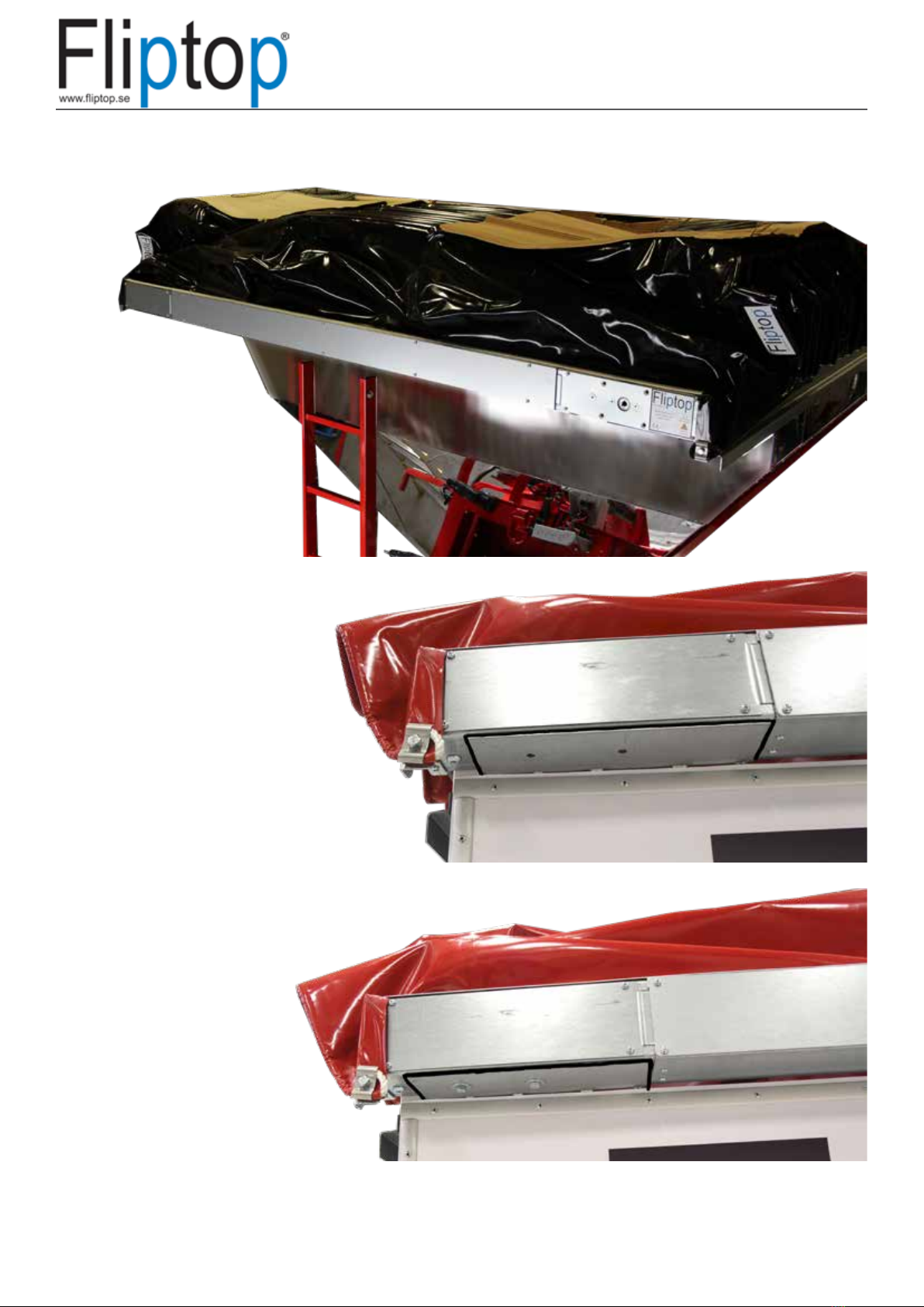
Installation of Fliptop Slider
Fliptop Slider is delivered pre-assembled and tested by us, for easy mounting on your atbed truck
or container. All parts to be used are included. Note that it may be necessary to make some ad-
justments to t your tipper truck or container as there are many dierent designs. It is important to
ll the order form carefully for a better t and easier assembly.
Fliptop Slider is delivered in two versions, manual opening with crank or motor operation, and
there are also dierent closing alternatives. Manual closing with straps or Automatic rear closing
with a tilt bow.There are several heights on the arches from straight to 600mm high. Standard
height is 300mm. All of these parameters make the content of the delivery varies.
Example of delivery
8
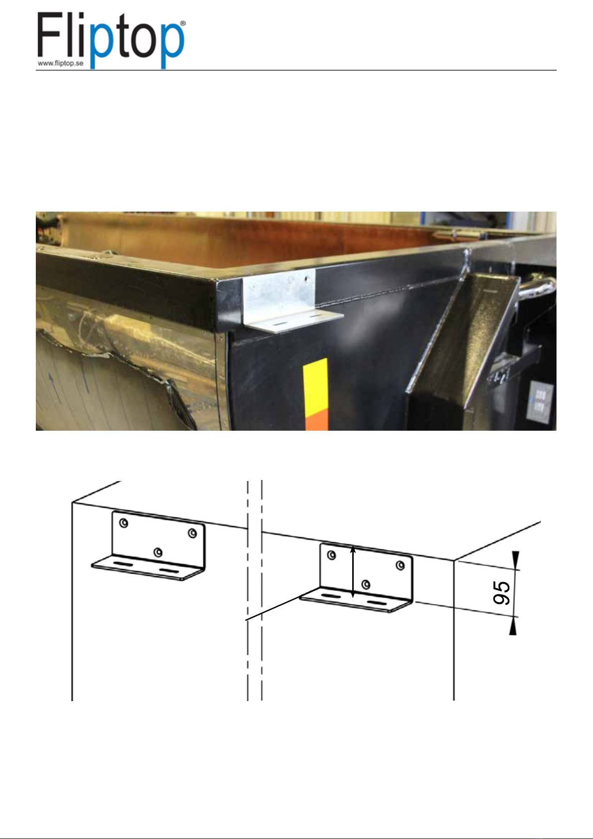
95
Mounting bracket for drive beam
The brackets for the drive beam are mounted according to the accompanying instructions.
Brackets mounted either with countersunk screw M8x20 or welded to the platform, it is important
that they are in parallel with the platform body side.
The measurement is taken
from the top of the platform
body to the bracket
95

8 9
Center the drive beam
Mounting drive beam
Lift the entire package up on the platform body top, remove the packaging from the Slider sys-
tem and release the wire so that the drive beam can be lifted down and placed on the drive beam
brackets, without loosening the wire locks on the wire.
34 34
Nr.
Ant
Ändring
Datum
Inf.
Godk.
10
A
98765
B
C
D
4321
A
B
C
D
E
F
G
H
1098765
E
F
4321
G
H
Godk.
Skala
1:15
ISO 2768-C
Tolerans där annat ej anges
~
SE-380 42 Målerås
SWEDEN
Tel: +46 481 31222
Konstr.
Ritad
Format
Ytjämnhet
Vikt
Ytbehandling
Dat.
Ritn.nr
802-001
Fliptop Slider utan drift
JÅG
A3
52.37 kg
This drawing, or parts thereof, may not be reproduced in any form, by any method,
for any purpose, without permisson of Målerås Mekaniska AB
Revision
Flatbed / Container
Drive beam
10
The drive beam is screwed in with two bolts on each side. 4 X M8X20 and 4 X BRB 8.5x40x3.

10 11
40
Nr.
Ant
Ändring
Datum
Inf.
Godk.
A
B
C
D
E
F
G
H
I
J
K
M
L
M
L
K
J
I
H
G
F
E
D
C
A
B
1918171615141312111098765431 2
1918171615141312111098765431 2
This drawing, or parts thereof, may not be reproduced in any form, by any method,
for any purpose, without permisson of Målerås Mekaniska AB
Godk.
Skala
1:20
ISO 2768-C
Tolerans där annat ej anges
~
SE-380 42 Målerås
SWEDEN
Tel: +46 481 31222
Konstr.
Ritad
Format
Ytjämnhet
Ersatt av
Ytbehandling
Dat.
Ritn.nr
A0
337.002 kg
Revision
Mounting of the wire wheels
The position of the wire wheels is determined when ordering the Fliptop Slider. It comes with an
instruction where to place the wire wheel to order. The bracket for the wire wheels should be
attached CC 40mm from top edge of the platform body to the holes in the bracket, then the wire
will end up 3mm below the top edge of the platform body.
If your system does not have automatic rear closing, follow the mounting instructions but
ignore the instructions for the chain and tilt arch, in the automatic rear closing solution.
Nr.
Ant
Ändring
Datum
Inf.
Godk.
10
A
98765
B
C
D
4321
A
B
C
D
E
F
G
H
1098765
E
F
4321
G
H
Godk.
Skala
1:10
ISO 2768-C
Tolerans där annat ej anges
~
SE-380 42 Målerås
SWEDEN
Tel: +46 481 31222
Konstr.
Ritad
Format
Ytjämnhet
Vikt
Ytbehandling
Dat.
Ritn.nr
A3
0.0 kg
This drawing, or parts thereof, may not be reproduced in any form, by any method,
for any purpose, without permisson of Målerås Mekaniska AB
Revision
Nr.
Ant
Ändring
Datum
Inf.
Godk.
10
A
98765
B
C
D
4321
A
B
C
D
E
F
G
H
1098765
E
F
4321
G
H
Godk.
Skala
1:10
ISO 2768-C
Tolerans där annat ej anges
~
SE-380 42 Målerås
SWEDEN
Tel: +46 481 31222
Konstr.
Ritad
Format
Ytjämnhet
Vikt
Ytbehandling
Dat.
Ritn.nr
A3
4410.7 kg
This drawing, or parts thereof, may not be reproduced in any form, by any method,
for any purpose, without permisson of Målerås Mekaniska AB
Revision
Example wire wheels without
automatic rear closing
Example wire wheels with
automatic rear closing
M10 MF6S M8 M6S

12
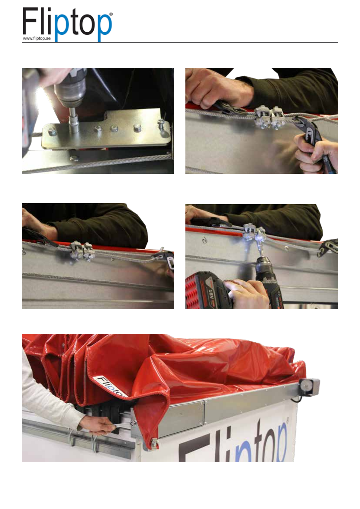
Mounting of the wire
Screw the cover and the wire wheel into the
bracket, make sure the wire is not tangled
together.
Thread the wire around the wire wheel. Place the two washers between the cover and
wire wheel. Thread through the bolt.
22
44
Place the wire wheel with the wire in cover.
NOTE! two washers
11
33
12 13
Loosen the two wire locks around the wire and
tighten it rmly.
Screw the two wire locks around the wire as in
the picture, while you tighten it.
Tensioning o the wire
Loosen the bolts to the wire holder on the end
arch on both sides so that the wire goes freely
through the system.
Tighten the wire by pulling at both ends of the
wire with maximum manual power.
Tighten the wire with the built-in wire tensioner on the drive beam. NOTE! Do not span the wire.
Appropriate tension is reached when the wire hangs down approx. 20-30mm on a 6 meter
system.(Post-tensioning may be needed)
1122
3344
55

14
Tighten the Slider system with the help of manual power so that
the end arch ends up close to its nal position, but without the tilt
arc with automatic closing closes.
End position adjustment
It is important that the wire locks come as close to the end arch as possible, see picture above.

14 15
Check that the Fliptop Slider stands
straight by measuring on both sides of
the end arch to the desired end
position.
Screw the end arch into the wire
bracket on both sides of the end arch.
It is important that the wire ends in the
grooves in the wire holder.
This is a good example of a good
positioning of the wire locks against
the end arch adjacent to the wire
wheel.

16
Drive unit
MANUAL
Fit the lock to the crank, then fas-
ten the crank, or alternatively cut
it to the desired length and tighten
the stop screws.

16 17
ELECTRICAL
The electric motor is mounted on the drive beam with 4 X M8X20 and 4 X M8 BRB with
the motor facing the center.
We recommend lubricating the shaft with grease before mounting.
The shaft with wedges are packed separately.
Fit the engine cover. When mounting, the motor protective cover must be clamped
between the aluminum strip and the drive beam bracket.

18
Adjustment of automatic rear closing
For the automatic closing to work well, the springs may need to be adjusted. The springs that lift
up the tilt arch with automatic closing should be as weak as possible. The force should only just be
able to lift up the tilt arch of the automatic rear closing. There are many possibilities to adjust the
springs.
The spring can be repositioned to reduce or increase the force.
The spring must be adjusted so that the automatic rear closing knocks down where the
wire wheel ends.
If the automatic rear closing goes down too soon, extend the chain between the spring and the
rocker. If the back end of the automatic rear closing goes down too late, shorten the chain
between the spring and the back end.
NOTE. It is important not to have the chain and springs too tight, as they tend to reverse
the Slider system.

18 19
When the back end of the automatic rear closing closes softly, it will look like this.
When the automatic rear closing is adjusted correctly, the s-hooks should be pinched.When the automatic rear closing is adjusted correctly, the s-hooks should be pinched.
1122
3344

20
Adjustment of stop arm
Adjust where to put the stop arm, it should be a gap of approx. 5CM.
Table of contents
Popular Industrial Equipment manuals by other brands

KTR-Group
KTR-Group KTR-STOP M-A-F B Series Operating & assembly instructions

Innova
Innova PantoVision T2 USER INTERFACE MANUAL

schmersal
schmersal AZM300Z-I2-ST-1P2P-T Operation instructions

Linn-High-Therm
Linn-High-Therm HT-1500-GT-VAC Special GRAPHITE operating instructions

Eaton
Eaton PKE-XTUACP-36 Instruction leaflet

Grundfos
Grundfos TPE 2 Series instructions


