HYTROL C Manual

2
●Table of Contents
Warning Signs . . . . . . . . . . . . . . . . . . . . . . .2
INTRODUCTION
Receiving and Uncrating . . . . . . . . . . . . .3
INSTALLATION
Installation Safety Precautions . . . . . . . .3
Support Installation . . . . . . . . . . . . . . .4-5
Ceiling Hanger Installation . . . . . . . . . . .6
Belt Installation . . . . . . . . . . . . . . . . . . . .7
Electrical Equipment . . . . . . . . . . . . . . . .8
OPERATION
Operation Safety Precautions . . . . . . . . .9
Conveyor Start-Up . . . . . . . . . . . . . . . . .9
Sequence of Operation . . . . . . . . . . . . . .9
Belt Tracking . . . . . . . . . . . . . . . . . .10-11
MAINTENANCE
Maintenance Safety Precautions . . . . . .12
Reducer Maintenance/Lubrication . . . . .12
Bearing Lubrication . . . . . . . . . . . . . . . .12
Chain Lubrication . . . . . . . . . . . . . . . . .12
Drive Chain Alignment and Tension . . . .13
Trouble Shooting . . . . . . . . . . . . . . . . . .14
Preventive Maintenance Checklist . . . . .15
REPLACEMENT PARTS
How to Order Replacement Parts . . . . . 15
Model C Parts Drawing & List . . . . .16-17
Undertrussing–Model C . . . . . . . . . .18-19
Powered Feeders . . . . . . . . . . . . . .20-21
● Warning Signs
In an effort to reduce the possibility of injury to personnel
working around HYTROL conveying equipment, warning
signs are placed at various points on the equipment to alert
them of potential dangers. Please check equipment and note
all warning signs. Make certain your personnel are alerted to
and obey these warnings. Shown below are typical signs that
are attached to this equipment.
WARNING!
DO NOT START CONVEYOR
UNTIL PERSONNEL ARE CLEAR
PLACED ON ALL
POWERED CONVEYORS NEAR
DRIVE AND/OR CONTROLS.
WARNING!
KEEP POP-OUT
ROLLER IN
PLACE
PLACED WHERE POP-OUT
ROLLERS ARE USED
WARNING
NEVER . . START CONVEYOR UNTIL PERSONNEL ARE CLEAR
NEVER . . LUBRICATE OR REPAIR WHILE CONVEYOR IS RUNNING
NEVER . . RUN CONVEYOR WITH GUARDS REMOVED
NEVER . . PUT YOUR HANDS ON THE CONVEYOR OR IN THE
CONVEYOR WHEN IT IS RUNNING
NEVER . . ALLOW ANY PART OF YOUR BODY TO COME IN
CONTACT WITH THE CONVEYOR PULLEYS WHILE IT
IS RUNNING
DO NOT REMOVE THIS SIGN FROM THIS MACHINE
IT IS THE EMPLOYER’S RESPONSIBILITY TO IMPLEMENT THE ABOVE AND
ALSO TO PROVIDE ADEQUATE PROTECTION FOR ANY PARTICULAR USE,
OPERATION OR SERVICE.
PLACED NEXT TO DRIVE, BOTH SIDES.
PLACED AT DRIVE OF ALL POWERED CONVEYORS.
PLACED ON TERMINATING ENDS
PLACED ON ALL CHAIN GUARDS.
PLACED ON 20 FT. INTERVALS, BOTH SIDES.
DANGER
Climbing, sitting,
walking or riding on
conveyor at any time
will cause severe
injury or death
KEEP OFF
WARNING
Servicing moving or
energized equipment
can cause severe injury
LOCK OUT POWER
before removing guard
WARNING
Moving equipment
can cause severe
injury
KEEP AWAY
WARNING
Exposed moving
parts can cause
severe injury
LOCK OUT POWER
before removing
guard
"Building Relationships One Conveyor Part at a Time"
Use code HYPMANUAL for free shipping
on your first order at HytrolParts.com

3
INTRODUCTION
This manual provides guidelines and procedures for installing,
operating, and maintaining your conveyor. A complete parts
list is provided with recommended spare parts highlighted in
gray. Important safety information is also provided throughout
the manual. For safety to personnel and for proper operation
of your conveyor, it is recommended that you read and follow
the instructions provided in this manual.
● Receiving and Uncrating
Check the number of items received against the bill of
lading.
Examine condition of equipment to determine if any dam-
age occurred during shipment.
Move all crates to area of installation.
Remove crating and check for optional equipment that
may be fastened to the conveyor. Make sure these parts
(or any foreign pieces) are removed.
NOTE: If damage has occurred or
freight is missing, see the “Important
Notice” attached to the crate.
INSTALLATION
● Installation Safety Precautions
for Conveyors and Related Equipment
GUARDS AND GUARDING
Interfacing of Equipment. When two or more pieces of
equipment are interfaced, special attention shall be given to
the interfaced area to insure the presence of adequate guard-
ing and safety devices.
Guarding Exceptions. Wherever conditions prevail that
would require guarding under these standards, but such
guarding would render the conveyor unusable, prominent
warning means shall be provided in the area or on the equip-
ment in lieu of guarding.
Guarded by Location or Position. Where necessary for the
protection of employees from hazards, all exposed moving
machinery parts that present a hazard to employees at their
work station shall be mechanically or electrically guarded, or
guarded by location or position.
When a conveyor passes over a walkway, roadway, or work
station, it is considered guarded solely by location or position
if all moving parts are at least 8 ft. (2.44 m) above the floor or
walking surface or are otherwise located so that the employee
cannot inadvertently come in contact with hazardous moving
parts.
Although overhead conveyors may be guarded by location,
spill guard, pan guards, or equivalent shall be provided if the
product may fall off the conveyor for any reason and if per-
sonnel would be endangered.
HEADROOM
When conveyors are installed above exit passageways,
aisles, or corridors, there shall be provided a minimum clear-
ance of 6 ft. 8 in. (2.032 m) measured vertically from the floor
or walking surface to the lowest part of the conveyor or guards.
Where system function will be impaired by providing the mini-
mum clearance of 6 ft. 8 in. (2.032 m) through an emergency
exit, alternate passageways shall be provided.
It is permissible to allow passage under conveyors with less
than 6 ft. 8 in. (2.032 m) clearance from the floor for other than
emergency exits if a suitable warning indicates low headroom.
1. . .
2. . .
3. . .
4. . .
"Building Relationships One Conveyor Part at a Time"
Use code HYPMANUAL for free shipping
on your first order at HytrolParts.com

4
● Support Installation
Align conveyor section in proper sequence per match-
marked stickers at each end (Figure 4A).
When using stationary support attach supports at points
shown in drawings below. The conveyor’s angle of incline will
determine where the knee brace mounting brackets are to
be placed.
NOTE: When attaching supports, hand
tighten bolts only, as minor adjustments
may be necessary in final installation.
CONVEYOR
ITEM TO
HYTROL CONVEYOR CO. INC.
JONESBORO, AR • ST. LOUIS, MO • MANTECA, CA
A
12
CONVEYOR
ITEM TO
HYTROL CONVEYOR CO. INC.
JONESBORO, AR • ST. LOUIS, MO • MANTECA, CA
A
21
FIGURE 4A
FIGURE 4B
FIGURE 4C
2”
ADJUST TO
DESIRED
ELEVATION
SUPPORT ATTACHMENT
AT TERMINATING ENDS
MOUNTING
BOLT
BED
SPLICE
PLATE
PIVOT
PLATE
STATIONARY
SUPPORT
SUPPORT ATTACHMENT
AT INTERMEDIATE
JOINTS
"Building Relationships One Conveyor Part at a Time"
Use code HYPMANUAL for free shipping
on your first order at HytrolParts.com

5
FIGURE 5A
KNEE BRACING
See Pages 18 & 19 for Undertrussing
FLOOR SUPPORTS
Model C with Undertrussing
Supplied up to a maximum length of 40’
Model C with floor supports
Supplied on all lengths over 40’
"Building Relationships One Conveyor Part at a Time"
Use code HYPMANUAL for free shipping
on your first order at HytrolParts.com

6
● Ceiling Hanger Installation
Ceiling Hangers can also be used to support an inclined con-
veyor.
Figure 6A shows how Ceiling Hanger Assembly mounts to
conveyor bed section. It is important that Ceiling Hangers be
mounted at every bed joint, so maximum support and rigidity
is obtained.
FIGURE 6A
NOTE: When installing ceiling hanger rods
in an existing building, all methods of
attachment must comply with local building
codes.
For safety concerning conveyors mounted overhead, refer to
“Installation Safety Precautions” on Page 3.
CEILING HANGER
BED SPLICE
PLATE
JAM NUT
JAM NUT
LOCK NUT
SUPPORT PIPE
SPACER
PIPE RETAINER
CONVEYOR BED
"Building Relationships One Conveyor Part at a Time"
Use code HYPMANUAL for free shipping
on your first order at HytrolParts.com

7
● Belt Installation
NOTE: If belt ends cannot be pulled
together by hand, it may be necessary
to loosen take-up in center drive to
minimum position or use a belt puller
so lacing pin can be easily inserted.
The conveyor drive belt has been pre-cut to the proper length
and lacing installed at the factory. To install follow these steps:
BELT FLOW
FIGURE 7A
FIGURE 7B
CAUTION!
Excessive slippage will reduce belt life
and damage drive pulley lagging. Never
apply more tension than is needed.
Overtension will cause extra wear to
belt and will require extra power from
drive.
Thread belt through conveyor as shown in Figure 7B.
Pull ends together and insert lacing pin (Figure 7A).
Adjust belt tension with take-up pulley or tail pulley. Keep
pulley square by moving both take-up bolts an equal
amount. Maintain enough tension so drive pulley will not
slip when carrying the rated load.
Track belt per instructions on page 10 and 11.
1. . .
2. . .
3. . .
4. . .
POP-OUT
ROLLER
SNUB ROLLER
TAIL PULLEY
DRIVE
PULLEY
SNUB ROLLER
POP-OUT ROLLER
BELT LACING
LACING PIN
DRIVE
BELT
BELT
"Building Relationships One Conveyor Part at a Time"
Use code HYPMANUAL for free shipping
on your first order at HytrolParts.com

8
● Electrical Equipment
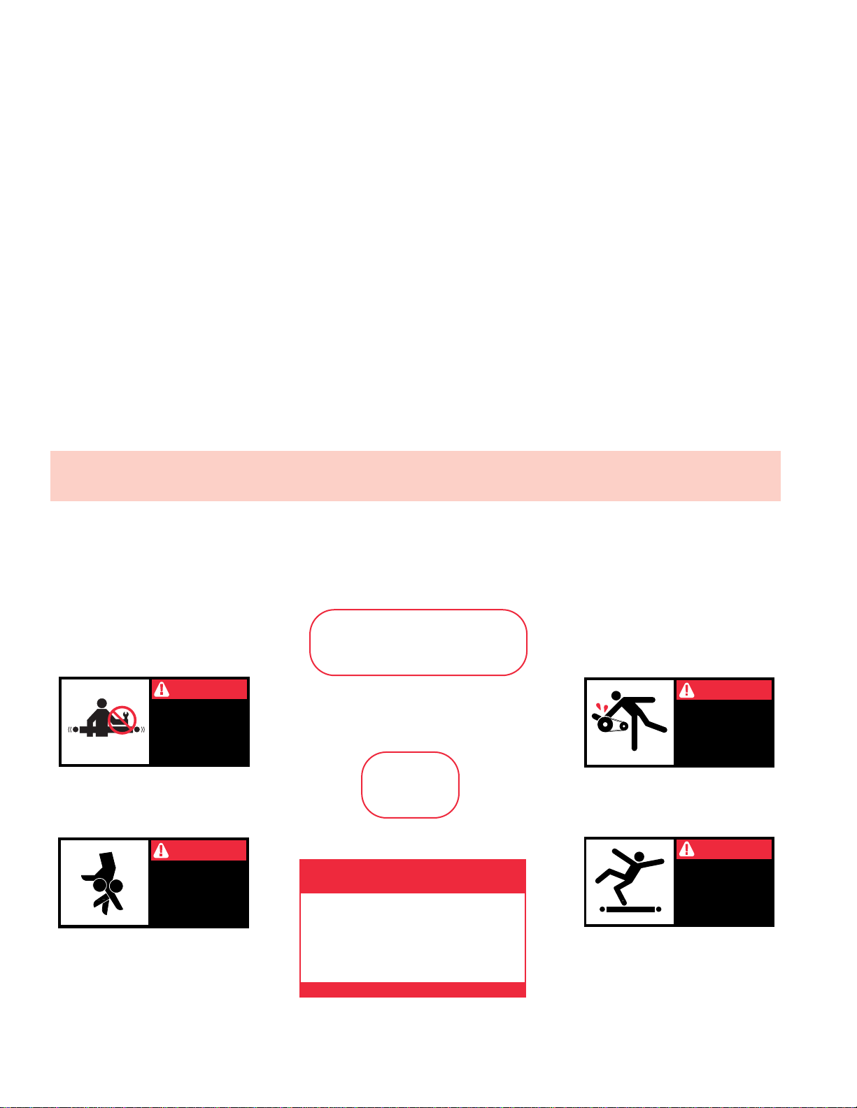
WARNING!
Electrical controls shall be installed and
wired by a qualified electrician. Wiring
information for the motor and controls are
furnished by the equipment manufacturer.
CONTROLS
Electrical Code: All motor controls and wiring shall con-
form to the National Electrical Code (Article 670 or other
applicable articles) as published by the National Fire
Protection Association and as approved by the American
Standards Institute, Inc.
CONTROL STATIONS
A) Control stations should be so arranged and located
that the operation of the equipment is visible from them,
and shall be clearly marked or labeled to indicate the
function controlled.
B) A conveyor which would cause injury when started
shall not be started until employees in the area are alert-
ed by a signal or by a designated person that the con-
veyor is about to start.
When a conveyor would cause injury when started
and is automatically controlled or must be controlled from
a remote location, an audible device shall be provided
which can be clearly heard at all points along the con-
veyor where personnel may be present. The warning
device shall be actuated by the controller device starting
the conveyor and shall continue for a required period of
time before the conveyor starts. A flashing light or similar
visual warning may be used in conjunction with or in
place of the audible device if more effective in particular
circumstances.
Where system function would be seriously hindered
or adversely affected by the required time delay or where
the intent of the warning may be misinterpreted (i.e., a
work area with many different conveyors and allied
devices), clear, concise, and legible warning shall be pro-
vided. The warning shall indicate that conveyors and
allied equipment may be started at any time, that danger
exists, and that personnel must keep clear. The warnings
shall be provided along the conveyor at areas not guard-
ed by position or location.
C) Remotely and automatically controlled conveyors,
and conveyors where operator stations are not manned
or are beyond voice and visual contact from drive areas,
loading areas, transfer points, and other potentially haz-
ardous locations on the conveyor path not guarded by
location, position, or guards, shall be furnished with
emergency stop buttons, pull cords, limit switches, or
similar emergency stop devices.
All such emergency stop devices shall be easily iden-
tifiable in the immediate vicinity of such locations unless
guarded by location, position, or guards. Where the
design, function, and operation of such conveyor clearly
is not hazardous to personnel, an emergency stop
device is not required.
The emergency stop device shall act directly on the
control of the conveyor concerned and shall not depend
on the stopping of any other equipment. The emergency
stop devices shall be installed so that they cannot be
overridden from other locations.
D) Inactive and unused actuators, controllers, and wiring
should be removed from control stations and panel
boards, together with obsolete diagrams, indicators, con-
trol labels, and other material which serve to confuse the
operator.
SAFETY DEVICES
A) All safety devices, including wiring of electrical safety
devices, shall be arranged to operate in a “Fail-Safe”
manner, that is, if power failure or failure of the device
itself would occur, a hazardous condition must not result.
B)
Emergency Stops and Restarts.
Conveyor controls
shall be so arranged that, in case of emergency stop,
manual reset or start at the location where the emer-
gency stop was initiated, shall be required of the con-
veyor(s) and associated equipment to resume operation.
C) Before restarting a conveyor which has been stopped
because of an emergency, an inspection of the conveyor
shall be made and the cause of the stoppage deter-
mined. The starting device shall be locked out before any
attempt is made to remove the cause of stoppage,
unless operation is necessary to determine the cause or
to safely remove the stoppage.
Refer to ANSI Z244.1-1982, American National Standard
for Personnel Protection – Lockout/Tagout of Energy
Sources – Minimum Safety Requirements and OSHA
Standard Number 29 CFR 1910.147 “The Control of
Hazardous Energy (Lockout/Tagout).”
"Building Relationships One Conveyor Part at a Time"

9
OPERATION
● Operation Safety Precautions
A) Only trained employees shall be permitted to operate
conveyors. Training shall include instruction in operation
under normal conditions and emergency situations.
B) Where employee safety is dependent upon stopping
and/or starting devices, they shall be kept free of
obstructions to permit ready access.
C) The area around loading and unloading points shall
be kept clear of obstructions which could endanger per-
sonnel.
D) No person shall ride the load-carrying element of a
conveyor under any circumstances unless that person is
specifically authorized by the owner or employer to do
so. Under those circumstances, such employee shall
only ride a conveyor which incorporates within its sup-
porting structure, platforms or control stations specifical-
ly designed for carrying personnel. Under no circum-
stances shall any person ride on any element of a verti-
cal conveyor. Owners of conveyors should affix warning
devices to the conveyor reading Do Not Ride Conveyor.
E) Personnel working on or near a conveyor shall be
instructed as to the location and operation of pertinent
stopping devices.
F) A conveyor shall be used to transport only material it
is capable of handling safely.
G) Under no circumstances shall the safety characteris-
tics of the conveyor be altered if such alterations would
endanger personnel.
H) Routine inspections and preventive and corrective
maintenance programs shall be conducted to insure that
all safety features and devices are retained and function
properly.
I) Personnel should be alerted to the potential hazard of
entanglement in conveyors caused by items such as
long hair, loose clothing, and jewelry.
J) As a general rule, conveyors should not be cleaned
while in operation. Where proper cleaning requires the
conveyor to be in motion and a hazard exists, personnel
should be made aware of the associated hazard.
● Conveyor Start-Up
CAUTION!
Because of the many moving parts on the
conveyor, all personnel in the area of the
conveyor need to be warned that the con-
veyor is about to be started.
Before conveyor is turned on, check for foreign objects
that may have been left inside conveyor during installa-
tion. These objects could cause serious damage during
start-up.
After conveyor has been turned on and is operating,
check motors, reducers, and moving parts to make sure
they are working freely.
"Building Relationships One Conveyor Part at a Time"
Use code HYPMANUAL for free shipping
on your first order at HytrolParts.com

10
● Belt Tracking
HOW THE CONVEYOR BELT IS TRACKED
The belt is tracked by adjusting: Drive Pulley, Tail Pulley,
Return Idlers, and Snub Idlers. The same tracking principles
apply to conveyors supplied with end drives, center drives, or
underside take-ups.
PRE-TRACKING INSPECTION
Before attempting to physically track the belt:
Make sure conveyor is level across the width and
length of unit. Adjust supports as necessary.
Check to make sure: Drive Pulley, Tail Pulley, Snub
Idlers, and all Return Idlers are square with conveyor
bed. See illustration 10A, 10B, and 10C. Dimension “A”
should be equal on both sides of unit.
Make sure belt has been properly threaded through
conveyor. See “Belt Installation”, Page 7.
Check for improper loading. Feed should be in direction
of belt travel, centered on belt.
Make sure belt lacing has been installed correctly and
is square with the belt.
1. . .
2. . .
3. . .
4. . .
5. . .
FIGURE 10A SQUARING 14” END DRIVE
FIGURE 10B SQUARING RETURN IDLER
DRIVE PULLEY
SNUB
IDLER
ADJUSTABLE IDLER
BRACKET
ADJUSTMENT
SCREW
RETURN BELT
RETURN IDLER
ADJUSTMENT BOLTS
ADJUSTABLE IDLER
BRACKET
FIGURE 10C SQUARING TAIL PULLEY
ADJUSTMENT BOLT
SNUB IDLER
ADJUSTABLE
IDLER
BRACKET
“A”
TAKE-UP
BOLT
TAIL
PULLEY
"Building Relationships One Conveyor Part at a Time"
Use code HYPMANUAL for free shipping
on your first order at HytrolParts.com

11
● Belt Tracking
(Continued)
CAUTION!
Only trained personnel should track convey-
or belt which must be done while conveyor
is in operation.
IMPORTANT: When belt tracking adjustments are made,
they should be minor (1/16 in. at a time on idlers, etc., should
be sufficient.).
Give the belt adequate time to react to the adjustments. It may
take several complete revolutions around the conveyor for the
belt to begin tracking properly on long, slow conveyor lines.
A) Stand at tail pulley looking toward drive and note what
direction belt is traveling.
B) Having observed belt and determined tracking problem, fol-
low procedures in “How to Steer The Belt”, See Figure 11A.
FLOW
SIDE "X"
TAIL PULLEY TAIL PULLEY
BELT SNUB IDLER
INFEED
DISCHARGE
SIDE "Y"
FIGURE 11A
HOW TO STEER THE BELT
Condition 1. . .When the belt is running in the direction
(FLOW) with the arrow, but tracking (drifting) towards Side “X”,
move the Snub Idler nearest the INFEED end of Side “Y”
towards the DISCHARGE end of the conveyor.
Condition 2. . . When the belt is running in the direction
(FLOW) with the arrow, but tracking (drifting) towards Side “Y”,
move the Snub Idler nearest the INFEED end of Side “X”
towards the DISCHARGE end of the conveyor.
If Belt Direction (FLOW) is reversed, all the above conditions
will remain the same as in Figure 11A,
except you are now
viewing the conveyor from the opposite end.
If belt continues to track improperly, re-check all items covered
in “Pre-Tracking Inspection” and make corrections as neces-
sary.
NOTE: In all conditions, you are viewing
the Conveyor Belt from the INFEED end.
All corrections will be made from the
INFEED end of conveyor.
"Building Relationships One Conveyor Part at a Time"
Use code HYPMANUAL for free shipping
on your first order at HytrolParts.com

12
MAINTENANCE
● Maintenance Safety Precautions
A) Maintenance, such as lubrication and adjustments, shall
be performed only by qualified and trained personnel.
B) It is Important that a maintenance program be established
to insure that all conveyor components are maintained in a
condition which does not constitute a hazard to personnel.
C) When a conveyor is stopped for maintenance purposes,
starting devices or powered accessories shall be locked or
tagged out in accordance with a formalized procedure
designed to protect all person or groups involved with the con-
veyor against an unexpected start.
D) Replace all safety devices and guards before starting
equipment for normal operation.
E) Whenever practical, DO NOT lubricate conveyors while
they are in motion. Only trained personnel who are aware of
the hazard of the conveyor in motion shall be allowed to lubri-
cate.
SAFETY GUARDS
Maintain all guards and safety devices IN POSITION and IN
SAFE REPAIR.
WARNING SIGNS
Maintain all warning signs in a legible condition and obey all
warnings. See Page 2 of this manual for examples of warning
signs.
● Lubrication
BEARINGS
STANDARD: Supplied sealed and pre-lubricated. No
lubrication required.
CHAIN
It is recommended that the drive chain be lubricated with
SAE-30 oil approximately every 40 hours of operation.
Under extreme conditions, more frequent lubrication may
be required. (Also, See “Drive Chain Alignment and
Tension”.).
REDUCERS
MANUFACTURED BY HYTROL: See separate manual
in Packing Envelope that contains lubrication and main-
tenance instructions for HYTROL’s Gear Reducer.
MANUFACTURED BY OTHERS: Refer to their recom-
mendations.
"Building Relationships One Conveyor Part at a Time"
Use code HYPMANUAL for free shipping
on your first order at HytrolParts.com

13
● Drive Chain Alignment and Tension
CAUTION!
Never remove chain guards while the con-
veyor is running. Always replace guards
after adjustments are made.
The drive chain and sprockets should be checked peri-
odically for proper tension and alignment. Improper
adjustment will cause extensive wear to the drive com-
ponents.
Remove chain guard.
Check sprocket alignment by placing a straightedge
across the face of both sprockets. (Figure 13A.) Loosen
set screws and adjust as needed. Re-tighten set
screws.
To adjust chain tension, loosen bolts that fasten motor
base to mounting angles, both sides of conveyor.
Tighten take-up bolts until desired chain tension is
reached. (Figures 13B & 13C). Re-tighten mounting
bolts.
Make sure both sides are adjusted the same amount to
prevent mis-alignment of sprockets. Re-tighten mount-
ing bolts.
Lubricate chain per lubrication instructions.
Replace chain guard so that it does not interfere with
drive.
TO MAKE ADJUSTMENTS
1. . .
2. . .
3. . .
4. . .
5. . .
6. . .
FIGURE 13A
DRIVE
SHAFT
SPROCKET
STRAIGHT EDGE
FIGURE 13B
FIGURE 13C
MOUNTING
BOLTS
TAKE-UP BOLTS
REDUCER SPROCKET
MOTOR/REDUCER DRIVE
DRIVE PULLEY
SPROCKET
DRIVE PULLEY
MOTOR BASE PLATE
SET
SCREWS
GEAR
REDUCER
REDUCER
SPROCKET
SPROCKET
CENTERS
APPROX. 1/4” OR 2% OF
SPROCKET CENTERS
CHAIN TOO TIGHT
(REQUIRES EXTRA POWER) CHAIN TOO LOOSE
CORRECT SLACK
"Building Relationships One Conveyor Part at a Time"
Use code HYPMANUAL for free shipping
on your first order at HytrolParts.com

14
● Trouble Shooting
The following charts list possible problems that may
occur in the operation of a powered conveyor.
TROUBLE SHOOTING DRIVES
TROUBLE CAUSE SOLUTION
Conveyor will not start or motor quits fre-
quently.
Drive chain and sprockets wear excessively.
Loud popping or grinding noise.
Motor or reducer overheating.
Belt doesn’t move, but drive runs.
1) Motor is overloaded or drawing too much
current.
1) Lack of lubrication on chain causing chain
stretch which creates improper chain to
sprocket mesh.
2) Sprockets are out of alignment.
3) Loose chain.
1) Defective bearing.
2) Loose set screws in bearing.
3) Loose drive chain.
1) Conveyor is overloaded.
2) Low voltage to motor.
3) Low lubricant level in reducer.
1) Conveyor is overloaded.
2) Belt is too loose.
3) Lagging on drive pulley is worn.
1) Check for overloading of conveyor.
2) Check heater or circuit breaker and change if necessary.
1) Replace chain and sprockets. Provide adequate lubrication.
NOTE: If problem reoccurs, a chain take-up may be required.
2) Align sprockets. See “Drive Chain Alignment and Tension” in this
manual.
3) Tighten chain.
1) Replace bearing.
2) Tighten set screw.
3) Tighten chain.
1) Check capacity of conveyor and reduce load to recommended
level.
2) Have electrician check and correct as necessary.
3) Relubricate per manufacturer’s recommendations. For HYTROL
reducer, refer to separate manual.
1) Reduce load.
2) Use belt take-up to tighten belt.
3) Replace drive pulley lagging and tighten belt.
TROUBLE SHOOTING DRIVE BELT TRACKING
TROUBLE CAUSE SOLUTION
Entire length of belt creeps off at one spot
only.
Entire belt creeps to one side at tail pulley.
Entire belt creeps to one side.
1) One or more idlers (usually near trouble
spot) are out of line.
2) One conveyor section not level or square.
3) Material build-up on pulleys or idlers.
1) Tail Pulley, Return Idler, or Snub Idler near
Tail Pulley not properly aligned or square
with bed.
1) Conveyor not straight.
2) Conveyor not level.
3) Material build-up on rollers, pulleys, or
idlers.
1) Adjust as necessary. See “Belt Tracking Pre-Tracking
Inspection” in this manual for details.
2) Make necessary adjustments to supports.
3) Remove residue from pulleys or idlers. Install belt cleaners or
scrapers if possible.
1) Adjust as necessary. See “Belt Tracking, Pre-Tracking
Inspection” in this manual on how to square Tail Pulley, Snub
Idler, and Return Idler.
1) Re-align bed sections as necessary.
2) Correct as necessary.
3) Remove residue and install belt cleaners or scrapers, if
possible.
"Building Relationships One Conveyor Part at a Time"
Use code HYPMANUAL for free shipping
on your first order at HytrolParts.com

15
● Preventive Maintenance Checklist
● How to Order Replacement Parts
The following is a general maintenance checklist which
covers the major components of your conveyor.
This will be helpful in establishing a standard mainte-
nance schedule.
Included in this manual are parts drawings with complete
replacement parts lists. Minor fasteners, such as nuts
and bolts, are not included.
When ordering replacement parts:
Contact Dealer from whom conveyor was purchased or
nearest HYTROL Distributor.
Give Conveyor Model Number and Serial Number or
HYTROL Factory Order Number.
Give Part Number and complete description from Parts
List.
If you are in a breakdown situation, tell us.
Hytrol Conveyor
Company, Inc.
JONESBORO, ARKANSAS ST. LOUIS, MISSOURI
MANTECA, CALIFORNIA
Model
C
SERIAL # 775544
HYTROL Serial Number
(Located near Drive
on Powered Models)
1. . .
2. . .
3. . .
4. . .
Check Noise
Check Temperature
Check Mounting Bolts
Check Noise
Check Temperature
Check Oil Level
Check Tracking
Check Tension
Check Lacing
Check Tension
Lubricate
Check for Wear
Check Tension
Check for Wear
Check for Sheave Alignment
General Check: All loose bolts, etc.,
tightened
Check Noise
Check Mounting Bolts
Check for Wear
Check Set Screws & Keys
SCHEDULE
SUGGESTED ACTIONCOMPONENT
MOTOR
REDUCER
BELT
DRIVE CHAIN
STRUCTURAL
V-BELTS
BEARINGS
(Pulleys & Rollers)
SPROCKETS
Weekly Monthly Quarterly
"Building Relationships One Conveyor Part at a Time"
Use code HYPMANUAL for free shipping
on your first order at HytrolParts.com

16
● Model C Parts Drawing
44
46 49
50
47 48
39 37 54 55 56 12
60
36
595857
41
39
37
38
40
41
45
43
51
62
53
42 35
34 52
32 33
61
60
36
66
67
68
65
64
64
63
39
37
41
38
63
64
65
66
67
37
43
42
62
62
35
34
52
47 48 4950
39
40
38
59
58
57
45
60
61 12
35
32 33
34
62
13
17
16
1
36
2
31
23 25
27
28
29
11
10
30
24
1
16
26
36
3
5
48
6917 210 11 18 19 20 21 22
33
15
34
12
7
14
32
60
9
8
"Building Relationships One Conveyor Part at a Time"
Use code HYPMANUAL for free shipping
on your first order at HytrolParts.com

Ref. No. Part No. Description
32 B-06223 RH Gravity Bracket—Drive End
33 B-06238 LH Gravity Bracket—Drive End
34 B-02912 1 in. Dia. Pop-Out Roller (Specify OAW)
35 B-02624 Gravity Bar (Specify OAW)
36 — Drive Bed Assembly
— B-00183 6 ft. Long (Specify OAW)
— B-00185 8 ft. Long (Specify OAW)
— B-002136 10 ft. Long (Specify OAW)
37 — Intermediate and Tail Bed Assembly
— B-01254 6 ft. Long 20 in. OAW
— B-01257 6 ft. Long 24 in. & 30 in. OAW (Specify)
— B-01255 8 ft. Long 20 in. OAW
— B-01258 8 ft. Long 24 in. & 30 in. OAW (Specify)
— B-01256 10 ft. Long 20 in. OAW
— B-02302 10 ft. Long 24 in. & 30 in. OAW (Specify)
38 B-00163 Splice Plate
39 B-01884 Bed Spacer (Specify OAW)
40 093.215 Return Roller Bracket
41 — Spooled Idler Assembly
— B-05587 20 in. & 24 in. OAW (Specify)
— B-05585 30 in. OAW (Specify)
42 B-22221 4 in. Dia. Tail Pulley—20 in., 24 in. & 30 in. OAW (Specify)
43 B-21349-R Take-up Plate Assembly—RH
44 B-21349-L Take-up Plate Assembly—LH
45 B-21347-R Adjustment Plate Assembly—RH
46 B-21347-L Adjustment Plate Assembly—LH
47 041.919 Acorn Nut, 3/8-16
48 042.919 Shoulder Bolt, 1/2 in. Dia. x .312 Long
49 040.4065 Take-up Screw, 1/2-13 x 4 in. Long
50 041.201 Hex Jam Nut, 1/2-13
51 010.102 3-Bolt Flange Bearing, 1 in. Bore
52 B-09859 Nip Point Guard (Specify OAW)
53 B-02632 Gravity Bracket (Tail End)
54 —
Belt—Black Trackmate 447 Roughtop w/ PVC Cover (Specify Width)
55 — U3 Clipper Unibar Lacing (Specify Length)
56 — #13 Lacing Pin
57 099.105 Cleat—1-1/2 in. Dia. Wood
58 042.401 Elevator Bolt—5/16-18
59 041.101 Hex Nut, 5/16-18
60 B-00193 C-22 Support Frame—Drive End (Specify OAW)
61 B-00372 Adjustable Leg, C-22 Support
62 091.110 Cable Assembly
63 — Undertrussing (See Page 18 & 19)
64 — MS Type Pivot Plate—1-1/2 in. Flange
— B-00913 3-11/16 in. High
— B-02112 1-9/16 in. High
65 — Floor Support Frame
— B-00914 6 in. High (Specify OAW)
— B-12777 7 in. High (Specify OAW)
— B-12778 8 in. High (Specify OAW)
— B-00915 9 in. High (Specify OAW)
— B-00916 11-1/2 in. High (Specify OAW)
— B-00917 14-1/2 in. High (Specify OAW)
— B-02098 18-1/2 in. High (Specify OAW)
— B-00919 22-1/2 in. High (Specify OAW)
— B-00921 32-1/2 in. High (Specify OAW)
— B-00923 44-1/2 in. High (Specify OAW)
— B-00925 56-1/2 in. High (Specify OAW)
— B-02107 68-1/2 in. High (Specify OAW)
— B-02109 78-1/2 in. High (Specify OAW)
— B-02111 90-1/2 in. High (Specify OAW)
66 B-00911 Adjustable Foot Assembly (Specify Length)
67 — Knee Brace
— B-00303 36 in. Long
— B-00705 27 in. Long
68 B-01717 Knee Brace Bracket
69 B-06036 Support Splice Channel (Not Shown)
Ref. No. Part No. Description
1 — Motor—Foot Mounted
— 030.3044 3/4 HP—230/460 VAC—3 Ph.—60 Hz.—TEFC
— 030.4044 1 HP—230/460 VAC—3 Ph.—60 Hz.—TEFC
— 030.5034 1-1/2 HP—230/460 VAC—3 Ph.—60 Hz.—TEFC
— 030.6034 2 HP—230/460 VAC—3 Ph.—60 Hz.—TEFC
2 — Speed Reducer
—
R-00152-020R
4A—RH—20:1 Ratio
—
R-00163-020R
5A—RH—20:1 Ratio
3 — Sheave—Motor, 2.25 in. Dia.
— 020.101 Single Groove—5/8 in. Bore—3/4 HP
— 021.101 Double Groove—5/8 in. Bore—1 HP
— 021.110 Double Groove—7/8 in. Bore—1-1/2 & 2 HP
4 — Sheave—Reducer, 5.45 in. Dia.
— 020.121 Single Groove—3/4 in. Bore—3/4 HP
— 021.108 Double Groove—3/4 in. Bore—1 thru 2 HP
5 — V-Belt
— 066.105 4L270 (3/4—1 HP)
— 066.109 4L310 (1-1/2—2 HP)
6 — Sprocket—Reducer
— 028.134 50B16 x 1 in. Bore (4A)
— 028.1342 50B16 x 1-1/4 in. Bore (5A)
7 — Sprocket—Drive Pulley
— 027.100 50A30 x 1 in. Bore
— 027.102 50A30 x 1-1/4 in. Bore
8 090.202 Shaft Key—3/16 in. Sq. x 1 in. Long
9 090.203 Shaft Key—1/4 in. Sq. x 1 in. Long
10 029.101 #50 Riveted Roller Chain
11 029.201 Connector Link—#50 Roller Chain
12 B-00415 14” Dia. Dr. Pulley (Fully Lagged) (Specify OAW)
13 — Drive Shaft (Specify)
— B-00019 20 in. OAW
— B-00421 24 in. OAW
— B-00422 30 in. OAW
14 — Spacer—Drive Shaft (Long) (Specify)
— 098.156 1 in. I.D. x 1-15/16 in. Long (20 in. OAW)
— B-00424 1-1/4 in. I.D. x 1-15/16 in. Long (24 in. & 30 in. OAW)
15 — Spacer—Drive Shaft (Short) (Specify)
— 098.155 1 in. I.D. x 11/16 in. Long (20 in. OAW)
— B-00425 1-1/4 in. I.D. x 11/16 in. Long (24 in & 30 in. OAW)
16 B-00133 Drive Plate Assembly—RH
17 B-00134 Drive Plate Assembly—LH
18 12.101 Roller Brg.—1 in I.D. x 1-1/2 in. Long with Split Race
19 B-00015 Bearing Retainer
20 093.107 Spring Clip—Bearing Retainer
21 092.103 Grease Fitting—1/8 NPT
22 049.3053 External Retaining Ring
23 B-04842 11/16 in. Hex Idler Bracket
24 G-00472 25 Roller Assembly (Specify Between Brackets)
25 B-00662 Drive Idler Bracket—RH
26 B-00663 Drive Idler Bracket—LH
27 — Motor Base Assembly
— B-10987 20 in. thru 30 in. OAW (4A) (Specify)
— B-10988 24 in. thru 30 in. OAW (5A) (Specify)
28 040.307 Take-up Bolt—3/8-16 x 2-1/4 in. Long
29 041.300 Hex Jam Nut—Heavy—3/8-16
30 — V-Belt Guard—Inside (Specify)
— B-05275 3/4 & 1 HP—20 in. thru 30 in. OAW
— B-05275 1-1/2 & 2 HP—20 in. OAW
— B-05120 1-1/2 & 2 HP—24 in. thru 30 in. OAW
31 — V-Belt Guard—Outside (Specify)
— B-05274 3/4 & 1 HP—20 in. thru 30 in. OAW
— B-05274 1-1/2 & 2 HP—20 in. OAW
— B-05119 1-1/2 & 2 HP—24 in. thru 30 in. OAW
See Page 15 For Information On
How To Order Replacement Parts Recommended Spare Parts List Highlighted in Gray
17
● Model C Parts List
"Building Relationships One Conveyor Part at a Time"
Use code HYPMANUAL for free shipping
on your first order at HytrolParts.com

18
● Undertrussing - Model C
BED LENGTH INFEED END
6' 10' 6'
22'
BB
10-1/2" 10-1/2"
177"
10-1/2" 34-1/2"
24'
BB
6' 10'
177"
8'
10-1/2" 34-1/2"
28'
BCB
10'10'
148"76"
8'
10-1/2" 10-1/2"
30'
BCB
10'10'
119"76" 76"
10'
C
34-1/2" 34-1/2"
26'
BB
8' 10'
177"
8'
20' A
10' 10'
C
"X"
"X"
15-5/8"
D
D
2" 6-5/8" BED
5"
2"
5"
"Building Relationships One Conveyor Part at a Time"

19
● Undertrussing - Model C
Ref.
No. Part
No. Description
A
B
C
D
E
B-13138
B-12639
B-12640
B-12641
B-963
Joint Support (20 ft. Bed Length, FJ, C Only)
Truss Rod End Bracket
Truss Rod Center Bracket
Truss Rod (Specify Length)
Cross Brace (Specify OAW)
32'
BB
6'
10-1/2" 10-1/2"
10' 10'
148" 148"
6'
10-1/2" 34-1/2"
34'
BB
6' 10' 10'
148" 148"
8'
10-1/2" 10-1/2"
38'
BCC B
10' 10'10'
119" 119" 52"76"
8'
C
10-1/2" 10-1/2"
40'
BCB
10'10'
119" 119"76" 76"
10'10'
CC
10-1/2" 10-1/2"
36'
BCC
B
8' 10' 10'
119"52" 119" 52"
8'
C
C
C
BED LENGTH INFEED END
12-5/8" A
B
15-5/8"
75"
75"
"Building Relationships One Conveyor Part at a Time"
Use code HYPMANUAL for free shipping
on your first order at HytrolParts.com

20
● Model C Powered Feeder
Parts Drawing
27 30
31 29 36
37 2418 12 630 31
22
20
3
19
21
23
7
13
16
15
14
12
17
40
39
38
43
42
41
28
24
23
31
3026
6
32
33
34
32
5
824
21
25
36 37
3938
40
43
42
41
36 37
5
34
33
32
35
626
23
24
44 1 2 49
10
11
12 319 2324
45
46
"Building Relationships One Conveyor Part at a Time"
Use code HYPMANUAL for free shipping
on your first order at HytrolParts.com
Table of contents
Other HYTROL Industrial Equipment manuals