Linn-High-Therm HT-1500-GT-VAC Special GRAPHITE User manual

O p e r a t i n g I n s t r u c t i o n
High Temperature Furnace
HT-1500-GT-VAC
Special
with options
gas purging, graphite insulation, graphite heating elements,
gas recooling unit with HEPA-filter, second door with fan,
Eurotherm controller, Eurotherm recorder
and
vacuum pump stand
Serial-No. 10025533
EDV-Nr. 19332
L I N N - HIGH- T H E R M G M B H
Heinrich-Hertz-Platz 1 D-92275 Hirschbach Tel. 09665/9140-0 Fax 09665/1720
e-mail: info@Linn.de Internet: www.Linn.de
issue 30.10.2018
M:\1) Widerstand\Faser3 (FKH, FT, HT, VHT, FBV, GBV)\Sonder HT\Sonder HT-1500\HT-1500-GT-VAC-
Special_Graphit_Corning\HT-1500-GT-VAC-Special_Graphit_Corning-e.doc
Linn High Therm GmbH HT-1500-GT-VAC-Spezial GRAPHITE page 2
operating instruction issue 30.10.2018
_____________________________________________________________________________________________________

Linn High Therm GmbH HT-1500-GT-VAC-Spezial GRAPHITE page 3
operating instruction issue 30.10.2018
_____________________________________________________________________________________________________
Original operation manual
Herewith we declare, that the machine
in the delivered design complies with the following provisions:
EC-guide line for machines 2006/42/EC and following, annex I
EC-guide line for EMC 2014/30/EC and following
Following harmonized standards are used particularly:
EN 746 –Industrial thermo-processing units, part 1, part 3
EN 60 204-1 * EN 60 519-1
ISO 12100-1 * ISO 12100-2
EN 55 011 * EN 61 000-6-2

Linn High Therm GmbH HT-1500-GT-VAC-Spezial GRAPHITE page 4
operating instruction issue 30.10.2018
_____________________________________________________________________________________________________
Contents
1. Safety 6
1.1 Designated application................................................................................6
1.2 Explanation of symbols ...............................................................................7
1.3 General advice for safe operation...............................................................8
1.4 Particular dangers.......................................................................................9
1.5 Packing .....................................................................................................10
1.6 Transportation...........................................................................................10
1.7 Storage......................................................................................................10
2. Installation 11
2.1 Place of installation...................................................................................11
2.2 Electrician’s preliminary work on customer’s responsibility .......................11
2.3 Preliminary work on customer’s responsibility for water installation ..........12
2.4 Mounting of heating elements by customer‘s electrician ...........................13
2.5. Electrical connections ...............................................................................15
3. Technical Data 17
4. Description of system 18
4.1 Furnace housing .......................................................................................18
4.2 Insulation...................................................................................................18
4.3 Furnace prepared for the lead –in off three extrusion die ........................18
4.4 Oxygen measurement in the exhaust gas line ..........................................19
4.5 Three zone heating...................................................................................19
4.6 Maximum admissible element temperatures and vacuum ........................19
4.7 Over temperature switch-off......................................................................20
4.8 Thermocouples .........................................................................................20
4.9 Thermocouple safeguard..........................................................................20
4.10 Gas feeding device suitable for vacuum .................................................21
4.11 Additional nitrogen fumigation..................................................................21
4.12 Two additional connections (1/4”) ............................................................21
4.13 Vacuum pump stand system for end pressure.........................................21
4.14 Gas cooling unit ......................................................................................21
4.13 Cooling water control and emergency water cooling...............................22
4.14 Control System........................................................................................23
5. Instructions for temperature controller 24
6. Operating the system 25
6.1 Advice .......................................................................................................25
6.1.1 General Advice..........................................................................................................25
6.1.2 Advice for operating with protective gas .............................................................26
6.1.3 Advice for loading......................................................................................................26

Linn High Therm GmbH HT-1500-GT-VAC-Spezial GRAPHITE page 5
operating instruction issue 30.10.2018
_____________________________________________________________________________________________________
6.2 First start-up..............................................................................................27
6.3 Manual operation ......................................................................................28
6.3 Operation with gas feeding........................................................................28
6.4 Operation under O2atmosphere.............................................................29
6.5 Vacuum operation.....................................................................................29
7. Dew point diagram 30
8. Maintenance 31
9. Spare parts and consumables 32
10. Gas and water flow scheme 33
10.1 Gas flow scheme.....................................................................................33
10.2 Water flow scheme .................................................................................34

Linn High Therm GmbH HT-1500-GT-VAC-Spezial GRAPHITE page 6
operating instruction issue 30.10.2018
_____________________________________________________________________________________________________
1. Safety
IMPORTANT ! Please read manual before installation and start up of system.
In addition to the following items the general safety instructions and accident
prevention regulations are applicable.
Any person who attends system in installation, start-up, operation and maintenance
(inspection, servicing, repair works) must have read and comprehended the whole
operating manual, particularly the safety section. It is recommended that the
proprietor obtains a written acknowledgement by the staff.
Please pass on the safety advices to other users.
1.1 Designated application
The furnace was designed for heat treatments of various materials.
Flammable or explosive materials or those, which release flammable or explosive
substances during the heat-treatment are only allowed to be heated under inert-gas
or reducing atmosphere in this furnace.
It is not permitted to use materials which release as much oxygen at their
decomposition that an explosive gas- or material mixing like explosives etc. is
generated in the furnace.
The manufacturer cannot consider to list all possible applications.
The user is obliged to check and evaluate the effects of heat treatment to each
material and the risks of possible reactions, to avoid injuries and damages.
Any exceeding operation is considered to be not to be designated. Manufacturer will
not warrant for damages resulting therefrom; the risk is fully on the user.

Linn High Therm GmbH HT-1500-GT-VAC-Spezial GRAPHITE page 7
operating instruction issue 30.10.2018
_____________________________________________________________________________________________________
1.2 Explanation of symbols
This sign directs to important safety instructions.
Disregarding may lead to endanger your personal safety and/or
other’s properties.
Read and observe all instructions in this operation manual.
This sign directs to important safety instructions.
Disregarding may lead to endanger system’s safety
and/or other’s properties.
Read and observe all instructions in this operation manual.

Linn High Therm GmbH HT-1500-GT-VAC-Spezial GRAPHITE page 8
operating instruction issue 30.10.2018
_____________________________________________________________________________________________________
1.3 General advice for safe operation
I) Limitations of application are listed in the corresponding sections of this
manual and the relevant directives must be considered and followed.
When dealing with gases it has to be followed to the corresponding safety
regulations. (UVV gases, ex guideline…)
The manufacturer cannot consider to list all possible applications.
The user is obliged to check and evaluate the effects of heat treatment to
each material and the risks of possible reactions, to avoid injuries and
damages.
Any exceeding operation is considered to be not to be designated.
Manufacturer will not warrant for damages resulting therefore; the risk is fully
on the user.
II) Any mode of operation must be avoided, which might reduce the system’s
safety.
Occuring changes at the system, which reduce safety must be immediately
reported, documented and repaired.
The local safety and accident prevention regulations are applicable.
Where necessary, operating staff is obliged to wear protective clothing
(gloves, goggles, etc.).
It is in the proprietor’s responsibility to ensure by appropriate instructions and
controls that the system and working place are kept clean and clear.
Safety devices may not be dismounted or set out of operation.
Switch system off mains before cleaning and repair works, in order to
ensure unauthorized switching on.
III) Subject to modifications by technical progress !

Linn High Therm GmbH HT-1500-GT-VAC-Spezial GRAPHITE page 9
operating instruction issue 30.10.2018
_____________________________________________________________________________________________________
1.4 Particular dangers
Linn heat treatment systems are designed in compliance with the actual technical
status and safe in operation.
However, dangers may come for these heating systems :
I. Risk of unintentional chemical reactions
Material advice 1 :
Flammable or explosive materials or those, which release flammable or
explosive substances during the heat-treatment are not allowed to be heated
in this furnace.
Material advice 2 :
It is not permitted to use materials which release as much oxygen at their
decomposition that an explosive gas- or material mixing like explosives etc. is
generated in the furnace.
II. Risk of burnings
Risk of burnings arises when furnace casing is touched unprotected,
depending on furnace temperature. Proper protections ( gloves ) must be
worn resp. avoid contact of unprotected parts of the body with the furnace
casing.
III. Risk of fire
Do not place inflammable objects ( e.g. office materials ) on the furnace or in
close range.

Linn High Therm GmbH HT-1500-GT-VAC-Spezial GRAPHITE page 10
operating instruction issue 30.10.2018
_____________________________________________________________________________________________________
1.5 Packing
The system is packed for transportation. Packing corresponds with the guidelines for
packings of VDMA and is only intended for transportation. It protects to a limited
extent from humidity, heat and mechanical impacts. Open and remove at place of
installation only.
Packing material must be disposed of properly after use.
1.6 Transportation
Transportation must be performed by specialists, who know and follow the safety
regulations. All advices on packaging and transport documents must be obeyed
during transport. Transportation packaging does not protect the contents against
improper handling !
1.7 Storage
When system has to be stored all safety precautions for transportation will apply.
Additionally the following protections must be provided :
condensed water ( generated by high changes of temperature )
dust
freeze
damage to packaging
vermins ( particularly rats and mice can destroy electric switchings )

Linn High Therm GmbH HT-1500-GT-VAC-Spezial GRAPHITE page 11
operating instruction issue 30.10.2018
_____________________________________________________________________________________________________
2. Installation
2.1 Place of installation
Furnace system should be placed in a clear area, i.e. distance of 100 to 200 mm to
the wall should be considered. The room should be equipped with an exhaust
device, also a properly functioning exhaust hood will be suitable.
The bare heads of thermocouple connectors at the furnace’s rear may not be
exposed to a temperature considerably higher than ambient. E.g. avoid to place a
poor insulated furnace next to the system. When connector heads are becoming too
hot, temperature in muffle will be indicated lower than the actual temperature is. This
can, under extreme conditions, destroy the muffle.
2.2 Electrician’s preliminary work on customer’s responsibility
Works as described below may only by performed by
properly trained personnel.
1. Mounting of a three-pole lever switch, the furnace system must be firmly
connected.
2. Connecting of control system to mains supply according to the attached
circuit diagram.
3. Connecting of furnace casing and pump stand with control system according
to circuit diagram.
4. Connecting of all flexible vacuum tubings between gas –vacuum system,
pumpstand and furnace section.
5. Proper grounding of furnace and control system.

Linn High Therm GmbH HT-1500-GT-VAC-Spezial GRAPHITE page 12
operating instruction issue 30.10.2018
_____________________________________________________________________________________________________
2.3 Preliminary work on customer’s responsibility for water installation
2.3.1 Cooling water supply between the furnace and the cooling unit type Typ
Sigma 18
The cooling water supply occurs through a cooling unit type Typ Sigma 18. For the
fresh water supply of the cooling unit type Typ Sigma 18, an installation of a ¾”
connection with pre-filter is necessary. Between the cooling unit type Typ Sigma 18
and the furnace are laid 1 1/4 ” water pipes for the cooling water run in or rather
cooling water drain.
The connections for the water run in and water drain have to be provided with hose
fittings. The furnace is already cased.
2.3.2 Emergency cooling water supply
The emergency cooling water supply of the furnace occurs over a separate
connection to the main water line mains of the user. The main water circuit will be
activated through special NO - water valves when the power supply system fall out.
At the same time it ensures also the cooling of the furnace. The emergency water
supply or rather the emergency water drain of the furnace occurs over a 1 1/2”
connection.
The emergency water access of the furnace is provided with a shut-off valve with
vane relay. If the shut-off valve do not open during furnace start the program of the
furnace will not start and an alarm will release.
The shut-off valve has to be closed at the end of the furnace program and by cooled
down and switched off furnace that no fresh water flows through the furnace
permanent.
The connections for the water run in and water drain have to be provided with hose
fittings. The furnace is already cased.
Please check the water pressure in your pipe mains before the connection of the
machine. The pressure has to be also in summer min. 3 bar but max. 5 bar. It has
to be used a circulation cooling unit if the water pressure is too low. The water
pipe which leads to the machine has to be provided with pressure reducing valve
if the water pressure is bigger than 5 bar.
The water flow should be min. 35 l/min. If the water flow is too low the silicone
flat seal will be destroyed very fast. A too big water flow has a negative influence
on the temperature distribution in the muffle. Ideal would be a water temperature
in the drain of 25-35°C by a max. furnace temperature. The water has to flow until
the furnace is cooled down to room temperature.
The water drain for the cooling water has to be work without back pressure.
By water supply mains which lead to deposits or incrustations, the installation of
a flow filter would be necessary.

Linn High Therm GmbH HT-1500-GT-VAC-Spezial GRAPHITE page 13
operating instruction issue 30.10.2018
_____________________________________________________________________________________________________
2.4 Mounting of heating elements by customer‘s electrician
Works as described in the following may only be performed by specially
trained personnel
Switch furnace off mains and protect against unauthorized operation.
Heating elements are very sensitive to breakage
Preliminary Works
The cover casing can be unscrewed and taken off.
Looking from top into the furnace casing, the furnace chamber itself with bolted
cover is visible.
Dismantle the water cooling hoses if necessary
Remove furnace chamber cover after unscrewing. Cover of heating chamber
appears. Long holes in the cover are for heating elements. Number of heating
elements depends on the furnace version and varies between four and twelve.
Installation of heating elements
Move the heating element from heating chamber in the holes with the ceramic hull in
the ceiling with the connection ends. Then screw in from above the disc between
graphite connection end and power connecting bolt. Heating element is positioned.
Lift heating element slightly and fill in the gap with graphite fiber.
The next step is to put over the two connecting wires per heating element flank over
the connecting bolt and to fix it. It has to be acted according to connection plan of the
heating elements.
Install remaining heating elements the same way.
Linn High Therm GmbH HT-1500-GT-VAC-Spezial GRAPHITE page 14
operating instruction issue 30.10.2018
_____________________________________________________________________________________________________
GT version
pic. 2.4 Mounting of heating elements GT version
Connect to mains, mounting of connecting clamps
Depending on the version connecting clamps can vary in length and bores. Most
clamps are premounted and are used to connect two heating elements. Also, contact
rails can be included in supply to shunt two heating elements. Pictures explaining
electrical connection are attached to this section.
At first, plastic section which secured for transportation must be unscrewed from the
connecting clamp. Push clamp carefully over the heating element, connecting ends
will take place of plastic section. Position connecting clamps according to the
matching picture and then close screws tightly.
Mount contact rails if indicated.
Mounting is finished after having checked picture for connecting and that all screws
are fitting tightly.
Remaining assembly
Mounting cover of furnace chamber, make sure that silicon sealing remains clean in
furnaces with protective gas operation and that it fits to sealing area between furnace
chamber and it’s cover.
Installation of fanning cover and rear wall of furnace casing same as dismounting in
opposite order.
Linn High Therm GmbH HT-1500-GT-VAC-Spezial GRAPHITE page 15
operating instruction issue 30.10.2018
_____________________________________________________________________________________________________
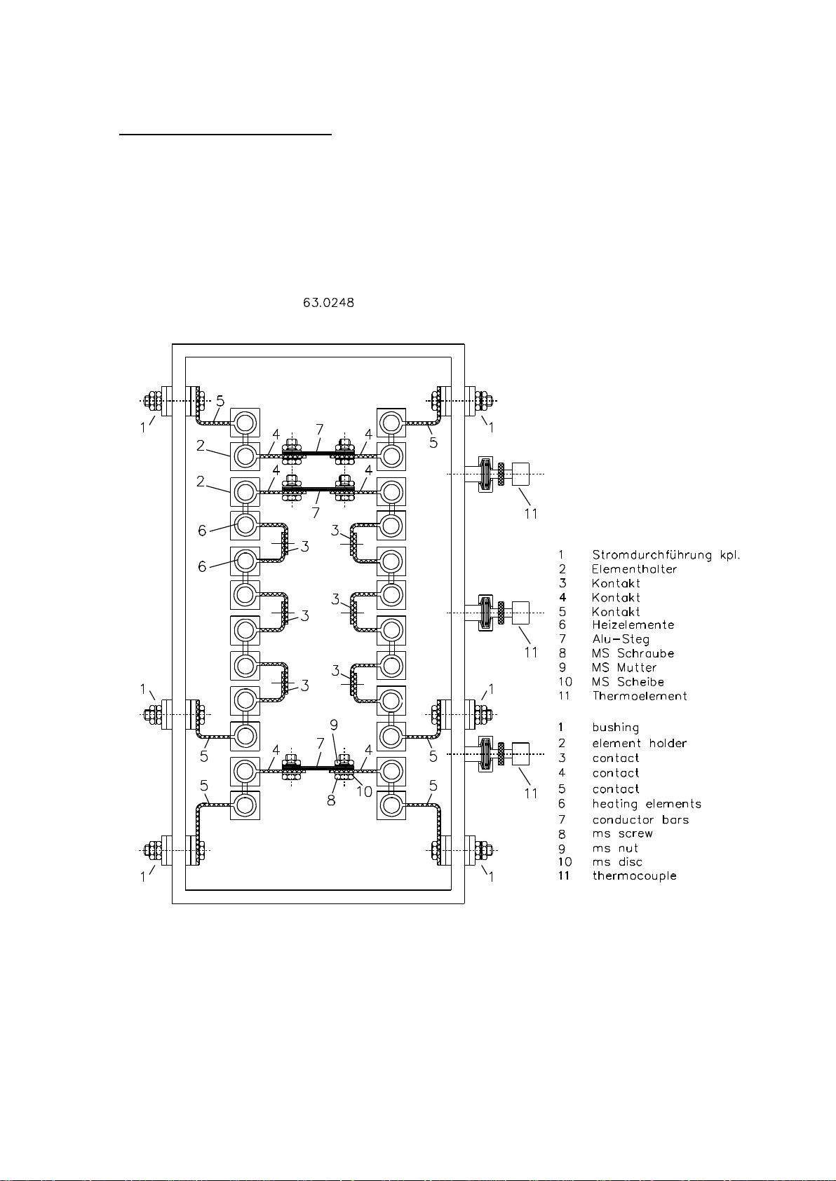
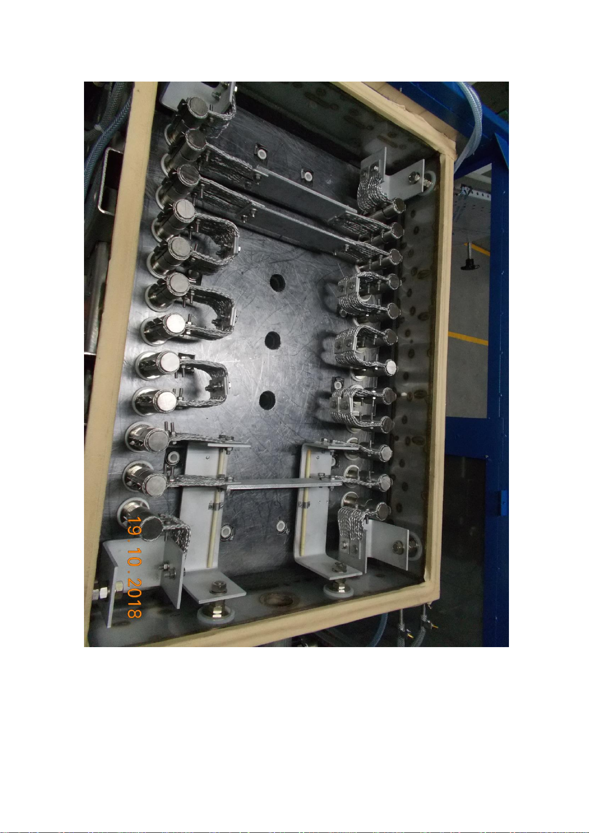
2.5. Electrical connections
Heating elements are connected by configured flat strip laces and rectangular
Aluminium strips. Heating elements are switched with these according to drawing
pic. 2.5 Electrical connection for GT-version (Scheme presentation)
Linn High Therm GmbH HT-1500-GT-VAC-Spezial GRAPHITE page 16
operating instruction issue 30.10.2018
_____________________________________________________________________________________________________
pic. 2.5 Electrical connection for HT-1500-GT-VAC Graphit

Linn High Therm GmbH HT-1500-GT-VAC-Spezial GRAPHITE page 17
operating instruction issue 30.10.2018
_____________________________________________________________________________________________________
3. Technical Data
Electrical connection
Mains: 400 V AC, 3 Ph, N, PE, 50 Hz
Connected power: 140 kVA / 200 A
Dimensions
useful chamber in mm (wxdxh): 430 x 680 x 450
useful volume (liter): 131
outer dimensions furnace in mm (wxdxh): 1200 x 2000 x 2350
outer dimensions with re-cooling unit:
in mm (wxdxh): 2300 x 2400 x 2650
outer dimensions of control unit:
in mm (wxdxh): 1200 x 600 x 2200
outer dimensions of cooling water recooler:
in mm (wxdxh): 730 x 730 x 1600
Temperatures
max. temperature in neutral atmosphere
(short time): 1500 °C
continuous temperature
in neutral atmosphere: 1500 °C
max. temperature in neutral atmosphere
with recirculation fan (short time): 750 °C
relative temperature uniformity: approx. ± 10°C and better in the
middle depending of the load and
the optimization of the control unit
Vacuum
max. Vacuum < 1 mbar

Linn High Therm GmbH HT-1500-GT-VAC-Spezial GRAPHITE page 18
operating instruction issue 30.10.2018
_____________________________________________________________________________________________________
4. Description of system
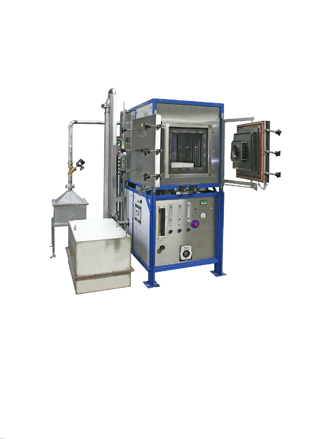
4.1 Furnace housing
The proper furnace housing is made of stainless steel and is provided in touchproof
condition in the outside housing. It is cooled by a fan (plugged sideways on the
bottom on a separately stored housing) so that also during continuous operation a
wall temperature of 180°C is not exceeded. Because of changed position of the fans
the cover will additionally be designed watercooled. The correspondingly designed
outer housing remains relatively cold (max. 40°C over ambient temperature), except
the door front plate. On both sides a blind flange DN 40 is provided which serves as
lead through for 9 customer –provided thermocouples. For the enforcement of max.
9 thermocouples two adapter DN for max. Ø 1,5 mm thermocouples with vacuum
tight fittings will be installed. The swivelling door with silicone rubber sealing is
provided with turn-locks (spring press capacity). The door flange is water - cooled.
The door is locked until the temperature in the furnace is less than 250°C
(temperature programmable). The status of the door switch can be controlled over a
potential free signal. The furnace door has a guidance in order to avoid damages of
the door insulation during opening and closing. The current connections are installed
on the furnace rear side. The furnace housing is connected separately over feet with
the furnace. Under the furnace housing will be placed a second housing for gas
installation, vacuum, fan for furnace housing, oxygen measuring device etc.
The transformers get an additional housing and will be positioned behind the
furnace.
This housing has legs with a length of appr. 160 mm. A guidance for the customers
loading device is welded or screwed by Linn High Therm. The guidance part is
supported by Corning.
The cover sealing will be designed as circular O-ring sealing. To this the cover and
the furnace housing will be adjusted correspondingly.
The tube lines will be provided with compensators in order to reach a low vibration
load.
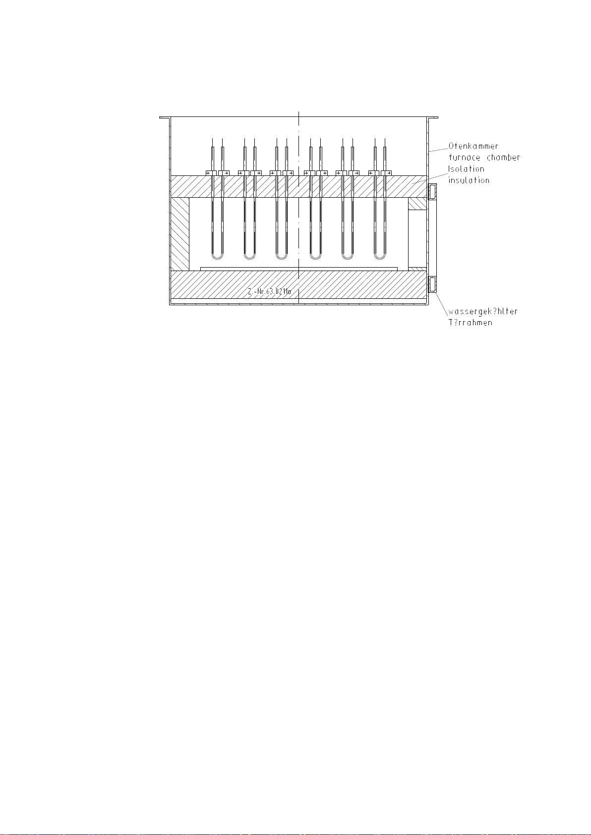
4.2 Insulation
The inner housing is lined with graphite fibre boards. The use of this lightweight, low
heat storage material enables extremely short heating up –and cooling down times.
The bottom insulation is reinforced by fibre light bricks and designed for a max. 50 kg
loading on an area in the furnace centre of 300 x 400 mm.
Additionally the furnace chamber contains an outside wall water cooling (cooling
coil).
The joints (labyrinth) of the insulation will be treated with graphite coating in ordert o
minimize a fibre input in the useful chamber.
4.3 Furnace prepared for the lead –in off three extrusion die
In the centre of the furnace roof a water –cooled blind flange DN 40 KF is provided.
On demand it can be used for lead –in of an extrusion die (pressure force max. 80
kg). From the centre of the furnace roof 2 other water –cooled blind flanges DN 40
Linn High Therm GmbH HT-1500-GT-VAC-Spezial GRAPHITE page 19
operating instruction issue 30.10.2018
_____________________________________________________________________________________________________
KF are provided. On demand it can be used for lead –in off an extrusion die
(pressure force max. 60 kg). The insulation below the flange is provided with a
removable insulating plug d= 40 mm. The furnace bottom is reinforced by fibre light
bricks so that it can carry on 320 x 560 mm a weight of 100 kg or rather per 50 kg
floor loading could be beard on the area of each of both further ducts.
4.4 Oxygen measurement in the exhaust gas line
In the exhaust gas line a gas outlet is foreseen for the separate arrangable oxygen
measurement unit Zr-Ox MK II. On this the unit measures the oxygen content of the
exhaust gas. The measuring range goes from 1 ppm to 99,9 % O2. The display of
the oxygen content is effected also over the temperature programme controller. The
measurement device will be placed on the top control housing. By the separate
construction a fast change of the units for calibration is possible. The signal output to
the controller is 4-20mA (breakdown information).
4.5 Three zone heating
The heating is effected by 12 changeable graphite heating elements which are
operated by 3 three –phase current thyristor units in phase angle control and 3 three
–phase current transformers. The heating element connections are brought out at
the side (zone 1 with 2 heaters, zone 2 with 8 heaters, zone 3 with 2 heaters).
Sidewise, approximately in the centre of each zone, a double thermocouple type
PtRhPt type S each measures the temperature per zone. A thermopair is lead to the
temperature controller and the second one is lead to the safety controller.
4.6 Maximum admissible element temperatures and vacuum
For protective gas operation the maximum admissible temperatures of the heating
elements made of graphite are listed in following table.
The maximum admissible temperature for the furnace chamber is approximately
50°C to 70°C lower than the corresponding value in the table, see also below
remark.
Reaction graphite / CFC with process gases
atmosphere
Start of reaction
reaction
Air
500 ~ 600 °C
Oxidation
Water vapour
700 ~ 750 °C
Oxidation
CO2
800 ~ 900 °C
Oxidation
H2
1000 ~ 1200 °C
Methanisation
N2
2000 ~ 2500 °C
Cyanid - formation
Cl2
2500 °C
evaporation
Ar
3000 °C
evaporation
vacuum
2200 °C
evaporation

Linn High Therm GmbH HT-1500-GT-VAC-Spezial GRAPHITE page 20
operating instruction issue 30.10.2018
_____________________________________________________________________________________________________
* Remark: The information in the tables refer to the heating elements
independent from the furnace. Therefore it can be written a higher
value in the table than this furnace allows due to its construction
type and adjusted safety controller.
The highest admissible furnace temperature is approximately
50°C to 70°C lower than the element temperature.
Graphite heating elements can be applied up to max. 2200 °C in vacuum. The
element temperatures to be achieved are depending on how high the vacuum is(see
vapor pressure diagram). Due to the risk of sublimation (the transition from solid to
gas condition) of the graphite in vacuum (lower than 10-3 ) above of 2.200°C an
operation over 2.200°C in vacuum is not to be recommended.
Operation up to 3000°C is possible in non-oxidizing, reducing, or inert protection gas
atmosphere.
4.7 Over temperature switch-off
Safety controller will switch-off heating after approx. 10 seconds when chamber
temperature exceeds the safety controller’s set value. Red „failure“ ( Störung ) bulb
in button will light.
Re-start can only be effected after pressing button „failure“ ( Störung ); it can only be
initiated when temperature is back in the permitted range, i.e. below value set at
safety controller.
Furnace heating is also switched off in case of breakage of safety thermocouple. In
this case system cannot be re-started when pressing button „failure“ ( Störung ).
4.8 Thermocouples
A double thermocouple S-type, installed from the side in each heating zone,
measures the temperature in furnace chamber. One thermocouple is lead to the
temperature controller, the second to correspondent safety controller.
Thermocouples are exposed to wear, i.e. deviations from standard voltage will occur
in the course of operating hours, and they deviate. Therefore, we recommend to
check thermocouples on regular basis with a calibration thermocouple, to reveal
deviations early.
4.9 Thermocouple safeguard
In case of defective control thermocouple temperature controller will set output power
automatically to 0 %. This avoids uncontrolled heating of the furnace.
Table of contents


