FLIR PTU-D300 User manual

Computer Controlled
PAN-TILT UNIT
Model PTU-D300
USER’S MANUAL
Version 2.19
www.flir.com/mcs

Pan-Tilt Unit (Model PTU-D300) User’s Manual, Version 2.19,
June 25, 2012
©1991,2006 by FLIR Commercial Systems, Inc., 890C Cowan
Road, Burlingame, California 94010, (650)692-3900, FAX:
(650)692-3930, www.flir.com/mcs.
All rights reserved. Protected under numerous U.S. Patents
including 5463432 and 5802412, and patents pending. No part of
this book may be reproduced, stored in a retrieval system, or
transcribed, in any form or by any means, electronic, mechanical,
photocopying, recording, or otherwise, without the prior written
permission of FLIR Commercial Systems, Inc.
The information in this manual is subject to change without notice
and, except for the warranty, does not represent a commitment on
the part of FLIR Commercial Systems, Inc. FLIR Commercial
Systems, Inc. cannot be held liable for any mistakes in this manual
and reserves the right to make changes.

1 INTRODUCTION .................................................................................................1
1.1 IMPORTANT SAFEGUARDS AND WARNINGS....................................2
1.2 Models .........................................................................................................2
2 QUICK START......................................................................................................3
2.1 Overview......................................................................................................3
2.2 Installation Components ..............................................................................3
2.3 Basic Setup Steps.........................................................................................4
3 INSTALLATION & INITIAL SETUP ................................................................5
3.1 Pan-Tilt Mounting........................................................................................5
3.2 Wiring and Connectors ................................................................................5
3.3 Power Sources..............................................................................................6
3.4 RS-232 Interface and Host Settings.............................................................7
3.5 Initial Power-up and Test.............................................................................8
3.6 Basic Pan-Tilt Unit Commands ...................................................................8
3.7 Mounting Your Payload...............................................................................8
3.7.1 Over-the-Top Bracket Mounting......................................................9
3.7.2 Side-Mount Bracket Mounting........................................................9
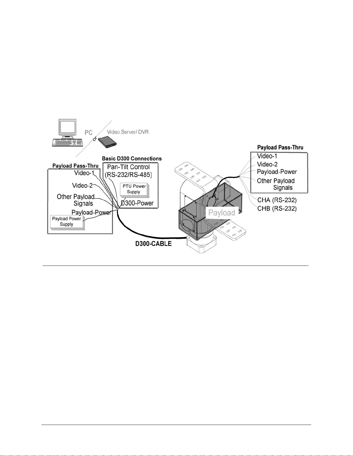
3.8 Payload Wiring Connections .....................................................................10
4 COMMAND REFERENCE................................................................................11
4.1 Binary Command Format ..........................................................................11
4.2 General ASCII Command Format.............................................................11
4.3 Positional Control Commands & Queries .................................................11
4.3.1 Position (absolute) .........................................................................11
4.3.2 Offset Position (relative offset)......................................................12
4.3.3 Resolution per Position..................................................................12
4.3.4 Limit Position Queries...................................................................13
4.3.5 Position Limit Enforcement...........................................................13
4.3.6 Immediate Position Execution Mode.............................................14
4.3.7 Slaved Position Execution Mode...................................................14
4.3.8 Await Position Command Completion ..........................................15
4.3.9 Halt Command...............................................................................15
4.3.10 Monitor (Autoscan) Command......................................................16
4.3.11 Position Presets..............................................................................16
4.4 Speed Control Commands & Queries........................................................17
4.4.1 Speed Control & Relevant Terms..................................................17
4.4.2 Speed (absolute).............................................................................17
4.4.3 Delta Speed (relative offset) ..........................................................18
4.4.4 Acceleration...................................................................................19
4.4.5 Base (Start-Up) Speed....................................................................19
4.4.6 Speed Bounds ................................................................................20
4.4.7 Speed Control Modes.....................................................................20
4.5 Unit Commands.........................................................................................21

4.5.1 Reset Pan-Tilt Unit ........................................................................21
4.5.2 Default Save/Restore .....................................................................22
4.5.3 Echo Query/Enable/Disable...........................................................22
4.5.4 Feedback Verbose/Terse/Off..........................................................23
4.5.5 Controller Firmware Version Query ..............................................23
4.5.6 Outside Supply Voltage and Controller Temperature Query.........23
4.6 Power Control Commands & Queries .......................................................23
4.6.1 Stationary Power Mode..................................................................24
4.6.2 In-Motion Power Mode .................................................................24
4.7 Host Serial Port and Control......................................................................25
4.7.1 Configuring Host Serial Port Baud and Communications.............25
4.8 Step Modes.................................................................................................26
4.8.1 Configuring Step Mode..................................................................26
5 SPECIAL CONFIGURATIONS ........................................................................27
5.1 High-Speed Operation ...............................................................................27
5.2 High-Payload Operation ............................................................................27
5.3 Battery-Powered Operation .......................................................................27
6 PTU OPTIONS ....................................................................................................28
6.1 EIO Option: Expansion Serial Ports and Control......................................28
7 NETWORKING...................................................................................................28
7.1 Basic Networking Setup Steps...................................................................28
7.2 PTU Network Connections........................................................................29
7.3 PTU Network Software Commands ..........................................................29
7.3.1 Unit Network ID............................................................................29
7.3.2 Unit Select/Deselect.......................................................................30
A. SPECIFICATIONS..............................................................................................31
A.1 D300 Mechanical Dimensions...................................................................31
A.2 D300 Payload Bracket Dimensions...........................................................32
A.3 D300 Base Connector Wiring....................................................................33
A.4 D300 Payload Wiring PL01.......................................................................34
A.5 D300 Payload Wiring PL02.......................................................................35
A.6 D300 Payload Mounting............................................................................36
REGULATORY INFORMATION.....................................................................37
LIMITED WARRANTY.....................................................................................38

PTU-D300 User’s Manual (v2.19) INTRODUCTION
page 1
1 INTRODUCTION
The PTU-D300 Pan-Tilt Unit from FLIR Commercial Systems, Inc. provides fast, accurate,
and durable positioning of cameras, antennas, lasers, and other large payloads. Some general
features:
• Simple to command from any RS-232 or RS-485 terminal or computer
• Payload capacity up to 35-70 lbs.
• Resolution of 0.02 degrees
• Precise control of position, speed & acceleration
• On-the-fly position and speed changes
• Self calibration upon reset
• Power consumption can be controlled from host
• ASCII command mode for simplicity, binary commands available for efficient program
control
• Constant current DMOS motor drives for increased performance and control
• DC power input from an unregulated source
• Flexible connectivity options.
Applications of the PTU-D300 include:
• Mid and Long-range Surveillance systems
• Automated detection and tracking
• Multi-sensor perimeter monitoring systems
• Thermal and IR cameras
• Marine/shipboard sensor systems
• Harbor and Port Security
• Border Security & Law Enforcement
• Highway & Transportation Monitoring
• Military special operations
• Satellite communications systems
• Microwave antenna systems (passive, active)
• Robotics & computer vision.
This User’s Manual provides information needed to set up and operate the PTU-D300 unit. The
next section provides a brief overview to allow you to get started as quickly as possible. More
detailed technical information is provided in the remaining sections.

page 2
INTRODUCTION PTU-D300 User’s Manual (v2.19)
1.1 IMPORTANT SAFEGUARDS AND WARNINGS
IMPORTANT SAFEGUARDS AND WARNINGS
1. Please read these instructions prior to use.
2. Please keep these instructions accessible.
3. Please heed all warnings.
4. Please follow all instructions.
5. Installation should be done only by qualified personnel and conform to all local codes.
CAUTION: These servicing instructions are for use by qualified service personnel only.
To reduce the risk of electric shock, do not perform any servicing other than that contained
in the operating instructions unless you are qualified to do so.
6. Use only mounting methods and materials capable of supporting at least four times the
combined weight of the D300 pan-tilt, mounted payloads, and cabling.
7. For outdoor use, use only corrosion resistant hardware to fasten the mount and payloads
(e.g., stainless steel screws).
8. The unit should not be installed in environments that present conditions beyond the
environmental specification of the D300. Installation near heat sources such as radiators,
heat registers, stoves, or other apparatus (including amplifiers) can exceed the unit’s
temperature ratings.
9. Refer all servicing to qualified service personnel. If the unit is damaged, remove power
immediately, and contact FLIR Commercial Systems, Inc.
10. A readily accessible power disconnect shall be incorporated into the installation wiring.
11. Only use replacement parts recommended by FLIR Commercial Systems, Inc.
1.2 Models
PTU-D300 Standard base configuration. Includes basic slip-ring, integral controller, stan-
dard convertible “L” bracket.

PTU-D300 User’s Manual (v2.19) QUICK START
page 3
2 QUICK START
2.1 Overview
Figure 1 shows a system overview. The PTU-D300 includes an integral controller and it
accepts control commands from any host computer over RS-232 or RS-485. The basic D300
connections are: D300-power from a DC power source, and Pan-Tilt Control via RS232/485.
In addition to pan-tilt control connections, “Payload Pass-Thru” internally routes payload
signals such as video, payload power, and other payload connections from a single stationary
connector in the PTU base to a single payload connector that moves with your payload.
The PTU-D300 can be controlled from any host computer using the built-in ASCII protocol
described in this manual. For high speed, hard real-time controls (such as tracking), a binary
protocol is supported via a C Programmers Interface (PTU-CPI). Drivers are also available in 3rd
party software packages such as LabView and digital video control systems.
2.2 Installation Components
Components supplied with this manual are:
• Pan-Tilt Unit
• Standard Payload Mounting Bracket
• Pan-Tilt Cable Harness - Optional
• AC/DC Power Supply - Optional
Figure 1: Pan-Tilt System Overview

page 4
QUICK START PTU-D300 User’s Manual (v2.19)
2.3 Basic Setup Steps
The following outlines the basic pan-tilt set-up and installation steps. Section 3 details each
of these steps.
1. Unpack the D300 pan-tilt. Mount the pan-tilt securely. See section 3.1 for details on
mounting.
2. Establish wiring to the pan-tilt. Factory cable with breakouts for power and other
connections makes this easy (model PTU-CAB-25BO). Or you can make your own cables
that better suit your installation.
3. Connect an RS-232 or RS-485 cable between Pan-Tilt Control input and a host computer.
When using factory cable PTU-CAB-25BO, standard RS232 connection (DB9F) is
provided. HyperTerminal (built into Windows) is the most commonly used comm program.
Communications parameters are: 9600 baud, no parity, no handshaking. (see Section 3.4).
4. Provide DC power to the pan-tilt. When using factory cable PTU-CAB-25BO, easy plug-in
power is provided by AC/DC power supply model PTU-APS-30V. Or you can obtain your
own DC power source that better suits your installation. Always incorporate a readily-
accessible power disconnect into the installation wiring. Removing power by disconnecting
the power cable or cable harness is not recommended and can cause damage to the system.
5. Power up the pan-tilt. If power is working, the unit will go through a power-up calibration.
At power up, the pan-tilt defaults to providing splash text on your terminal that will identify
the unit configuration. Pan-tilt operation can then be tested by typing commands into your
terminal program.
6. Section 3.6 describes some basic pan-tilt commands to get you going. Section 4 provides a
full description of all pan-tilt unit commands and queries.
7. You can now mount and wire your payload (e.g., camera) on the pan-tilt unit (see Section
3.8).

PTU-D300 User’s Manual (v2.19) INSTALLATION & INITIAL SETUP
page 5
3 INSTALLATION & INITIAL SETUP
This section describes the basic installation and setup steps required to get your pan-tilt
operational as quickly as possible.
3.1 Pan-Tilt Mounting
Appendix 1 shows the mounting pattern for the PTU-D300. The basic mounting pattern is
four #1/4-20 socket-head cap screws in a 3.375” (85.725mm) square pattern. All four mounting
screws should be used. The mount strength must be able to hold the weight of the unit plus the
payload plus any additional forces exerted on the system (e.g., wind, G forces). A good rule of
thumb: the mount must support at least four times the combined weight of the payload plus the
weight of the pan-tilt (e.g., a 25 lb. payload mounted to the D300 must support at least 205 lbs).
CAUTION: FAILURE TO SECURE THE PAN-TILT AND ITS PAYLOAD
TO A SUFFICIENTLY STRONG MOUNTING CAN RESULT IN
DAMAGE TO THE PAN-TILT, THE PAYLOAD, OR POSSIBLE INJURY
OR DEATH. YOU MUST ENSURE THE MOUNTING IS CAPABLE OF
HOLDING THE LOADS!
3.2 Wiring and Connectors
Figure 2 shows a back view of the D300. The D300 base connector is a MIL-C-26482
compatible receptacle (19 pins). Appendix A.3 shows the D300 base connector signals and
wiring. Basic control requires that you connect a DC power source to the D300-power input, and
a host computer connection (to HOST-232 or HOST-485) to communicate and control the D300.
Figure 2: Wiring Overview
PAYLOAD
CONNECTOR
D300 BASE
CONNECTOR

page 6
INSTALLATION & INITIAL SETUP PTU-D300 User’s Manual (v2.19)
The easiest way to wire into the D300 is to use the factory cable with breakouts for power
and other connections (model PTU-CAB-25BO), and to use the factory power supply (model
PTU-APS-30V). This allows you to plug in and run the D300 in minutes. Or you can use the
wiring diagram in Appendix A.3 to make your own cables that better suit your installation.
Connect an RS-232 or RS-485 cable between the D300 and a host computer. When using the
factory cable PTU-CAB-25BO, standard RS232 connection (DB9F) is provided. HyperTerminal
(built into Windows) is the most commonly used communications program. Communications
parameters are: 9600 baud, no parity, no handshaking. (see Section 3.4).
The D300 provides payload pass-thru signals that connect between pins in the base
connector to corresponding pins in the payload connector. Additional pins in the payload
connector provide other payload controls (auxiliary RS232 ports and TTL control). Figure 2
shows this payload connector which is also a MIL-C-26482 compatible receptacle (19 pins).
Appendix A.4 details the payload connector pin-out.
Appendix A.4 shows the payload connector wiring. Pins highlighted in red indicate payload
pass-thru signals connected to corresponding pins in the base connector.
When attaching payload signals to the system, care must be taken to adhere to all
specifications for the pass-thru signals, such as maximum voltage and current
levels.
3.3 Power Sources
The PTU-D300 requires a 12-30VDC (unregulated) power source capable of 2.25A peak.
Less peak current is required if you do not use the higher motor current controls available (see
Sections 4.6.1 and 4.6.2). To achieve the highest pan-tilt unit performance, use the highest motor
voltage within the allowable range. To achieve the quietest and smoothest pan-tilt operation, you
can use a lower motor voltage (e.g., 12VDC).
When wiring your own power source, failure to comply with wiring and power source
requirements described in this manual can result in decreased unit
performance or damage not covered under the limited warranty.
If you are providing your own DC power source, the power source must never supply
more than rated current, and if so, you must add a fuse in series with your DC power
source. For example, when connecting to a vehicle battery or lighter plug, you must fuse the
incoming DC source. Failure to properly fuse your input power source could cause overloading of
internal protection devices, pose a safety hazard, or void product warranties.

PTU-D300 User’s Manual (v2.19) INSTALLATION & INITIAL SETUP
page 7
3.4 RS-232 Interface and Host Settings
An RS-232 terminal or host computer connects to the RS-232 Host Interface on the Pan-Tilt
Unit. The host terminal or computer should be set to 9600 baud, 1 start bit, 8 data bits, 1 stop bit,
and no parity. Hardware handshaking and XON/XOFF are not used.
The RS-232 connections to the Pan-Tilt are: TxD (pin 2), RxD (pin 3), and GND (pin 5).
Figure 3 shows cable configurations for some common computer hosts. Since TxD and RxD
assignments to pins 2 and 3 can vary on host computers, try using a null modem if your initial
connection does not work.
Figure 3: RS-232 Pan-Tilt Controller Connection to Common Hosts
RxD (pin 3)
TxD (pin 2)
GND (pin 5)
IBM PC
DB-25S
TxD (pin 2)
RxD (pin 3)
GND (pin 7)
PTU-CAB-25BO
(female DB-9)
TxD (pin 2)
GND (pin 5)
IBM PC
DB-9S
RxD (pin 2)
TxD (pin 3)
GND (pin 5)
(female DB-9)
TxD (pin 2)
RxD (pin 3)
GND (pin 5)
Apple Macintosh
8 Pin Mini-DIN
TxD (pin 3)
RxD (pin 5)
GND (pin 4)
RxD (pin 3)
Null modem may
be required.
DTR (pin 4)
DSR (pin 6)
DTR (pin 20)
DSR (pin 6)
(pin 4)
(pin 6)
(pin 4)
(pin 6)
DTR (pin 1) (pin 4)
(pin 6)
DSR (pin 2)
PTU-CAB-25BO
(female DB-9)
PTU-CAB-25BO
RxD (pin 3)
TxD (pin 2)
GND (pin 5)
D300 Base Connector (19 pins)
MIL-C-26482 compatible receptacle
pin L
pin K
pin J
PTU-CAB-25BO
(female DB-9)

page 8
INSTALLATION & INITIAL SETUP PTU-D300 User’s Manual (v2.19)
3.5 Initial Power-up and Test
If you have the power source and Host computer connected described in Sections 3.3 and 3.4,
you are ready to power-up and test its operation. Test and verify all cable connections and
connector wiring before power-up. We suggest that you do not mount your payload (e.g., camera)
until this initial installation is completed and tested.
1. Using HyperTerminal or a similar terminal program, configure the RS-232/485 serial port of
the Host Computer to 9600 baud, 1 start bit, 8 data bits, 1 stop bit, and no parity. Hardware
handshaking and XON/XOFF are not used.
2. You are now ready to power up the pan-tilt unit and test its operation. Apply power. Upon
power up, introduction text should appear on your screen, and the pan-tilt unit should go
through a reset cycle (pan and tilt axes will cycle through their full range of motion). This
reset is completed when an asterisk (‘*’) appears. If the unit did not reset properly, recheck
your power source and cabling. If the unit went through its reset procedure, but no text or
garbled text appears on your screen, then:
• Check that the host RS-232/RS-485 host port settings are correct (see Section 3.4)
• Check that the RS-232/RS-485 cable is correct for your host (see Section 3.4)
3. You are now connected to the pan-tilt. Enter the character ‘?’ for a complete listing of
commands. The next section describes some basic commands to help you get going, and a
full command description may be found in Section 4. We suggest that you exercise the unit
and become familiar with its operation and commands before mounting your payload (e.g.,
camera) as described in Section 3.8. Special attention should be paid to acceleration and
speed commands, and they should be set at levels appropriate to your payload weight and
size.
3.6 Basic Pan-Tilt Unit Commands
Below are some pan-tilt commands that will familiarize you with the pan-tilt unit and its
operation:
pp2500 *
tp-900 *
PS1900 *
pp0 *
This sets the pan axis to position 2500, the tilt axis to position -900, the pan speed to 2500
positions a second, and sets the pan position back home.
When operating the pan-tilt unit, the available command menu is printed when you enter the
‘?’ character. A detailed description of pan-tilt commands and queries may be found in Section 4.
3.7 Mounting Your Payload
The PTU-D300 sports a flexible payload bracket system that can be configured in a number
of ways to support a variety of payloads including cameras, lasers, antennas, and other equipment.
Because of the heavy payload weights and high potential speeds supported by the PTU-D300, it is
very important that all guidance and instructions regarding payload mounting be followed
carefully.

PTU-D300 User’s Manual (v2.19) INSTALLATION & INITIAL SETUP
page 9
3.7.1 Over-the-Top Bracket Mounting
1. Ensure the pan-tilt has been through its calibration (at power up) so that the mounting hub is
in a known home position.
2. Orient the bracket so the horizontal part of the bracket is topmost. When in the proper
orientation, a peg in the bracket will locate into a hole in the D300 mounting hub.
3. Attach the bracket using 6pcs screws.
It is vital that thread lock is used for the bracket mounting screws. The thread
holes in the hub have thread lock applied to them. If the bracket is removed,
you should apply medium strength thread lock to the hub (e.g., Loctite 242).
4. Reset the pan-tilt and ensure that the bracket moves properly through its range of motion.
3.7.2 Side-Mount Bracket Mounting
1. Ensure the pan-tilt has been through its calibration (at power up) so that the mounting hub is
in a known home position.
2. Orient the bracket so the horizontal part of the bracket is bottommost.
3. Attach the bracket using 6pcs screws.
It is vital that thread lock is used for the bracket mounting screws. The thread
holes in the hub have thread lock applied to them. If the bracket is removed,
you should apply medium strength thread lock to the hub (e.g., Loctite 242).
4. Reset the pan-tilt and ensure that the bracket moves properly through its range of motion.
Figure 4: Payload Bracket Mounting

page 10
INSTALLATION & INITIAL SETUP PTU-D300 User’s Manual (v2.19)
Payloads should be mounted as close to the Pan-tilt housing as possible so as to position the
center of gravity as close to the pan-axis as possible.
In all cases, care must be taken to ensure that the payload will clear the Pan-tilt
housing and surrounding objects throughout the full range of motion of the unit.
Though the PTU-D300 unit is rated to a maximum load of 70 lbs, the distribution of the load
affects the actual load capable of being moved by the pan-tilt unit. The steps to determine whether
your load and its positioning (e.g., center of gravity) are within the maximum load capacity and
dynamics are:
• Mount your payload. Side-mount is preferred for heavier loads, as it keeps the payload
center of gravity closer to the tilt axis of rotation thereby minimizing torque requirements.
Ensure that the load is securely attached to the payload bracket.
• First move the pan axis through its range to test whether the pan-tilt can handle the load
(e.g., enter “dr pp2700 a pp-2700 a pp0 ”). A load that is too heavy or moved too
quickly will cause the unit to lose synchrony, and this will be accompanied by an audible
“rrrr” sound from the pan-tilt unit motors. See section 5.2 on page 27 for further information
on configuration of the Pan-Tilt for heavier payloads.
• If your load passed the pan axis load test, you can then test the tilt axis load handling
capability. The center of gravity for top mounted payloads is further from the tilt axis of
rotation, and this may require more torque to move the load. Move the tilt axis through its
range of motion to test whether the pan-tilt can handle the load (e.g., enter “DR TP-900 A
TP600 A TPp0 “). A load that is too heavy or moved too quickly will cause the unit to
lose synchrony, and this will be accompanied by an audible “rrrr” sound from the pan-tilt
unit motors.
• If your load fails the above pan or tilt axis load handling tests, check Section 5.2 for further
information. Significantly faster or lower power control can be obtained via commands to
the pan-tilt unit. The speed and acceleration of a mechanical system depends upon the
inertial properties of your load. The ability of the pan-tilt unit to successfully move your
load without losing synchrony depends upon the inertial load factors and their relationship
to power supply voltage, unit speed, acceleration, position, motor torque, etc. Section 5.2
discusses how to configure pan-tilt parameters to achieve more optimal pan-tilt unit
performance for your load. If you have questions about your payload mounting or load
handling, please contact Technical Support for further assistance.
• If your load passes the above pan and tilt axis load handling tests, you are ready to begin
controlling your load using the commands described in Section 4.
3.8 Payload Wiring Connections
The D300 provides payload pass-thru signals that connect between pins in the base
connector to corresponding pins in the payload connector. Additional pins in the payload
connector provide other payload controls (auxiliary RS232 ports and TTL control). Figure 2
shows this payload connector which is also a MIL-C-26482 compatible receptacle (19 pins).
Appendix A.4 details the payload connector pin-out. Your payload connects to the payload
connector via a male MIL-C-26482 compatible plug (e.g., PT06A14-19P).
Appendix A.4 shows the payload connector wiring. Pins highlighted in red indicate payload
pass-thru signals connected to corresponding pins in the base connector.
When attaching payload signals to the system, care must be taken to adhere to all
specifications for the pass-thru signals, such as maximum voltage and current
levels.

PTU-D300 User’s Manual (v2.19) COMMAND REFERENCE
page 11
4 COMMAND REFERENCE
This section describes the pan-tilt unit command set. Each command has a section that
provides a brief functional description, a format (syntax) description, examples, and related
topics. When controlling the pan-tilt unit from a terminal, a complete menu of pan-tilt commands
can be obtained by entering the character “?”.
4.1 Binary Command Format
A C Programmer’s Interface (model PTU-CPI) is available for higher bandwidth binary
communications between a host computer and the PTU controller.
4.2 General ASCII Command Format
When describing the format (syntax) of pan-tilt commands, the following conventions are
adopted:
• Commands issued to the pan-tilt unit (e.g., typed in by you) are shown in bold.
• Input characters may be in upper or lower case (we show them in upper case for
presentational consistency)
• A delimiter (<delim>) can be either a space (“ ”) or a carriage return (<CR>).
• A successfully executed command returns “*<CR>”. Successful query execution returns
“* <QueryResult><CR>”. Command execution failure returns
“! <ErrorMessage><CR>”. A pan axis limit hit asynchronously returns “!P” and a tilt
axis limit hit asynchronously returns “!T”.
4.3 Positional Control Commands & Queries
4.3.1 Position (absolute)
Description:
Specify or query the absolute pan or tilt axis position. Desired positions can
be changed on-the-fly without waiting for previous position commands to
complete.
Syntax Query current absolute pan position: PP<delim>
Set desired absolute pan position: PP<position><delim>
Query current absolute tilt position: TP<delim>
Set desired absolute tilt position: TP<position><delim>
ExampleThe following sends the pan axis to the left, waits, then sends it to the right:
PP-2500 *
A*
PP * Current Pan position is -2500
PP2500 *
A*
PP * Current Pan position is 2500

page 12
COMMAND REFERENCE PTU-D300 User’s Manual (v2.19)
Related Topics
• Position (relative offset and desired position queries): See Section 4.3.2
• Position resolution (units): See Section 4.3.3
• Position limits: See Section 4.3.4
• Position execution modes: See Sections 4.3.6, 4.3.7 and 4.3.8
• Position limit enforcement modes: See Section 4.3.5
4.3.2 Offset Position (relative offset)
Description
Specify desired axis position as an offset from the current position, or Query
the current axis position. Desired offset positions can be changed on-the-fly
without waiting for previous position commands to complete.
Syntax Query desired pan position: PO<delim>
Set desired offset pan position: PO<position><delim>
Query desired tilt position: TO<delim>
Set desired offset tilt position: TO<position><delim>
ExampleThe following sends the pan axis to position -500, then sends it 1500
positions to the left:
PP-500 *
A*
PO * Current Pan position is -500
PO1500 *
A*
PP * Current Pan position is 1000
Related Topics
• Position resolution (units): See Section 4.3.3
• Position limits: See Section 4.3.4
• Position execution modes: See Sections 4.3.6, 4.3.7 and 4.3.8
• Position limit enforcement modes: See Section 4.3.5
4.3.3 Resolution per Position
Description
Query returns the axis resolution per position moved (in seconds/arc).
Syntax Query pan resolution: PR<delim>
Query tilt resolution: TR<delim>
ExampleResolution can be determined by:
PR * 92.5714 seconds arc per position
1 sec arc = 1/(60 min arc * 60 sec arc) = .0002778°. So 92.5714 seconds
arc equals (92.5714 sec arc * .002778°) = 0.025716335°. Thus, to pan 21.3°
left requires a relative move of (21.3°/0.025716°) 828 positions, yielding
the following command:
PO828 *

PTU-D300 User’s Manual (v2.19) COMMAND REFERENCE
page 13
Related Topics
• Factory options are available to achieve higher resolution or accuracy.
4.3.4 Limit Position Queries
Description
Queries return the axis position bounds determined upon unit reset.
Syntax Query minimum pan position: PN<delim>
Query maximum pan position: PX<delim>
Query minimum tilt position: TN<delim>
Query maximum tilt position: TX<delim>
Example R*
PN * Minimum Pan position is -3090
PX * Maximum Pan position is 3090
TN * Minimum Tilt position is -907
TX * Maximum Tilt position is 604
LE *
PP3200 ! Maximum allowable Pan position is 3090
Related Topics
• Position resolution (units): See Section 4.3.3
• Achieving larger axis bounds: See Section 4.3.5
4.3.5 Position Limit Enforcement
Description
Determines whether position commands beyond the detected pan axis limits
are allowable. The default is pan position limits are enabled (i.e., enforced).
When limits are enabled, commands outside of the limits return an error
message and are not executed. In enabled limit mode, limits are only reached
when the unit has lost synchrony and this error condition requires a unit reset
(see Section 4.5.1). When a limit is reached, a “!P” is printed to the host serial
port to indicate that the pan axis limit was hit.
When larger operational pan ranges are required, the limits may be
disabled. Positional pan commands outside the limits are not rejected when
limits are disabled.
Syntax Query current pan position limit mode: L<delim>
Enable pan position limits: LE<delim>
Disable pan position limits: LD<delim>
Example L* Limit bounds are ENABLED (soft limits enabled)
PX * Maximum Pan position is 3090
PP3200 ! Maximum allowable Pan position is 3090
LD *
PP3200 *
A*
PP * Current Pan position is 3200

page 14
COMMAND REFERENCE PTU-D300 User’s Manual (v2.19)
Related Topics
• Position commands: See Sections 4.3.1 and 4.3.2
4.3.6 Immediate Position Execution Mode
Description
Instructs pan-tilt unit to immediately execute positional commands. This is
the default mode.
Syntax I<delim>
ExampleFor the below commands, the pan axis will immediately execute the pan
position command:
I*
PP1000 *
Related Topics
• Alternative slaved position execution mode: See Section 4.3.7
4.3.7 Slaved Position Execution Mode
Description
Instructs pan-tilt unit to execute positional commands only when an Await
Position Command Completion command is executed (see Section 4.3.8) or
when put into Immediate Execution Mode (see Section 4.3.6). This mode is
useful when coordinated pan and tilt axis movements are desired.
Syntax S<delim>
ExampleThe following commands change the position execution mode, instruct the
axes which position to achieve, and an await command causes the position
commands to be executed simultaneously:
DR *
S*
PP1500 *
TP-900 *
PP * Current Pan position is 0
TP * Current Tilt position is 0
A*
PP * Current Pan position is 1500
TP * Current Tilt position is -900
Related Topics
• Alternative immediate position execution mode: See Section 4.3.6

PTU-D300 User’s Manual (v2.19) COMMAND REFERENCE
page 15
4.3.8 Await Position Command Completion
Description
Awaits the completion of the last issued pan and tilt axis position commands.
Used to coordinate axis motions.
Syntax A<delim>
ExampleThe following commands instruct the pan axis to move to a position, then
move to another position:
I*
PP * Current Pan position is 0
PP2000 *
A*
PP * Current Pan position is 2000
PP0 *
A*
PP * Current Pan position is 0
In contrast, the following commands would begin to move to the first
position, and before that position is reached, the next position would be
moved towards (this is often called an on-the-fly position change):
I*
PP * Current Pan position is 0
PP2000 *
PP0 *
Related Topics
• This command can be used for both the Immediate Position Execution
Mode (see Section 4.3.6) and Slaved Position Execution Mode (see Section
4.3.7)
4.3.9 Halt Command
Description
Immediately decelerates and halts pan-tilt movement.
Syntax Halt all pan-tilt movement: H<delim>
Halt pan axis movement: HP<delim>
Halt tilt axis movement: HT<delim>
Example PP2500 *
A*
PP-2500
Then while the pan-tilt is moving, the host decides to stop immediately:
H*
Related Topics
• This command can be used for both the Immediate Position Execution
Mode (see Section 4.3.6) and Slaved Position Execution Mode (see Section
4.3.7)

page 16
COMMAND REFERENCE PTU-D300 User’s Manual (v2.19)
4.3.10 Monitor (Autoscan) Command
Description
Command defines and initiates repetitive monitoring (scanning) of the pan-
tilt. Autoscanning is immediately terminated upon receipt of a character from
the host computer, and the pan-tilt is sent to its home position.
Syntax Initiate monitor (autoscan) in pan axis only:
M<pan pos 1>,<pan pos 2><delim>
Initiate monitor (autoscan) in both pan and tilt axes:
M<pan pos 1>,<pan pos 2>,<tilt pos 1>,<tilt pos 2><delim>
Initiate last defined monitor (autoscan) command (the default at power up is
pan axis only autoscan between the pan limit positions):
M<delim>
Enable monitor (autoscan) at power up: ME<delim>
Disable monitor (autoscan) at power up: MD<delim>
Query monitor status at power up: MQ<delim>
Example When executed at power up,
M*
the pan-tilt begins scanning between the minimum and maximum pan limit
positions.
<delim>
terminates the scanning and homes the pan-tilt. Other monitoring command
forms:
M-2500,100 *
M-2500,100,-800,600 *
M0,0,-300,300 *
Related Topics
• Limit Position Queries (see Section 4.3.4)
4.3.11 Position Presets
Description
Position preset functionality is provided for backward compatibility with
legacy CCTV applications. D300 pan-tilt controller firmware version v2-12-
11r2 and higher support position presets. The pan-tilt can be commanded to a
position using any of the standard motion control commands of the D300
PTU. The current pan and tilt position can be stored as a numbered “preset”.
The PTU can then be commanded to a previously stored preset using a new
“go to preset” command. Currently set motion parameters (acceleration, base
rate, etc.) apply during “go to preset” commands. Preset positions are
remembered when the controller is repowered.
Syntax XS<index><delim> where <index> ? [0..32] “Set Preset”
XG<index><delim> where <index> ? [0..32] “Goto Preset”
XC<index><delim> where <index> ? [0..32] “Clear Preset”
ExampleThe following commands set the Pan/Tilt to position 500/400, store as preset
0, move the unit to position 600/800, and then goes back to previously stored
preset 0 position.
Other manuals for PTU-D300
1
Table of contents
Other FLIR Camera Accessories manuals