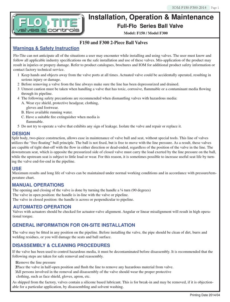
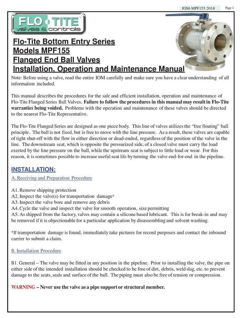
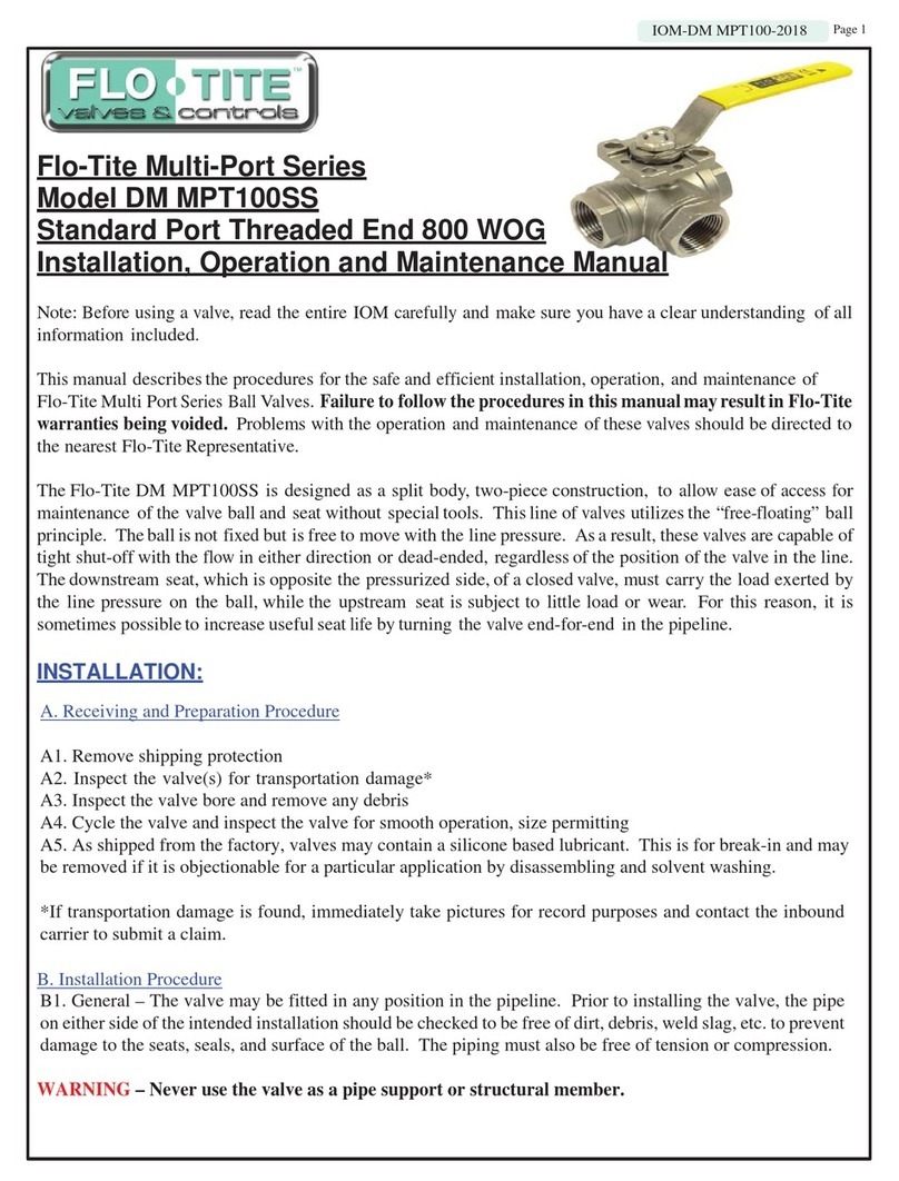
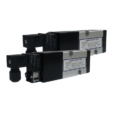
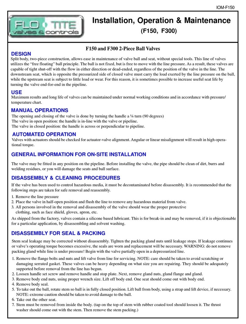
Flo-Tite MPF15 Owner's manual

Installation, Operation & Maintenance
IOM-MPF15-01
2. USE
Maximum results and long life of valves can be maintained under normal working conditions and in accordance with
proper pressure/temperature and corrosion data.
3. MANUAL OPERATIONS
5. DISASSEMBLY & CLEANING PROCEDURES
1. ON-SITE INSTALLATION
The manual operation for the proper flow plan is done by turning the handle a 1/4 turn (90 degree turn).
Visual indication of position is done by visual inspection of the markings on the top of the stem.
If the valve has been used to control hazardous media, it must be decontaminated before disasembly. It is
recommended that the following steps are taken for safe removal and reassembly.
1. Relieve the line pressure
2. Place valve in half-open position and flush the line to remove any hazardous material from valve
3. All persons involved in the removal and disassembly of the valve should wear the proper protective clothing, such as face
shield, glove, apron and etc.
The valve may be fitted to any position on the pipeline.
Before installation, pipes must be flushed clean of dirt and debris that could result in damage to hard or soft parts of the valve.
Piping must be supported so as not to add undue stress to the valve.
MPF15 3-Way Ball Valves
Valves come shipped from the factory containing a lubricant. This is for break-in and may be removed if it is objectionable to
a particular application by disassembly and cleaning with a proper solvent.
DESIGN:
Central body design, three-flanged end piece construction, allows ease of maintenance, without special tools. This type
of valve utilizes a true trunnion ball principle. The ball is fixed, it is not free to move with line pressure. This particular
feature allows tight shut-off to flow in either direction or dead ended, regardless of the position of the valve in-line.
4. AUTOMATED OPERATIONS
Valves with actuators should be checked for actuator/valve alignment. Angular or linear mis-alignment will result in high
operational torque and premature packing failure.
6. DISASSEMBLY FOR STEM AND SEAL REMOVAL
Stem seal leakage may be corrected without disassembly by tightening the packing gland bolts until such leakage stops.
If the leakage continues or valve operating torque becomes excessive, or the stem seals are worn, replacement will be
necessary.
Remove flange bolts and nuts and lift valve from line for servicing. NOTE: care should be taken to avoid scratching or damag-
ing serrated flange faces. Valves can be heavy, they should be adequately supported before removal from the line has begun.
Loosen handle set screw and remove handle and stop plate. Remove gland nuts and packing gland. Mark each flange to the
body joint (3 flanges). Mark top cap to the body joint. This is to allow ease of alignment in reinstallation.
Remove the nuts holding flanged pieces and top cap for disassembly.
Remove all three end pieces, then the top cap, leaving the ball to last.
Take extreme care when removing ball as not to scratch seating surface or the stem, which will result in leakage after reassem-
bly.
Remove all seats, seals and the thrust bearing.
Note: If the valve is supplied with body cavity fillers:
Cavity filler is supplied in two parts: top and bottom. They are removed after the top cover and end caps are removed. Remove
top half then valve ball, then bottom cavity filler.
(CAUTION: Ball valves can trap fluids in ball cavity when closed)
(Warning: Do not remove the packing gland while line is under pressure! )
Page 1

Please carefully review all important procedures in this manual. If anything is
not clear, please feel free to contact Flo-Tite directly
7. RECOMMENDED SPARE PARTS
The recommended spare parts for normal service conditions are the “soft” parts contained in the repair kit available from FTI;
stem seals, body seals and seats. For more severe conditions, spare balls and stems may be needed.
8. VISUAL INSPECTION
Clean and inspect metal parts. It is not necessary to replace the ball and stem unless the seating surface have been damaged by
abrasion or corrosion. We strongly recommend of all soft parts whenever the valve is disassembled from reconditioning. This
is the best protection against valve leakage after assembly. Replacement parts can be ordered in kit form. NOTE: the valve
may be assembled and operated dry where no lubricants are allowed in the system; however, a light lubrication of mating
parts will aid in assembly and reduce initial operating torque. Lubricant used must be compatible with intended line content.
9. ASSEMBLY
Install the thrust bearing in the bottom center of the body.
Install the ball in the body, making sure the trunnion of the ball goes into the thrust bearing.
Install the seats in each of the flanged end pieces with spherical curvature facing the mating ball.
Install the top cap and body gasket making sure to align the marks made during disassembly. Tighten down in a criss-cross
pattern. Keep gap even. This will insure the valve stop or actuator is in the proper position.
Now install the packing and packing gland with packing gland bolts. Tighten bolts evenly.
The installation of the flanged end pieces must be done in the following way to insure damage.
First install the left and right end pieces with the nuts aligning the marks made during disassembly. This is to insure flange-
to-flange mating and alignment of the valve bolt holes. Make sure the ball ports are aligned with the end pieces as not to
pinch the seats during tightening. Do not tighten one end piece fully until both ends are installed. Due to the location, the nuts
should be torqued down evenly using a criss-cross pattern and alternating between each end until metal-to-metal contact is
achieved. During this step, check body to end piece gap and keep gap consistent. Uneven tightening may result in pinching of
the seats and subsequent leakage after reassembly.
The installation of the center end piece is done first by rotating the ball until the blind side of the ball is facing area where the
end piece is being installed, aligning previous marks. Tighten the nuts using a criss-cross pattern. Make sure the gap of the
end piece to valve remains consistent metal-to-metal contact is achieved.
Cycling the valve slowly back to the proper flow plan by turning the ball slowly insures the seal lips assumes a permanent seal
against the ball. A fast turning motion may not allow proper mating to occur.
Test valve, if at all possible, prior to placing valve back into line.
WARNING: Not properly securing valve may cause it to separate from the pressure source and result in injury. Always join
the valve to the companion flanges of the same pressure rating as the valve. Use a full set of proper bolts.
IOM-MPF15-01
Page 2

IOM-MPF15-01
Typical 3 Way MPF15 / MPF30
Item No. Part Name
1Body
2EndCap
3 Ball
4Seat
5 Cap Gasket
6 Body Nut
7 Body Stud
8 Anti-Static
9rust Bearing
10 Stem Packing
11 Packing Follower
12 Gland
13 Gland Bolt
14 Stop Housing
15 Housing Bolt
16 Travel Stop
17 Lever Handle
18 Snap Ring
19 Cover
20 Cover Gasket
21 Cover Stud
22 Cover Nut
23 Port Sign
24 Sign Nut
25 Washer
Page 3

Typical 4 Way MPF15 / MPF30
Item Part Name
1Body
2EndCap
3 Ball
4Seat
5 Cap Gasket
6 Body Nut
7 Body Stud
8 Anti-Static
9rust Bearing
10 Stem Packing
11 Packing Fol-
lower
12 Gland
13 Gland Bolt
14 Stop Housing
15 Housing Bolt
16 Travel Stop
17 Lever Handle
18 Snap Ring
19 Cover
20 Cover Gasket
21 Cover Stud
22 Cover Nut
23 Port Sign
24 Sign Nut
25 Washer
IOM-MPF15-01
Page 4
Table of contents
Other Flo-Tite Control Unit manuals
Popular Control Unit manuals by other brands
Vag
Vag GA Industries FIGURE 200 Installation, operation and maintenance manual

AbleNet
AbleNet Pilot Pro operating instructions

CityGrow
CityGrow CG800H Series user manual

Asco
Asco 290 Series General Installation and Maintenance Instructions

Hioki
Hioki U8793 instruction manual
Meec tools
Meec tools 080-202 Operating instructions in original

