Flo-Tite Full-Flo Series Owner's manual

Page 1
IOM-F150-F300-2014
Installation, Operation & Maintenance
Full-Flo Series Ball Valve
Model: F150 / Model F300
Printing Date 2014/04
F150 and F300 2-Piece Ball Valves
DESIGN
Split body, two-piece construction, allows ease in maintenance of valve ball and seat, without special tools. This line of valves
utilizes the “free floating” ball principle. The ball is not fixed, but is free to move with the line pressure.As a result, these valves
are capable of tight shut-off with the flow in either direction or dead-ended, regardless of the position of the valve in the line. The
downstream seat, which is opposite the pressurized side of closed valve must carry the load exerted by the line pressure on the ball,
while the upstream seat is subject to little load or wear. For this reason, it is sometimes possible to increase useful seat life by turn-
ing the valve end-for-end in the pipeline.
Maximum results and long life of valves can be maintained under normal working conditions and in accordance with pressure/tem-
perature chart.
The opening and closing of the valve is done by turning the handle a ¼ turn (90 degrees)
The valve in open position: the handle is in-line with the valve or pipeline.
The valve in closed position: the handle is across or perpendicular to pipeline.
USE
MANUAL OPERATIONS
AUTOMATED OPERATION
GENERAL INFORMATION FOR ON-SITE INSTALLATION
DISASSEMBLY & CLEANING PROCEDURES
Valves with actuators should be checked for actuator-valve alignment. Angular or linear misalignment will result in high opera-
tional torque.
The valve may be fitted in any position on the pipeline. Before installing the valve, the pipe should be clean of dirt, burrs and
welding residues, or you will damage the seats and ball surface.
If the valve has been used to control hazardous media, it must be decontaminated before disassembly. It is recommended that the
following steps are taken for safe removal and reassembly.
As shipped from the factory, valves contain a silicone based lubricant. This is for break-in and may be removed, if it is objection-
able for a particular application, by disassembling and solvent washing.
Remove the line pressure
Place the valve in half-open position and flush the line to remove any hazardous material from valve.
All persons involved in the removal and disassembly of the valve should wear the proper protective
clothing, such as face shield, gloves, apron, etc.
1.
2.
3.
Flo-Tite can not anticipate all of the situations a user may encounter while installing and using valves. The user must know and
follow all applicable industry specifications on the safe installation and use of these valves. Mis-application of the product may
result in injuries or propery damage. Refer to product catalogues, brochures and IOM for additional product safety information or
contact factory technical service.
Warnings & Safety Instruction
1
2
3
4
5
Keep hands and objects away from the valve ports at all times. Actuated valve could be accidentally operated, resulting in
serious injury or damage.
Before removing a valve from the line always make sure the line has been depressurized and drained.
Utmost caution must be taken when handling a valve that has toxic, corrosive, flammable or a contaminant media flowing
through its pipeline.
The following safety precautions are recommended when dismantling valves with hazardous media:
A. Wear eye shield, protective headgear, clothing,
gloves and footwear.
B. Have available running water.
C. Have a suitable fire extinguisher when media is
flammable.
Do not try to operate a valve that exhibits any sign of leakage. Isolate the valve and repair or replace it.

Page 2
IOM-F150-F300-2014
BODY BOLT TORQUES (in-lb)
VISUAL INSPECTION
ASSEMBLY
Clean and inspect metal parts. It is not necessary to replace the ball and stem unless the seating surfaces have been damaged by
abrasion or corrosion. We strongly recommend replacement of all soft parts whenever the valve is disassembled for recondition-
ing. This is the surest protection against subsequent leakage after valve assembly. The replacement parts can be ordered in kit form.
NOTE: the valve may be assembled and operated dry where no lubricants are allowed in the system; however, a light lubricant or
mating parts will aid in assembly and reduce initial opening torque. Lubricant used must be compatible with the
intended line fluid.
Install one seat in the body cavity with the spherical curvature facing the ball.
Install thrust washer on stem and slide the stem up through the body.
Install packing and packing gland with packing gland bolts. Install stop plate, handle and handle retainer nut.
Turn the handle to the CLOSED position. Line up the ball slot with stem tang and slide the ball into position.
Turn the handle to the OPEN position to hold the ball in place. Install the remaining seat into body side.
Put body seal gasket into shoulder counter-bore at flange in valve body.
Put body end back into body and line up end flange.
Because the body flange bolt pattern is different from the line flange bolt pattern, it is possible to assemble the valve such that the
bolt holes in the line flanges don’t line up. Be certain to align end flanges bolt holes to straddle valve center lines.
NOTE: be careful not to damage body seal when putting body end into body. Install body end nuts and tighten in a “star” pattern
to the torque specified below.
WARNING: extreme care must be exercised during adjustment of body end nuts to make sure that complete engagement of studs
with body flange is maintained. There should be at least one stud thread exposed on each side. Cycle the valve slowly, with a
gentle back and forth motion to build gradually to a full quarter turn. By cycling slowly, the seat lips will assume a permanent
seal shape against the ball. A fast turning motion, at this point, may cut the seats before they have a chance to form the proper
seal. Test valve, if possible, prior to placing valve back into line position.
WARNING: if not properly secured, the valve can separate from the pressure source, resulting in possible injury. Always join the
valve to companion flanges of same pressure rating as valve and secure with a full set of flange bolts.
DISASSEMBLY FOR SEAL & PACKING
Stem seal leakage may be corrected without disassembly. Tighten the packing gland nuts until leakage stops. If leakage contin-
ues or valve’s operating torque becomes excessive, the seals are worn and replacement will be necessary. WARNING: do not
remove packing gland while line is under pressure! Begin with the valve partially open in a depressurized line.
Remove the flange bolts and nuts and lift valve from line for servicing. NOTE: care should be taken to avoid scratching or
damaging serrated gasket. These valves can be heavy depending on what size you are repairing. They should be adequately
supported before removal from the line has begun.
Loosen handle set screw and remove handle and stop plate. Next, remove gland nuts, gland flange and gland.
Remove body end nuts, using proper wrench size. Lift off body end. One seat should come out with body end.
Remove body seal.
To take out the ball, rotate stem so ball is in fully closed position. Lift ball from body, using a strap and lift device, if neces-
sary. NOTE: extreme caution should be taken to avoid damage to the ball.
Take out the other seat.
Stem must be removed from inside the body. (tap on the top of stem with rubber coated tool should loosen it. The thrust
washer should come out with the stem. Then remove the stem packing.)
1.
2.
3.
4.
5.
6.
7.
Size 1/2” 3/4” 1” 1 1/4” 1 1/2” 2” 2 1/2” 3” 4” 6” 8” 10” 12”
F150 148 148 243 243 547 547 547 547 547 1042 1042 1563 1563
F300 148 148 243 243 547 547 547 1042 1042 1042 1563 2561 3472
Page 3
IOM-F150-F300-2014
This brochure is general in nature and manufacturer reserves the right to alter
dimensions, materials or to make design improvements
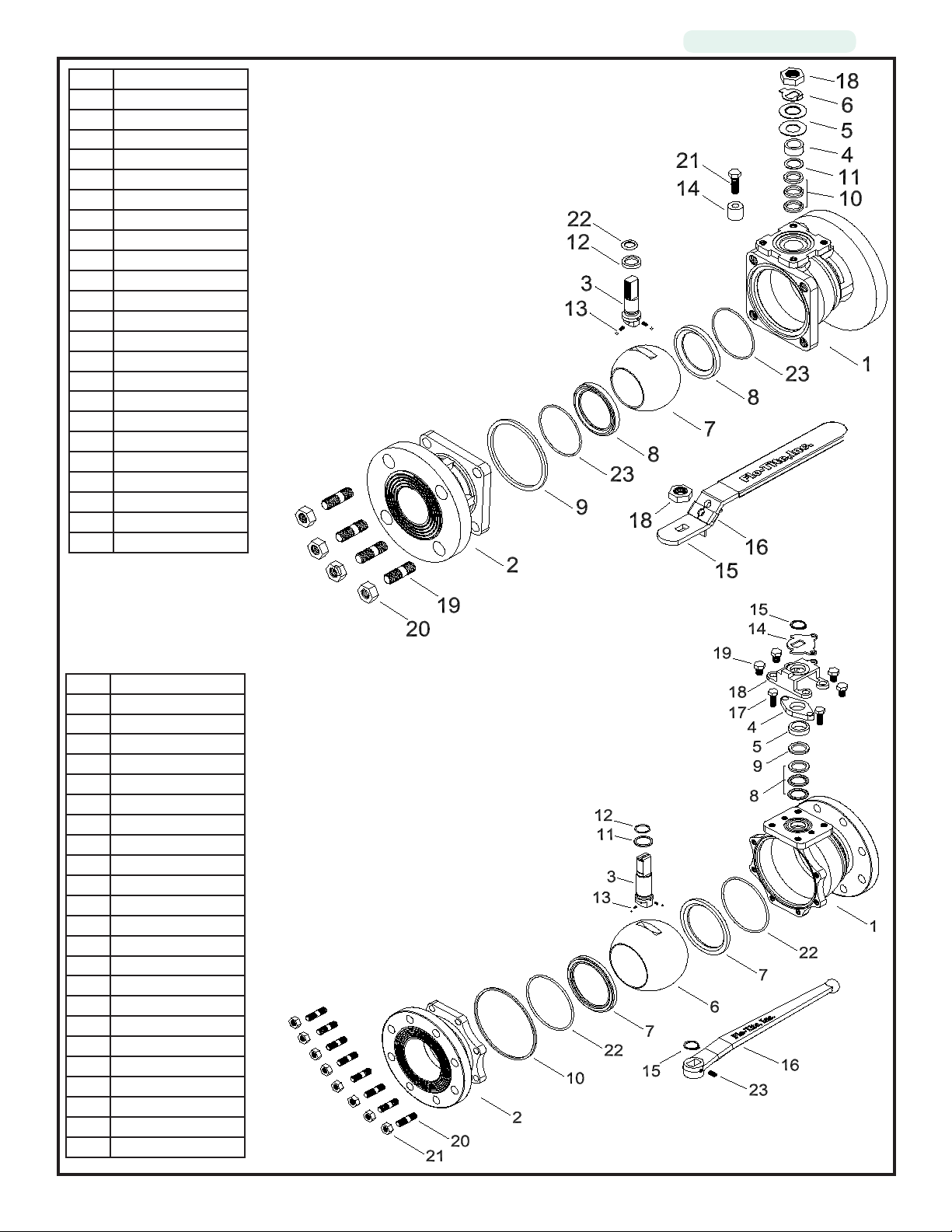
1/2” - 2”
Valve Component
2.5” - 12”
Valve Component
No. Part List
1 Body
2 End Cap
3 Stem
4 Packing Follower
5 Belleville Washer
6 Locker Washer
7 Ball
8 Seat
9 Gasket
10 Stem Packing
11 Packing Protector
12 Thrust Washer
13 Anti-Static
14 Valve Stop
15 Handle
16 Locking Device
17 Handle Sleeve
18 Thin Nut
19 Body Stud
20 Body Nut
21 Bolt
22 O-Ring
23 Seat O-Ring
No. Part List
1 Body
2 End Cap
3 Stem
4 Packing Gland
5 Packing Follower
6 Ball
7 Seat
8 Stem Packing
9 Packing Protector
10 Gasket
11 Thrust Washer
12 O-Ring
13 Anti-Static
14 Travel Stop
15 Snap Ring
16 Handle
17 Gland Bolt
18 Stop Housing
19 Housing Bolt
20 Body Stud
21 Body Nut
22 O-Ring
23 Set Screw
This manual suits for next models
2
Table of contents
Other Flo-Tite Control Unit manuals


Popular Control Unit manuals by other brands


Shinko
Shinko NCL-13A instruction manual

National Instruments
National Instruments 6589 Getting started guide

Pfeiffer Vacuum
Pfeiffer Vacuum DVB 016 PX operating instructions

TLV
TLV PowerDyne QuickTrap P46UC instruction manual

Rockwell Automation
Rockwell Automation AB quality Allen-Bradley 1746-INT4 user manual

LPRS
LPRS ERA900TRS user guide