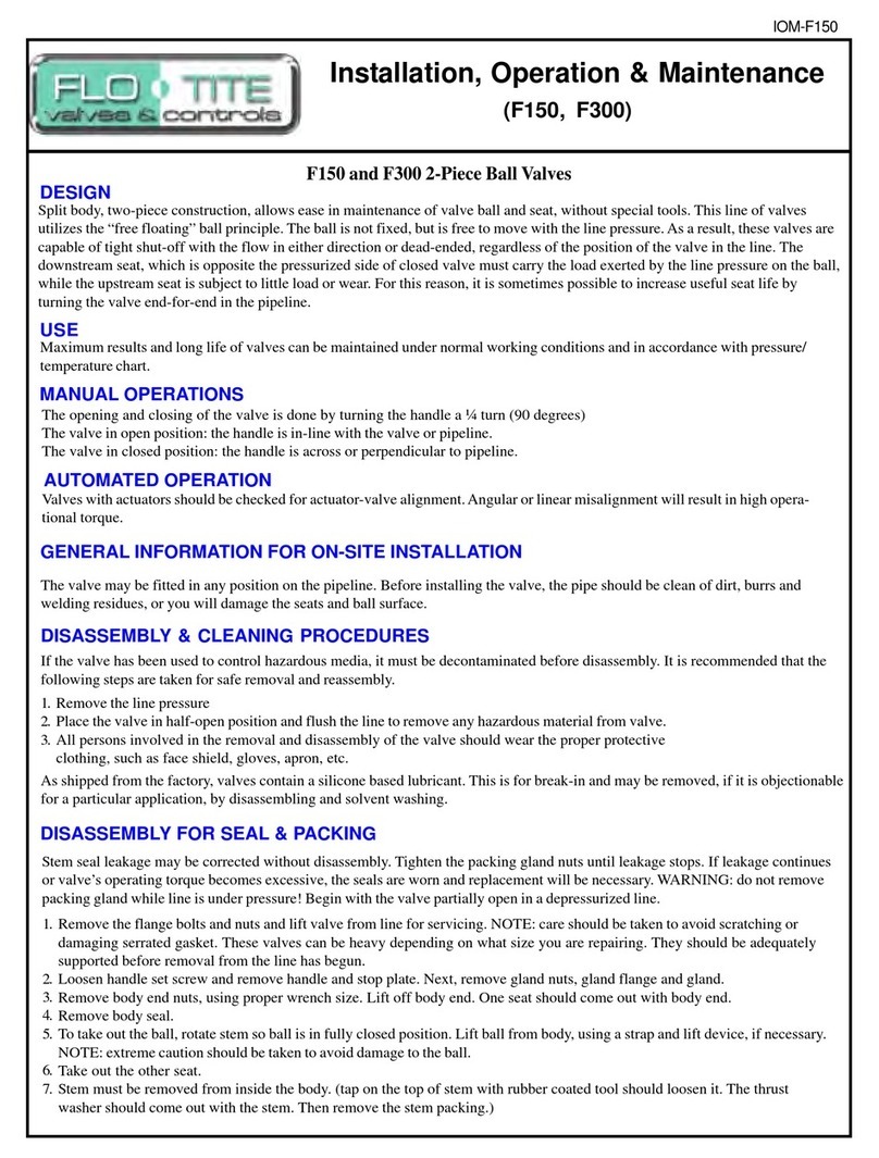
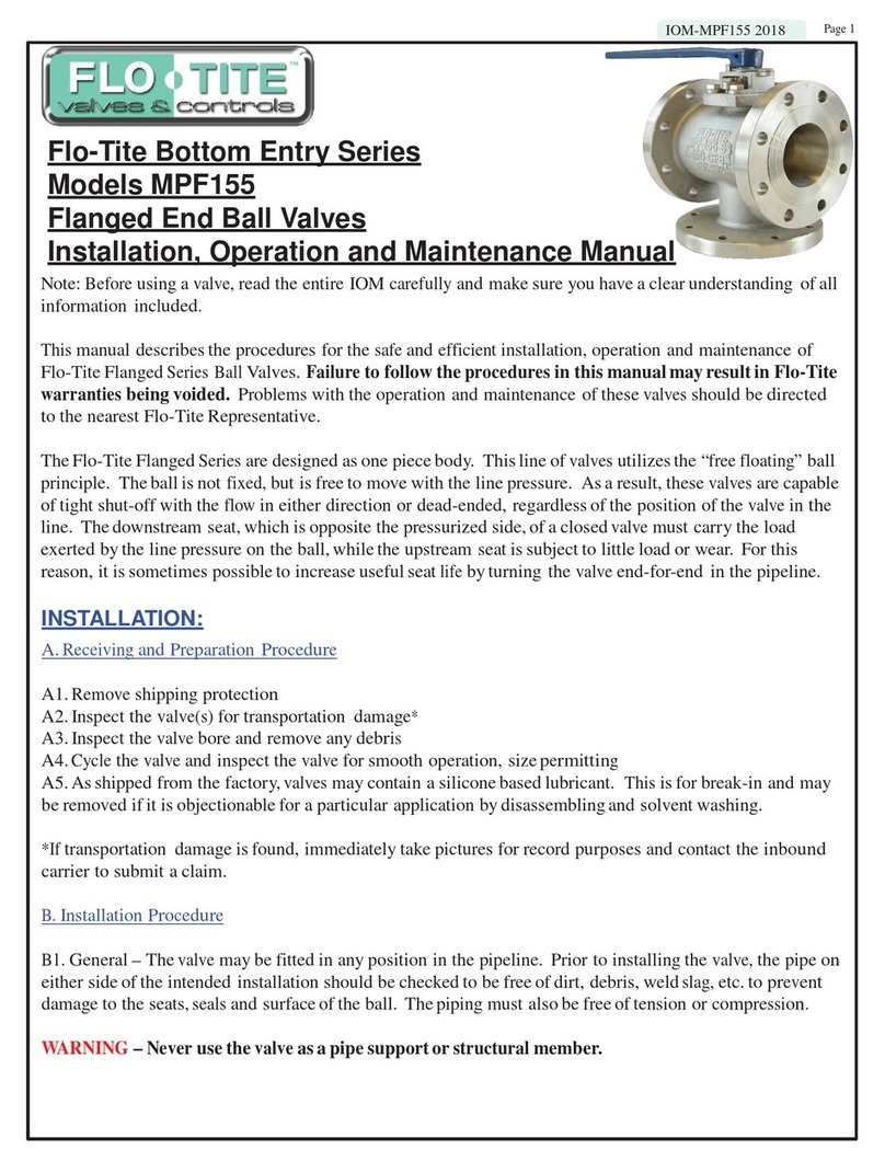
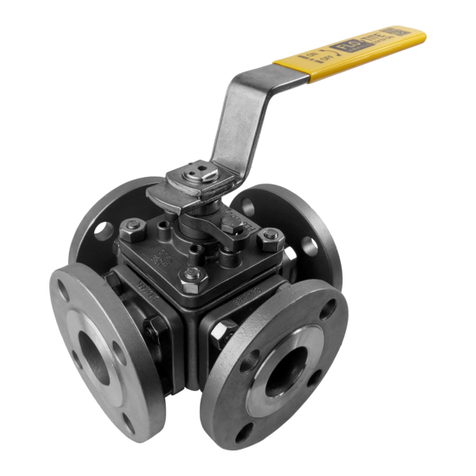
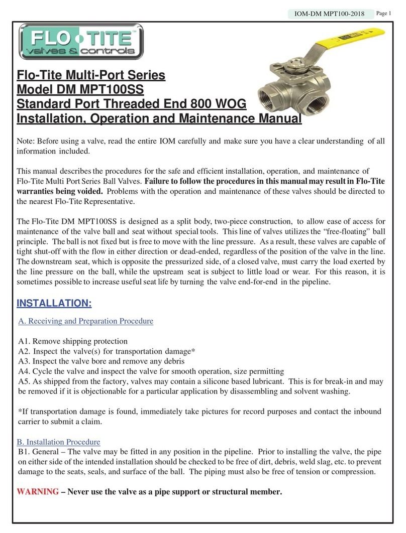
Flo-Tite SV Series User manual

22-22 IOM-SV /SV-2022 Page 1
Flo-Tite SV Series Solenoid Valves
Models SV / S4 / S4-2
Installation, Operation and Maintenance Manual
Those solenoid spool valves are designed to operate with filtered (<=40µm), dry or lubricated air or neutral
gas and within the technical characteristics specified on the nameplate and the Data Sheet.
PNEUMATIC CONNECTION:
General Recommendations
Connect pipers for the required functions in accordance with this documentation and the ports markings on
the product. Make sure that no foreign matter enters the system. Correctly support and align pipes to prevent
mechanical strain on the valve.
When tightening, do no use the valve as a lever. Locate wrenches as close as possible to connection point. To
avoid damage to the equipment, DO NOT OVER TIGHTEN pipe connections.
Connection of the Spool Valve
SV series serves exclusively as a 3/2, 5/2 or 5/3 solenoid valve. Pressure inlet at port 1 on the body of the
valve. Pressure outlet at port 2 and 4 on the body or on the interface plates. Exhaust at ports 3 and 5 on the
body of the valve. Technical details please consult with Dimension and Installing.
Connection of Pilot Exhaust
The standard model has a 03 exhaust port at end of the pilot valve. Just fixing and tightening a M8x0.75
female nut supplied on it.
MANUAL OVERRIDE OPERATION:
ELECTRICAL CONNECTION:
General Recommendation
• Electrical connection must be made by qualified personnel and according to
applicable local standards and regulations.
• Before any electrical connection, turn off the electrical current to power off the
components.
• Depending on the voltage, electrical components must be grounded according
to local standards and regulations.
• Most valves are designed to continuous duty, To prevent the risk of personal
injury, do not touch operating condition.
• Standard coils (C0)
Electrical connection is made with detachable plug connector for cable dia.
6-8mm (see fig.), rotatable by 180 increments (3 pins: 1, 2 electric pins+PE)
ELECTRICAL CONNECTION (CONTINUED):
• Flameproof coils (C4, C5)
Electrical connection is made with wiring box with M20-1.5 or 1/2” cable entry, two points terminal strip
for electric pins + ground pins and outside ground pins is available (see fig.).
• Other explosion proof coils
See particular data sheet delivered with these coils.
MAINTENANCE:
CAUTION - Prior to any maintenance work, switch off power supply, depressurize and vent the valve to
prevent the risk of personal injury or damage equipment.
Preventive Maintenance
Operate the valve at least once a month to check its function.
Avoid obstruction of exhaust port when it is not connected or protect it with a cap.
Cleaning
Maintenance of the valve depends on the operating conditions. They must be cleaned at regular intervals.
Cleaning must be done when a slowing down of the cycle, a leakage or an abnormal noise is noticed. The
components must be checked for excessive wear. Cleaning must be made with suitable solvent.
Spare Parts
After a prolonged use, it can be necessary to replace the active components of the valve. A Spare Parts Kit is
available for each version of spool valve. Contact the manufacturer or his representative.
Flameproof Joints
Repairs of the flameproof joints must be in compliance with the structural specifications provided by the
manufacturer. Repairs must not be made on the basis of values specified in tables 2 and 3 of EN.IEC
60079-1.
Troubleshooting
Note: Before using a valve, read the entire IOM carefully and make sure you have a clear understanding of all
Information included.
This manual describes the procedures for the safe and efficient installation, operation, and maintenance of
Flo-Tite's SV Series Solenoid Valves. Failure to follow the procedures of this manual may result in the
Flo-Tite warrantybeing voided. Problems with the operation and maintenance of these valves should be
directed to the nearest Flo-Tite Representative.
The SV Series solenoid operated spool valve is made of anodized aluminum or stainless steel. The spool
valves have threaded port connectionsand/or Namur interface. In the below form, you can find the basic
pneumatic data for every member of the SV Series Spool valve.
The SV Series direct operated valves are suitable for single (mono-stable) solenoidswith standard coils, and
various explosion-proof coils certified for use in hazardous areas(Zone 0, 1, 2 and Class I Div. 1&2 Groups
A, B, C and D)
SV Series Pilot operated spool valve is suitable for single/dual (mono/bi-stable) solenoid standard coils,
Cnomo interface coils or various explosion-proof coils certified for use in hazardous areas(Zone 0, 1, 2 and
Class I Div. 1&2 Group A, B, C and D)
As for S4/S4-2 Series Namur version , the 5/2 function spool valves are available to be mounted directly for
controlling double-acting actuatorsand the same spool valve also can be adapted by 3/2NC Namur function
interface plate for controlling single-acting actuators.
As for S4/S4-2 Series Namur version, the same spool valve can be adapted by 5/2 or 3/2 NC function Namur
interface plates for controlling double-acting or single-acting actuators.
SPECIAL CONDITIONS FOR SAFE USE:
To ensure the proper function of the device and promote a long service life, you must comply with the
information in these Operation Instructions and the application conditions and specifications provided in the
Data Sheet. Usage of the device in a manner that is contrary to theOperating Instructions or the application
condition and specification provided in the Data Sheet is improper and will void your warranty. This device
serves exclusively as a 3/2, 5/2 or 5/3 solenoid valve for the media stated to be permissible on this Introduc-
tion and Data Sheet. Any other use is considered to be improper use. The manufacturer will not be responsi-
ble for any improper use of the device.
Changes to the product may only be the made after consulting the manufacturer or his representative. Instal-
lation and maintenance of the valve must be carried out by qualified personnel only.
DIMENSION AND INSTALLING:
CAUTION - Prior installing the solenoid valve, depressurize the pipes and clean them internally to avoid
particles entering the system (tape sealant, thread compound). The valve may be mounted on the Namur
interface of the pneumatic actuator in usage of Namur interface plates depending on the design of the spool
valve.
DIMENSION AND INSTALLING (CONTINUED):
The mounting dimensions of the SV series directing solenoid valve is multi-mount design. For the same
body, the Namur and threaded connections are available. As for Namur connection, the body can be directly
mounted to the Namur interface of the pneumatic actuator with two screws M5x35 (Torque 4-5Nm) provid-
ed. Details see the below Fig.
The mounting dimensions of the S4/S4-2 series pilot solenoid valve is directly Namur connection design
(threaded connection available). For 5/2 function, the spool valve can be directly mounted to the Namur
interface of the pneumatic actuator with two screws M5x27 for S4 and M6x35 for S4-2 (Torque 4-5Nm)
provided. For 3/2 NC function, armed with 3/2 Namur interface plate provided, the spool valve can be
mounted to the Namur interface of the pneumatic actuator with two screws M5x35 of S4 and M6x55 for
S4-2 (torque 4-5Nm) provided. Details see the below Fig.
The mounting dimension design of the S4/S4-SS series pilot solenoid valve is exactly in light of Namur
standard (threaded connection available). The same spool valve equips with 3/2 and 5/2 function. Namur
interface plates provided for controlling single-acting and double-acting actuators. According to the direction
f the Namur interface plates, fix the spool valve and the interface plat on the namur interface of the pneumat-
ic actuator with two screws M5x35 (Torque 4-5Nm) provided. Details see the below fig.

This manual describes the procedures for the safe and efficient installation, operation, and maintenance of
Flo-Tite SV Series Solenoid Valves. Failure to follow the procedures of this manual may result in
Flo-Tite warranties being voided. Problems with the operation and maintenance of these valves should be
directed to the nearest Flo-Tite Representative.
SV series solenoid operated spool valve made of anodized aluminum or stainless steel. The spool valves have
threaded port connection and/or Namur interface. In below form, you can find the basic pneumatic data for
every member of SV series spool valve.
SV series direct operated valves is suitable for single (mono-stable) solenoid with standard coils, and various
explosion-proof coils certified for use in hazardous area (Zone 0, 1, 2 and Class I Div. 1&2 Groups A, B, C
and D)
SV series pilot operated spool valve is suitable for single/dual (mono/bi-stable) solenoid standard coils,
Cnomo interface coils or various explosion-proof coils certified for use in hazardous area (Zone 0, 1, 2 and
Class I Div. 1&2 Group A, B, C and D)
As for S4/S4-2 series Namur version , the 5/2 function spool valves are available to be mounted directly for
controlling double-acting actuator and the same spool valve also can be adapted by 3/2NC Namur function
interface plate for controlling single-acting actuators.
As for S4/S4-2 series Namur version, the same spool valve can be adapted by 5/2 or 3/2 NC function Namur
interface plates for controlling double-acting or single-acting actuators.
SPECIAL CONDITIONS FOR SAFE USE:
To ensure the proper function of the device and promote long service life, you must comply with the informa-
tion in these Operation Instructions and the application conditions and specifications provided in the Data
Sheet. Usage of the device in a manner that is contrary to those Operating Instructions or the application
condition and specification provided in the Data Sheet is improper and will void your warranty. This device
serves exclusively as a 3/2, 5/2 or 5/3 solenoid valve for the media stated to be permissible on this Introduc-
tion and Data Sheet. Any other use is considered to be improper use. The manufacturer will not be responsi-
ble for any improper use of the device.
Changes to the product may only be the made after consulting the manufacturer or his representative. Instal-
lation and maintenance of the valve must be carried out by qualified personnel only.
Those solenoid spool valves are designed to operate with filtered (<=40µm), dry or lubricated air or neutral
gas and within the technical characteristics specified on the nameplate and the Data Sheet.
PNEUMATIC CONNECTION:
General Recommendations
Connect pipers for the required functions in accordance with this documentation and the port markings on
the product. Make sure that no foreign matter enters the system. Correctly support and align pipes to prevent
mechanical strain on the valve.
When tightening, do no use the valve as a lever. Locate wrenches as close as possible to connection point. To
avoid damage to the equipment, DO NOT OVER TIGHTEN pipe connections.
Connection of the Spool Valve
The SV Series serves exclusively as a 3/2, 5/2 or 5/3 solenoid valve.
Pressure inlet at port 1 on the body of
the valve. Pressure outlet at port 2 and 4 on the body or on the interface plates. Exhaust at ports 3 and 5 on
the body of the valve.
For technical details, please consult the factory or a Flo-Tite representative.
Connection of Pilot Exhaust
The standard model has a 03 exhaust port at the end of the pilot valve. Just attach and tighten a M8x0.75
female nut supplied on it.
MANUAL OVERRIDE OPERATION:
ELECTRICAL CONNECTION:
General Recommendation
• Electrical connection must be made by qualified personnel and according to
applicable local standards and regulations.
• Before any electrical connection, turn off the electrical current to power off the
components.
• Depending on the voltage, electrical components must be grounded according
to local standards and regulations.
• Most valves are designed to continuous duty, To prevent the risk of personal
injury, do not touch operating condition.
• Standard coils (C0)
Electrical connection is made with detachable plug connector for cable dia.
6-8mm (see fig.), rotatable by 180 increments (3 pins: 1, 2 electric pins+PE)
ELECTRICAL CONNECTION (CONTINUED):
• Flameproof coils (C4, C5)
Electrical connection is made with wiring box with M20-1.5 or 1/2” cable entry, two points terminal strip
for electric pins + ground pins and outside ground pins is available (see fig.).
• Other explosion proof coils
See particular data sheet delivered with these coils.
MAINTENANCE:
CAUTION - Prior to any maintenance work, switch off power supply, depressurize and vent the valve to
prevent the risk of personal injury or damage equipment.
Preventive Maintenance
Operate the valve at least once a month to check its function.
Avoid obstruction of exhaust port when it is not connected or protect it with a cap.
Cleaning
Maintenance of the valve depends on the operating conditions. They must be cleaned at regular intervals.
Cleaning must be done when a slowing down of the cycle, a leakage or an abnormal noise is noticed. The
components must be checked for excessive wear. Cleaning must be made with suitable solvent.
Spare Parts
After a prolonged use, it can be necessary to replace the active components of the valve. A Spare Parts Kit is
available for each version of spool valve. Contact the manufacturer or his representative.
Flameproof Joints
Repairs of the flameproof joints must be in compliance with the structural specifications provided by the
manufacturer. Repairs must not be made on the basis of values specified in tables 2 and 3 of EN.IEC
60079-1.
Troubleshooting
22-22 IOM-SV /SV-2022 Page 2
For S4/S4-2
Press the button of override, turn left, switch the override
into horizontal position with the body into manual status.
Vertical in Auto status,
horizontal in Manual status
This means the solenoid
valve is in Manual Status
This means the solenoid
valve is in Manual Status
This means the solenoid
valve is in Auto Status
This means the solenoid
valve is in Auto Status
For S4
1 stands for Manual, 0 stands for Auto-Switch.
To override , turn clockwise to turn the solenoid
valve from Auto status to Manual status.
DIMENSION AND INSTALLING:
CAUTION - Prior installing the solenoid valve, depressurize the pipes and clean them internally to avoid
particles entering the system (tape sealant, thread compound). The valve may be mounted on the Namur
interface of the pneumatic actuator in usage of Namur interface plates depending on the design of the spool
valve.
DIMENSION AND INSTALLING (CONTINUED):
The mounting dimensions of the SV series directing solenoid valve is multi-mount design. For the same
body, the Namur and threaded connections are available. As for Namur connection, the body can be directly
mounted to the Namur interface of the pneumatic actuator with two screws M5x35 (Torque 4-5Nm) provid-
ed. Details see the below Fig.
The mounting dimensions of the S4/S4-2 series pilot solenoid valve is directly Namur connection design
(threaded connection available). For 5/2 function, the spool valve can be directly mounted to the Namur
interface of the pneumatic actuator with two screws M5x27 for S4 and M6x35 for S4-2 (Torque 4-5Nm)
provided. For 3/2 NC function, armed with 3/2 Namur interface plate provided, the spool valve can be
mounted to the Namur interface of the pneumatic actuator with two screws M5x35 of S4 and M6x55 for
S4-2 (torque 4-5Nm) provided. Details see the below Fig.
The mounting dimension design of the S4/S4-SS series pilot solenoid valve is exactly in light of Namur
standard (threaded connection available). The same spool valve equips with 3/2 and 5/2 function. Namur
interface plates provided for controlling single-acting and double-acting actuators. According to the direction
f the Namur interface plates, fix the spool valve and the interface plat on the namur interface of the pneumat-
ic actuator with two screws M5x35 (Torque 4-5Nm) provided. Details see the below fig.

This manual describes the procedures for the safe and efficient installation, operation, and maintenance of
Flo-Tite SV Series Solenoid Valves. Failure to follow the procedures of this manual may result in
Flo-Tite warranties being voided. Problems with the operation and maintenance of these valves should be
directed to the nearest Flo-Tite Representative.
SV series solenoid operated spool valve made of anodized aluminum or stainless steel. The spool valves have
threaded port connection and/or Namur interface. In below form, you can find the basic pneumatic data for
every member of SV series spool valve.
SV series direct operated valves is suitable for single (mono-stable) solenoid with standard coils, and various
explosion-proof coils certified for use in hazardous area (Zone 0, 1, 2 and Class I Div. 1&2 Groups A, B, C
and D)
SV series pilot operated spool valve is suitable for single/dual (mono/bi-stable) solenoid standard coils,
Cnomo interface coils or various explosion-proof coils certified for use in hazardous area (Zone 0, 1, 2 and
Class I Div. 1&2 Group A, B, C and D)
As for S4/S4-2 series Namur version , the 5/2 function spool valves are available to be mounted directly for
controlling double-acting actuator and the same spool valve also can be adapted by 3/2NC Namur function
interface plate for controlling single-acting actuators.
As for S4/S4-2 series Namur version, the same spool valve can be adapted by 5/2 or 3/2 NC function Namur
interface plates for controlling double-acting or single-acting actuators.
SPECIAL CONDITIONS FOR SAFE USE:
To ensure the proper function of the device and promote long service life, you must comply with the informa-
tion in these Operation Instructions and the application conditions and specifications provided in the Data
Sheet. Usage of the device in a manner that is contrary to those Operating Instructions or the application
condition and specification provided in the Data Sheet is improper and will void your warranty. This device
serves exclusively as a 3/2, 5/2 or 5/3 solenoid valve for the media stated to be permissible on this Introduc-
tion and Data Sheet. Any other use is considered to be improper use. The manufacturer will not be responsi-
ble for any improper use of the device.
Changes to the product may only be the made after consulting the manufacturer or his representative. Instal-
lation and maintenance of the valve must be carried out by qualified personnel only.
Those solenoid spool valves are designed to operate with filtered (<=40µm), dry or lubricated air or neutral
gas and within the technical characteristics specified on the nameplate and the Data Sheet.
PNEUMATIC CONNECTION:
General Recommendations
Connect pipers for the required functions in accordance with this documentation and the ports markings on
the product. Make sure that no foreign matter enters the system. Correctly support and align pipes to prevent
mechanical strain on the valve.
When tightening, do no use the valve as a lever. Locate wrenches as close as possible to connection point. To
avoid damage to the equipment, DO NOT OVER TIGHTEN pipe connections.
Connection of the Spool Valve
SV series serves exclusively as a 3/2, 5/2 or 5/3 solenoid valve. Pressure inlet at port 1 on the body of the
valve. Pressure outlet at port 2 and 4 on the body or on the interface plates. Exhaust at ports 3 and 5 on the
body of the valve. Technical details please consult with Dimension and Installing.
Connection of Pilot Exhaust
The standard model has a 03 exhaust port at end of the pilot valve. Just fixing and tightening a M8x0.75
female nut supplied on it.
MANUAL OVERRIDE OPERATION:
ELECTRICAL CONNECTION:
General Recommendation
• Electrical connection must be made by qualified personnel and according to
applicable local standards and regulations.
• Before any electrical connection, turn off the electrical current to power off the
components.
• Depending on the voltage, electrical components must be grounded according
to local standards and regulations.
• Most valves are designed to continuous duty, To prevent the risk of personal
injury, do not touch operating condition.
• Standard coils (C0)
Electrical connection is made with detachable plug connector for cable dia.
6-8mm (see fig.), rotatable by 180 increments (3 pins: 1, 2 electric pins+PE)
ELECTRICAL CONNECTION (CONTINUED):
• Flameproof coils (C4, C5)
Electrical connection is made with wiring box with M20-1.5 or 1/2” cable entry, two points terminal strip
for electric pins + ground pins and outside ground pins is available (see fig.).
• Other explosion proof coils
See particular data sheet delivered with these coils.
MAINTENANCE:
CAUTION - Prior to any maintenance work, switch off power supply, depressurize and vent the valve to
prevent the risk of personal injury or damage equipment.
Preventive Maintenance
Operate the valve at least once a month to check its function.
Avoid obstruction of exhaust port when it is not connected or protect it with a cap.
Cleaning
Maintenance of the valve depends on the operating conditions. They must be cleaned at regular intervals.
Cleaning must be done when a slowing down of the cycle, a leakage or an abnormal noise is noticed. The
components must be checked for excessive wear. Cleaning must be done with suitable solvent.
Spare Parts
After a prolonged use, it may be necessary to replace the active components of the valve. A Spare Parts Kit
is available for each version of the spool valve. Contact the manufacturer or arepresentative.
Flameproof Joints
Repairs of the flameproof joints must be in compliance with the structural specifications provided by the
manufacturer. Repairs must not be made on the basis of values specified in tables 2 and 3 of EN.IEC
60079-1.
Troubleshooting
22-22 IOM-SV /SV-2022 Page 3
Valve fails to operate
(no switching noise)
- Check the electrical supply complies with values mentioned on the
nameplate or coil.
- Check coil for shorts or damage
- Check that mobile parts (spool, pilot plunger) are not blocked by
foreign particles
- Check to see the Namur interface plate is mounted incorrectly
Valve fails to return
(for mono-stable)
-Check if the return spring is broken
-Check if the pilot exhaust port is blocked
Valve switches but without effect -Verify connectors and tightening of the valve on its interface plate
-Verify if the pilot plunger is broken
External leakage -Verify connectors and tightening of the valve on its interface plate
-Verify the tightening of the pilot
DIMENSION AND INSTALLING:
CAUTION - Prior to installing the solenoid valve, depressurize the pipes and clean them internally to
avoid particles entering the system (tape sealant, thread compound). The valve may be mounted on the
Namur interface of the pneumatic actuator in usage of Namur interface plates depending on the design of
the spool valve.
DIMENSION AND INSTALLING (CONTINUED):
The mounting dimensions of the SV series directing solenoid valve is multi-mount design. For the same
body, the Namur and threaded connections are available. As for Namur connection, the body can be directly
mounted to the Namur interface of the pneumatic actuator with two screws M5x35 (Torque 4-5Nm) provid-
ed. Details see the below Fig.
The mounting dimensions of the S4/S4-2 series pilot solenoid valve is directly Namur connection design
(threaded connection available). For 5/2 function, the spool valve can be directly mounted to the Namur
interface of the pneumatic actuator with two screws M5x27 for S4 and M6x35 for S4-2 (Torque 4-5Nm)
provided. For 3/2 NC function, armed with 3/2 Namur interface plate provided, the spool valve can be
mounted to the Namur interface of the pneumatic actuator with two screws M5x35 of S4 and M6x55 for
S4-2 (torque 4-5Nm) provided. Details see the below Fig.
The mounting dimension design of the S4/S4-SS series pilot solenoid valve is exactly in light of Namur
standard (threaded connection available). The same spool valve equips with 3/2 and 5/2 function. Namur
interface plates provided for controlling single-acting and double-acting actuators. According to the direction
f the Namur interface plates, fix the spool valve and the interface plat on the namur interface of the pneumat-
ic actuator with two screws M5x35 (Torque 4-5Nm) provided. Details see the below fig.

This manual describes the procedures for the safe and efficient installation, operation, and maintenance of
Flo-Tite SV Series Solenoid Valves. Failure to follow the procedures of this manual may result in
Flo-Tite warranties being voided. Problems with the operation and maintenance of these valves should be
directed to the nearest Flo-Tite Representative.
SV series solenoid operated spool valve made of anodized aluminum or stainless steel. The spool valves have
threaded port connection and/or Namur interface. In below form, you can find the basic pneumatic data for
every member of SV series spool valve.
SV series direct operated valves is suitable for single (mono-stable) solenoid with standard coils, and various
explosion-proof coils certified for use in hazardous area (Zone 0, 1, 2 and Class I Div. 1&2 Groups A, B, C
and D)
SV series pilot operated spool valve is suitable for single/dual (mono/bi-stable) solenoid standard coils,
Cnomo interface coils or various explosion-proof coils certified for use in hazardous area (Zone 0, 1, 2 and
Class I Div. 1&2 Group A, B, C and D)
As for S4/S4-2 series Namur version , the 5/2 function spool valves are available to be mounted directly for
controlling double-acting actuator and the same spool valve also can be adapted by 3/2NC Namur function
interface plate for controlling single-acting actuators.
As for S4/S4-2 series Namur version, the same spool valve can be adapted by 5/2 or 3/2 NC function Namur
interface plates for controlling double-acting or single-acting actuators.
SPECIAL CONDITIONS FOR SAFE USE:
To ensure the proper function of the device and promote long service life, you must comply with the informa-
tion in these Operation Instructions and the application conditions and specifications provided in the Data
Sheet. Usage of the device in a manner that is contrary to those Operating Instructions or the application
condition and specification provided in the Data Sheet is improper and will void your warranty. This device
serves exclusively as a 3/2, 5/2 or 5/3 solenoid valve for the media stated to be permissible on this Introduc-
tion and Data Sheet. Any other use is considered to be improper use. The manufacturer will not be responsi-
ble for any improper use of the device.
Changes to the product may only be the made after consulting the manufacturer or his representative. Instal-
lation and maintenance of the valve must be carried out by qualified personnel only.
Those solenoid spool valves are designed to operate with filtered (<=40µm), dry or lubricated air or neutral
gas and within the technical characteristics specified on the nameplate and the Data Sheet.
PNEUMATIC CONNECTION:
General Recommendations
Connect pipers for the required functions in accordance with this documentation and the ports markings on
the product. Make sure that no foreign matter enters the system. Correctly support and align pipes to prevent
mechanical strain on the valve.
When tightening, do no use the valve as a lever. Locate wrenches as close as possible to connection point. To
avoid damage to the equipment, DO NOT OVER TIGHTEN pipe connections.
Connection of the Spool Valve
SV series serves exclusively as a 3/2, 5/2 or 5/3 solenoid valve. Pressure inlet at port 1 on the body of the
valve. Pressure outlet at port 2 and 4 on the body or on the interface plates. Exhaust at ports 3 and 5 on the
body of the valve. Technical details please consult with Dimension and Installing.
Connection of Pilot Exhaust
The standard model has a 03 exhaust port at end of the pilot valve. Just fixing and tightening a M8x0.75
female nut supplied on it.
MANUAL OVERRIDE OPERATION:
ELECTRICAL CONNECTION:
General Recommendation
• Electrical connection must be made by qualified personnel and according to
applicable local standards and regulations.
• Before any electrical connection, turn off the electrical current to power off the
components.
• Depending on the voltage, electrical components must be grounded according
to local standards and regulations.
• Most valves are designed to continuous duty, To prevent the risk of personal
injury, do not touch operating condition.
• Standard coils (C0)
Electrical connection is made with detachable plug connector for cable dia.
6-8mm (see fig.), rotatable by 180 increments (3 pins: 1, 2 electric pins+PE)
ELECTRICAL CONNECTION (CONTINUED):
• Flameproof coils (C4, C5)
Electrical connection is made with wiring box with M20-1.5 or 1/2” cable entry, two points terminal strip
for electric pins + ground pins and outside ground pins is available (see fig.).
• Other explosion proof coils
See particular data sheet delivered with these coils.
MAINTENANCE:
CAUTION - Prior to any maintenance work, switch off power supply, depressurize and vent the valve to
prevent the risk of personal injury or damage equipment.
Preventive Maintenance
Operate the valve at least once a month to check its function.
Avoid obstruction of exhaust port when it is not connected or protect it with a cap.
Cleaning
Maintenance of the valve depends on the operating conditions. They must be cleaned at regular intervals.
Cleaning must be done when a slowing down of the cycle, a leakage or an abnormal noise is noticed. The
components must be checked for excessive wear. Cleaning must be made with suitable solvent.
Spare Parts
After a prolonged use, it can be necessary to replace the active components of the valve. A Spare Parts Kit is
available for each version of spool valve. Contact the manufacturer or his representative.
Flameproof Joints
Repairs of the flameproof joints must be in compliance with the structural specifications provided by the
manufacturer. Repairs must not be made on the basis of values specified in tables 2 and 3 of EN.IEC
60079-1.
Troubleshooting
DIMENSION AND INSTALLING:
CAUTION - Prior installing the solenoid valve, depressurize the pipes and clean them internally to avoid
particles entering the system (tape sealant, thread compound). The valve may be mounted on the Namur
interface of the pneumatic actuator in usage of Namur interface plates depending on the design of the spool
valve.
DIMENSION AND INSTALLING (CONTINUED):
The mounting dimensions of the SV Series directing solenoid valve is multi-mount designed. For the same
body, the Namur and threaded connections are available. As for the Namur connection, the body can be
directly mounted to the Namur interface of the pneumatic actuator with two screws M5x35 (Torque
4-5Nm) provided. Details see the below Figures.
The mounting dimensions of the S4/S4-2 series pilot solenoid valve is directly Namur connection design
(threaded connection available). For 5/2 function, the spool valve can be directly mounted to the Namur
interface of the pneumatic actuator with two screws M5x27 for S4 and M6x35 for S4-2 (Torque 4-5Nm)
provided. For 3/2 NC function, armed with 3/2 Namur interface plate provided, the spool valve can be
mounted to the Namur interface of the pneumatic actuator with two screws M5x35 of S4 and M6x55 for
S4-2 (torque 4-5Nm) provided. Details see the below Figure.
22-22 IOM-SV /SV-2022 Page 4
The mounting dimension design of the S4/S4-SS series pilot solenoid valve is exactly in light of Namur
standard (threaded connection available). The same spool valve equips with 3/2 and 5/2 function. Namur
interface plates provided for controlling single-acting and double-acting actuators. According to the direction
f the Namur interface plates, fix the spool valve and the interface plat on the namur interface of the pneumat-
ic actuator with two screws M5x35 (Torque 4-5Nm) provided. Details see the below fig.

This manual describes the procedures for the safe and efficient installation, operation, and maintenance of
Flo-Tite SV Series Solenoid Valves. Failure to follow the procedures of this manual may result in
Flo-Tite warranties being voided. Problems with the operation and maintenance of these valves should be
directed to the nearest Flo-Tite Representative.
SV series solenoid operated spool valve made of anodized aluminum or stainless steel. The spool valves have
threaded port connection and/or Namur interface. In below form, you can find the basic pneumatic data for
every member of SV series spool valve.
SV series direct operated valves is suitable for single (mono-stable) solenoid with standard coils, and various
explosion-proof coils certified for use in hazardous area (Zone 0, 1, 2 and Class I Div. 1&2 Groups A, B, C
and D)
SV series pilot operated spool valve is suitable for single/dual (mono/bi-stable) solenoid standard coils,
Cnomo interface coils or various explosion-proof coils certified for use in hazardous area (Zone 0, 1, 2 and
Class I Div. 1&2 Group A, B, C and D)
As for S4/S4-2 series Namur version , the 5/2 function spool valves are available to be mounted directly for
controlling double-acting actuator and the same spool valve also can be adapted by 3/2NC Namur function
interface plate for controlling single-acting actuators.
As for S4/S4-2 series Namur version, the same spool valve can be adapted by 5/2 or 3/2 NC function Namur
interface plates for controlling double-acting or single-acting actuators.
SPECIAL CONDITIONS FOR SAFE USE:
To ensure the proper function of the device and promote long service life, you must comply with the informa-
tion in these Operation Instructions and the application conditions and specifications provided in the Data
Sheet. Usage of the device in a manner that is contrary to those Operating Instructions or the application
condition and specification provided in the Data Sheet is improper and will void your warranty. This device
serves exclusively as a 3/2, 5/2 or 5/3 solenoid valve for the media stated to be permissible on this Introduc-
tion and Data Sheet. Any other use is considered to be improper use. The manufacturer will not be responsi-
ble for any improper use of the device.
Changes to the product may only be the made after consulting the manufacturer or his representative. Instal-
lation and maintenance of the valve must be carried out by qualified personnel only.
Those solenoid spool valves are designed to operate with filtered (<=40µm), dry or lubricated air or neutral
gas and within the technical characteristics specified on the nameplate and the Data Sheet.
PNEUMATIC CONNECTION:
General Recommendations
Connect pipers for the required functions in accordance with this documentation and the ports markings on
the product. Make sure that no foreign matter enters the system. Correctly support and align pipes to prevent
mechanical strain on the valve.
When tightening, do no use the valve as a lever. Locate wrenches as close as possible to connection point. To
avoid damage to the equipment, DO NOT OVER TIGHTEN pipe connections.
Connection of the Spool Valve
SV series serves exclusively as a 3/2, 5/2 or 5/3 solenoid valve. Pressure inlet at port 1 on the body of the
valve. Pressure outlet at port 2 and 4 on the body or on the interface plates. Exhaust at ports 3 and 5 on the
body of the valve. Technical details please consult with Dimension and Installing.
Connection of Pilot Exhaust
The standard model has a 03 exhaust port at end of the pilot valve. Just fixing and tightening a M8x0.75
female nut supplied on it.
MANUAL OVERRIDE OPERATION:
ELECTRICAL CONNECTION:
General Recommendation
• Electrical connection must be made by qualified personnel and according to
applicable local standards and regulations.
• Before any electrical connection, turn off the electrical current to power off the
components.
• Depending on the voltage, electrical components must be grounded according
to local standards and regulations.
• Most valves are designed to continuous duty, To prevent the risk of personal
injury, do not touch operating condition.
• Standard coils (C0)
Electrical connection is made with detachable plug connector for cable dia.
6-8mm (see fig.), rotatable by 180 increments (3 pins: 1, 2 electric pins+PE)
ELECTRICAL CONNECTION (CONTINUED):
• Flameproof coils (C4, C5)
Electrical connection is made with wiring box with M20-1.5 or 1/2” cable entry, two points terminal strip
for electric pins + ground pins and outside ground pins is available (see fig.).
• Other explosion proof coils
See particular data sheet delivered with these coils.
MAINTENANCE:
CAUTION - Prior to any maintenance work, switch off power supply, depressurize and vent the valve to
prevent the risk of personal injury or damage equipment.
Preventive Maintenance
Operate the valve at least once a month to check its function.
Avoid obstruction of exhaust port when it is not connected or protect it with a cap.
Cleaning
Maintenance of the valve depends on the operating conditions. They must be cleaned at regular intervals.
Cleaning must be done when a slowing down of the cycle, a leakage or an abnormal noise is noticed. The
components must be checked for excessive wear. Cleaning must be made with suitable solvent.
Spare Parts
After a prolonged use, it can be necessary to replace the active components of the valve. A Spare Parts Kit is
available for each version of spool valve. Contact the manufacturer or his representative.
Flameproof Joints
Repairs of the flameproof joints must be in compliance with the structural specifications provided by the
manufacturer. Repairs must not be made on the basis of values specified in tables 2 and 3 of EN.IEC
60079-1.
Troubleshooting
DIMENSION AND INSTALLING:
CAUTION - Prior installing the solenoid valve, depressurize the pipes and clean them internally to avoid
particles entering the system (tape sealant, thread compound). The valve may be mounted on the Namur
interface of the pneumatic actuator in usage of Namur interface plates depending on the design of the spool
valve.
DIMENSION AND INSTALLING (CONTINUED):
The mounting dimensions of the SV series directing solenoid valve is multi-mount design. For the same
body, the Namur and threaded connections are available. As for Namur connection, the body can be directly
mounted to the Namur interface of the pneumatic actuator with two screws M5x35 (Torque 4-5Nm) provid-
ed. Details see the below Fig.
The mounting dimensions of the S4/S4-2 series pilot solenoid valve is directly Namur connection design
(threaded connection available). For 5/2 function, the spool valve can be directly mounted to the Namur
interface of the pneumatic actuator with two screws M5x27 for S4 and M6x35 for S4-2 (Torque 4-5Nm)
provided. For 3/2 NC function, armed with 3/2 Namur interface plate provided, the spool valve can be
mounted to the Namur interface of the pneumatic actuator with two screws M5x35 of S4 and M6x55 for
S4-2 (torque 4-5Nm) provided. Details see the below Fig.
The mounting dimension design of the S4/S4-SS Series pilot solenoid valve is exactly in light of Namur
standard (threaded connection available). The same spool valve equips with 3/2 and 5/2 function. Namur
interface plates provided for controlling single-acting and double-acting actuators. According to the direction
of the Namur interface plates, fix the spool valve and the interface plateon the Namur interface of the
pneumatic actuator with two screws M5x35 (Torque 4-5Nm) provided. Details see the below figures.
22-22 IOM-SV /SV-2022 Page 5
www.flotite.com
This manual suits for next models
3
Table of contents
Other Flo-Tite Control Unit manuals
Popular Control Unit manuals by other brands

UTC Fire and Security
UTC Fire and Security interlogix VR1500 Installation & operation instructions
Copley Controls
Copley Controls Accelnet Plus AEV-090-14 user guide

HIMA
HIMA HIMax X-DI 64 51 manual
ABB
ABB A3 Series instruction sheet
Winsen
Winsen ZE07-CH2O user manual

Carmanah
Carmanah MX Series Replacement guide
Pepperl+Fuchs
Pepperl+Fuchs VU121 Brief instructions
ITRON
ITRON 60W Endpoint installation guide

High-Flying
High-Flying HF-LPT120G user manual

Telit Wireless Solutions
Telit Wireless Solutions BlueMod+S50/AI Hardware user's guide
H3C
H3C MSR Router Comware 5 Series Guide
Danfoss
Danfoss VHX-DUO Mounting guide
