Flocorp GUARDIAN 1000 G1 User manual

(877) 356-5463 | (p) 330-331-7331 | (f) 330-331-7172 | www.FLO-CORP.com | © 2017 FLO-CORP | REVA 1116 1
GUARDIAN 1000™G1
WIRELESS MONITORING SYSTEM
OPERATING INSTRUCTIONS

(877) 356-5463 | (p) 330-331-7331 | (f) 330-331-7172 | www.FLO-CORP.com | © 2017 FLO-CORP | REVA 1116 2
Principle of Operation
Please read carefully! No liability can be accepted for damage caused by improper use or installation of the Guardian 1000™ Wireless Monitoring System.
The Guardian 1000™is a cellular tank level monitoring system that delivers reliable daily measurements both scheduled
and event driven. Remote monitoring with the Guardian 1000 is exceptionally exible eliminating the hassles of network
infrastructures and internet service. Instead, the Guardian 1000 connects wirelessly to cellular networks and transmits
alarms, inventory, battery status and GSM signal strength, all of which are available through FLO-CORP’s website.
The Guardian 1000 includes an extended battery pack with two year battery life. For tracking custody transfers and
transport applications; see also the Intrinsically Safe Guardian 1000 for hazardous applications. By providing the
Guardian 1000 with a 4-20mA signal and cellular network coverage, you will have data readily at your ngertips using
MonitorMyGuardian.com on your computer, tablet, or smartphone.
Safety Precautions
If you are unsure of the suitability of a Guardian 1000™ for your installation, please consult your
FLO-CORP representative for further information.
NOTE: REMOVE ALL PACKING INSERTS BEFORE OPERATING LEVEL TRANSMITTER.
Authorized Personnel
All operations described in this operating instructions manual must be carried out only by trained specialist personnel
authorized by the plant operator. During work on and with the device the required personal protection equipment must
always be worn.
Warning about misuse
Inappropriate or incorrect use of the instrument can give rise to application-specic hazards, e.g. vessel over ll or damage
to system components through incorrect mounting or adjustment.
General Safety Instructions
The user must take note of the safety instructions in this operating instructions manual , the country specic installation
standards as well as all prevailing safety regulations and accident prevention rules. The instrument must only be operated
in a technically awless and reliable condition. The operator is responsible for trouble-free operation of the instrument.
During the entire duration of use, the user is obliged to determine the compliance of the required occupational safety
measures with the current valid rules and regulations and also take note of new regulations.
Disclaimer
The information contained in this document is subject to change without notice. FLO-CORP makes no representations or
warranties with respect to the contents hereof and specically disclaims any implied warranties of merchantability or tness
for a particular purpose.

(877) 356-5463 | (p) 330-331-7331 | (f) 330-331-7172 | www.FLO-CORP.com | © 2017 FLO-CORP | REVA 1116 3
• Remote monitoring through cellular networks
• E-mail reporting
• 24/7 online access to data through MonitorMyGuardian.
com Battery powered with 2 year lifespan
• Variety of trigger points
• NEMA 4X enclosure
• Mobile ready access
• Intrinsically safe option
FEATURES & BENEFITS SPECIFICATIONS
Wireless Communication GSM or CDMA Digital Wireless
Radio
RF Approval FCC part 15 approved
Frequency Bands GSM 850/1900 MHz WLAN
Output Voltage Nominally 24 VDC +/- 5%
Output Current Rated from 0-24mA
Output Short Circuit
Protection Output is current limited
Enclosure NEMA 4X, UL Approved
Classication
(Instrinsically Safe Model) Class 1, Div 1, Group D
Lithim Battery Replaceable lithium ion batteries
(CR-123A)
Battery Voltage 6V
Expected Life Up to 6000 Callouts
Specications are subject to change without notice.
HOW IT WORKS
TANK GUARDIAN 1000™ CELLULAR NETWORK TANK DATA ONLINE INVENTORY MANAGER
Guardian
1000™

(877) 356-5463 | (p) 330-331-7331 | (f) 330-331-7172 | www.FLO-CORP.com | © 2017 FLO-CORP | REVA 1116 4
Screen Shots of MonitorMyGuardian.com Software
HOME SCREEN
DETAILS
MAP
HISTORY
Familiarize yourself with
tank summary and alarm
status of all your tanks.
Includes information
regarding level, battery
life, cellular signal
strength, alarm status
and alarm information
plus much more.
Locate one of your
tanks or all of your tanks
with the map feature.
This feature can be
particularly useful for
truck routing and truck
dispatching.
Review the inventory
history of a particular
tank with a scalable
timetable. Tabulate tank
averages and review
monthly use.

(877) 356-5463 | (p) 330-331-7331 | (f) 330-331-7172 | www.FLO-CORP.com | © 2017 FLO-CORP | REVA 1116 5(877) 356-5463 | (p) 330-331-7331 | (f) 330-331-7172 | www.FLO-CORP.com | © 2017 FLO-CORP | REVA 1116 6
INSTALLATION
The Guardian 1000™ uses Radio Frequency (RF) waves for communication to the nearest cellular tower and can
transmit at several times the power of a hand-held cellular phone. In general, if you can place a cellular telephone call
in the location where you wish to install the unit, then the Guardian should be able to communicate properly. However,
because of the inherent characteristics of RF communications, there are certain guidelines that should be followed when
positioning the unit.
Warning:
• Do not install the Guardian 1000™ where hazardous vapors are present.
• Do not use the Guardian 1000™where blasting is in progress.
• Electrostatic discharge can damage sensitive electronic components. Be sure to discharge yourself by touching a
grounded metal object before opening the unit.
• The unit should be installed in an area free from overhanging metal structures, large obstructions, or equipment which
could generate RF or electrical interference.
• Do not install the unit below ground level unless provisions are made for an external antenna.
• Service may be limited in areas that do not have GSM cellular coverage and support SMS (Short Message Service).
• If the unit is installed in an area with poor signal strength, an external antenna may be required for reliable performance.
Please contact FLO-CORP Customer Service to determine your exact needs.
INITIAL INSPECTION
When you receive the Guardian 1000™ unit, thoroughly inspect it for any damage which may have occurred during shipping. If
there is any damage to the Guardian 1000™, contact the shipping company as soon as possible. Locate the packing checklist
in the shipping container. Check for any missing items before you begin installation of the Guardian 1000™.
Note: The Guardian 1000™ is shipped with the antenna disconnected. It is located in a separate area within the shipping carton.
Verify that the antenna is present before proceeding.
Tools Required for Installation:
3/16” Flat screwdriver Large adjustable wrench
STAINLESS STEEL TANK PREPARATION
Please check the following before installation of the Guardian 1000™:
• A 2-inch diameter threaded opening is required for the installation of a Guardian 1000™.
Stainless Steel tanks are typically built with one or more 2-inch threaded “bung” opening. The tank’s vent line can be
modied to provide both tank venting and access for the Guardian 1000™, if the vent is the only 2-inch threaded opening
available. Refer to the procedure below for the installation into a vent line.
• For Ultrasonic Guardian 1000™ installations, verify that there are no obstructions within the tank which could alter the
ultrasonic readings.

(877) 356-5463 | (p) 330-331-7331 | (f) 330-331-7172 | www.FLO-CORP.com | © 2017 FLO-CORP | REVA 1116 5(877) 356-5463 | (p) 330-331-7331 | (f) 330-331-7172 | www.FLO-CORP.com | © 2017 FLO-CORP | REVA 1116 6
INSTALLATION INTO A VENT LINE
The following tools are required to complete this procedure:
• Two Pipe Wrenches
• 2-inch Vent Kit consisting of either non-metallic or Stainless Steel material
• one 2-inch Tee
• one 2-inch 90 Elbow
• two 2-inch Close Nipple
1) Using the two pipe wrenches, remove the existing vent assembly from the top of the tank.
2) Assemble the Vent Kit items in the manner shown in Figure 2.
3) Install the existing vent assembly onto the 90 Elbow as shown in Figure 2.
4) Install the Differential Pressure Guardian onto the top of the Tee as shown in Figure 2.
POLY TANK PREPARATION
Please check the following before installation of the Guardian 1000:
• A 2 inch diameter threaded opening is required for the installation of a Guardian. If the tank does not have a threaded
opening available, a hole must be cut into the top of the tank. Refer to the procedure below for the installing a plastic bung kit.
• For Differential Pressure Guardian installations, verify if a mechanical agitation device exists within the tank, which could
damage the sensor.
• For Ultrasonic Guardian installations, verify no obstructions exist within the tank which could alter the ultrasonic readings.

(877) 356-5463 | (p) 330-331-7331 | (f) 330-331-7172 | www.FLO-CORP.com | © 2017 FLO-CORP | REVA 1116 7(877) 356-5463 | (p) 330-331-7331 | (f) 330-331-7172 | www.FLO-CORP.com | © 2017 FLO-CORP | REVA 1116 8(877) 356-5463 | (p) 330-331-7331 | (f) 330-331-7172 | www.FLO-CORP.com | © 2017 FLO-CORP | REVA 1116 9(877) 356-5463 | (p) 330-331-7331 | (f) 330-331-7172 | www.FLO-CORP.com | © 2017 FLO-CORP | REVA 1116 10
MOUNTING AN ULTRASONIC UNIT
Ultrasonic Guardian’s operate using sound wave technology, which pulses sound waves from the bottom of the Guardian
1000™ downward into the tank. A microprocessor measures how long it takes for the sound wave takes to bounce off the liquid
level in the tank and return to the Guardian 1000™. The transmitting and receiving of the sound waves take place from the
bottom of the Guardian 1000™. Therefore, the location of the Guardian 1000™ bottom in relation to the opening of the tank is
critical.
CAUTION:
The bung opening must be plumb in reference to the overall tank.
The distance from the top of the bung opening to the inside surface of the tank can be no greater than 1.0 inch.
Refer to Figure 4.
The bung opening must be at least 1/3 the overall tank diameter away from the tank edge. For example, if the tank diameter is
90 inches, the bung opening must be at least 30 inches from the tank edge. Refer to dimension 1 of Figure 5.
The distance from the top of the bung opening to the very bottom of the tank can be no greater than 144 inches. Refer to
dimension 2 of Figure 5.

(877) 356-5463 | (p) 330-331-7331 | (f) 330-331-7172 | www.FLO-CORP.com | © 2017 FLO-CORP | REVA 1116 7(877) 356-5463 | (p) 330-331-7331 | (f) 330-331-7172 | www.FLO-CORP.com | © 2017 FLO-CORP | REVA 1116 8(877) 356-5463 | (p) 330-331-7331 | (f) 330-331-7172 | www.FLO-CORP.com | © 2017 FLO-CORP | REVA 1116 9(877) 356-5463 | (p) 330-331-7331 | (f) 330-331-7172 | www.FLO-CORP.com | © 2017 FLO-CORP | REVA 1116 10
ULTRASONIC GUARDIAN INSTALLATIONS
“A” is NOT a good installation, since the bung opening is less than 1/3 the tank diameter away from the edge of the tank. In this
example, a Differential Pressure Guardian will have to be used instead of the Ultrasonic Guardian.
“B” is a GOOD installation. The bottom of the Guardian is into the tank, and the Guardian is mounted plumb and close to the
center of the tank.
“C” is NOT a good installation, since the Guardian cannot be mounted plumb. In this type of installation, the ultrasonic signal
will not bounce directly from the product back to the sensor, but will instead bounce around the inside of the tank, causing
inaccurate or even no reading. In this example, a Differential Pressure Guardian will have to be used instead of the Ultrasonic
Guardian.
Note: For installation geometry other than those shown, contact FLO-CORP customer service.
Once the bung opening is veried to be a good Ultrasonic installation, ensure the bung threads have not been compromised.
The Ultrasonic Guardian is now ready to be placed into service.
ULTRASONIC GUARDIAN BUNG DISTANCE

(877) 356-5463 | (p) 330-331-7331 | (f) 330-331-7172 | www.FLO-CORP.com | © 2017 FLO-CORP | REVA 1116 7(877) 356-5463 | (p) 330-331-7331 | (f) 330-331-7172 | www.FLO-CORP.com | © 2017 FLO-CORP | REVA 1116 8(877) 356-5463 | (p) 330-331-7331 | (f) 330-331-7172 | www.FLO-CORP.com | © 2017 FLO-CORP | REVA 1116 9(877) 356-5463 | (p) 330-331-7331 | (f) 330-331-7172 | www.FLO-CORP.com | © 2017 FLO-CORP | REVA 1116 10
TANK MEASUREMENTS
Accurate tank measurements are required to properly complete the installation process. The Guardian can easily determine
the product level, however, accurate tank dimensions are required to convert a measured product level into a calculated
product volume.
Figure 7 illustrates tank terminology used for the calculation of the capacity of the tank. Tank capacity is typically the tank
volume up to the “Top Tangent Line”. Any dome or dish on the top of the tank is not included in the capacity determination.
The orientation of the tank below the “Bottom Tangent Line” can greatly affect the product volume calculation. The distance
below the bottom tangent line is measured by rst measuring the distance from the bottom tangent line to the ground, then
subtracting the distance from the ground to the absolute bottom of the tank.
Some tanks have a small cube “Box” at the very bottom of the tank, typically at the bottom of a cone. This box can be easily
measured and depending on the size of the box, can affect product volume calculation.

(877) 356-5463 | (p) 330-331-7331 | (f) 330-331-7172 | www.FLO-CORP.com | © 2017 FLO-CORP | REVA 1116 7(877) 356-5463 | (p) 330-331-7331 | (f) 330-331-7172 | www.FLO-CORP.com | © 2017 FLO-CORP | REVA 1116 8(877) 356-5463 | (p) 330-331-7331 | (f) 330-331-7172 | www.FLO-CORP.com | © 2017 FLO-CORP | REVA 1116 9(877) 356-5463 | (p) 330-331-7331 | (f) 330-331-7172 | www.FLO-CORP.com | © 2017 FLO-CORP | REVA 1116 10
WIRING THE CURRENT LOOP
The wiring for the current loop passes thru the bottom of the housing, thru the hole in the electronics board, and connects at
terminal strip J3. Refer to Figure 8. Guardian units will come from the factory with the wiring connected to IN and GND, which
is correct for applications where there is an existing powered current loop. For applications where the Guardian 1000™ will be
powering the current loop, the wiring needs to be moved to +24 and IN. Refer to the three illustrations below for three wiring
congurations.
GUARDIAN UNIT PROVIDING CURRENT POWER
In this scenario, the Guardian 1000™ is providing the power for the sensor thru the current loop. Typically the Guardian is
mounted directly to the sensor using a 3/4-inch NPT connection. The Guardian can supply no more than 24 mA to the sensor.
Please note the return wire is connected to JP3 - 2 (IN), and not to GND. The electronics of the Guardian unit route the return to
ground internally.

(877) 356-5463 | (p) 330-331-7331 | (f) 330-331-7172 | www.FLO-CORP.com | © 2017 FLO-CORP | REVA 1116 11 (877) 356-5463 | (p) 330-331-7331 | (f) 330-331-7172 | www.FLO-CORP.com | © 2017 FLO-CORP | REVA 1116 12
GUARDIAN PLACED IN SERIES WITH EXISTING CURRENT LOOP
(Between +24VDC and existing instrumentation)
In this scenario, the Guardian 1000™ is wired into an existing, established current loop on the positive side (between the
current loop source and the instrumentation).
GUARDIAN PLACED IN SERIES WITH EXISTING CURRENT LOOP
(Between existing instrumentation and return)
In this scenario, the Guardian is wired into an existing, established current loop on the return side (between the instrumentation
and ground).

(877) 356-5463 | (p) 330-331-7331 | (f) 330-331-7172 | www.FLO-CORP.com | © 2017 FLO-CORP | REVA 1116 11 (877) 356-5463 | (p) 330-331-7331 | (f) 330-331-7172 | www.FLO-CORP.com | © 2017 FLO-CORP | REVA 1116 12
AMPLIFYING A WEAK SIGNAL CARRIER
If the signal strength is weak as indicated by Error Code 7 in Section 7.1, or if data transmissions are intermittent, an external
antenna can be used as a replacement to the small antenna supplied with the Guardian 1000™. The external antenna
connects directly to a Guardian with no adapter connector necessary, thereby improving the antenna’s performance. Please
contact FLO-CORP at 1-877-356-5463 for the available and supported external antenna options. The following outlines the
most common external antenna installation steps.
1) Position the external antenna at a location within cable reach of the Guardian’s installation and attach it to the Guardian
replacing the small antenna.
2) Holding the external antenna at the same location where the Guardian is installed (typically the top of the tank).
3) Test unit by initiating a data transmission with the external antenna, and observing the Error Code output in Section 7.1.
4) If the above test doesn’t produce any Error Codes as dened in Section 7.1, proceed to the next step. If the Error Code 4,
Error Code 7 or Error Code 8 still appears, see if the external antenna can be moved to a different location, possibly outside
the building or higher into the buildings roof.
5) Secure the external antenna using either the magnetic base, or the clamp base supplied with the antenna.
ESTABLISHING COMMUNICATION
Once all tank preparation has been completed, the Guardian 1000™ is properly mounted to the tank, the GSM SMS (Short
Message Service) is available, signal strength has been veried, and the number of callouts per day has been properly set, it
is now time to establish communications with the FLO-CORP Data Center.
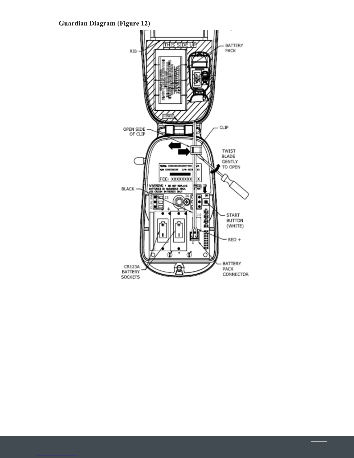
1) Open the top cover of the Guardian opened by loosening the screw at the front of the lid using a 3/16” at screwdriver.
Insert the two batteries into the battery holders at the inside-front of the housing and connect the optional extended life
battery pack if present (J7). Refer to Figure 12
2) Verify that the Guardian’s antenna is pointing straight up.
3) Press the white button on the right side of the unit. A green LED will light up at the inside front of the housing.
4) The green LED will ash fast (half second ON, half second OFF).
5) Once a cellular network is found, the green LED will ash slow (one second ON, one second OFF).
6) The green LED will go to solid ON for about 60 seconds while the unit is transmitting data to MonitorMyGuardian.com.
7) After a successful transmission, the green LED will ash and then go out. The Guardian is now in sleep mode, and will
remain in sleep mode until the next scheduled transmission time or until the white button is pressed again.
8) If the data transmission was not successful, a red LED will light and the green LED will ash an error code. Refer to
Section 8-1 of this manual for information on the error codes.
9) Contact FLO-CORP Customer Service at 1-877-356-5463 to verify a successful data transmission, and to verify tank
information.
10) Secure the top cover. Do not over tighten the screw.
UNIT ACTIVATION
VERIFYING GSM SIGNAL STRENGTH
During installation, you can determine your GSM signal suitability by operating a GSM cellular phone and conrming its
operation capability by placing a call.
(877) 356-5463 | (p) 330-331-7331 | (f) 330-331-7172 | www.FLO-CORP.com | © 2017 FLO-CORP | REVA 1116 13 (877) 356-5463 | (p) 330-331-7331 | (f) 330-331-7172 | www.FLO-CORP.com | © 2017 FLO-CORP | REVA 1116 14

(877) 356-5463 | (p) 330-331-7331 | (f) 330-331-7172 | www.FLO-CORP.com | © 2017 FLO-CORP | REVA 1116 13 (877) 356-5463 | (p) 330-331-7331 | (f) 330-331-7172 | www.FLO-CORP.com | © 2017 FLO-CORP | REVA 1116 14
NORMAL OPERATION
After communication has been established, and the tank information has been given to the FLO-CORP Monitoring Center, the
Guardian 1000™ will continue to transmit data based upon the number of callouts per day set.
This tank data can be accessed through MonitorMyGuardian.com. On this web site, you may view the current level and
status of your devices using a standard web browser (i.e. Microsoft Internet Explorer®, Firefox or any internet browser),
download your historical data to applications such as Microsoft Excel®, or set up alarm levels to automatically trigger events
such as an e-mail or page to a local service or sales representative. The MonitorMyGuardian.com portal is a secure web site
which utilizes the latest in internet encryption technology to ensure that your data stays condential. It is constantly being
upgraded and new features are being added periodically. To obtain the latest details on how to use the new features of the
web site, follow the links to the help section of the web site.
ACCESSING MonitorMyGuardian.com
On your PC, smart phone or tablet with internet connection, go to www.MonitorMyGuardian.com
To view your data on the web you must rst have a Logon and Password. A Logon and Password will be provided to you or
to your representative when the service agreement with FLO-CORP is nalized. If you have forgotten your logon or password
or need a new one, please contact the FLO-CORP Customer Service at 1-877-356-5463.
Once a valid logon and password have been entered, you may select which tanks to view. Tanks may be viewed by
geographical location, product type, region, etc. Once the tank levels are viewed, detailed information for each tank may be
viewed, edited, or the historical data for the tank may be viewed.
When a unit is sold by FLO-CORP, a default tank entry is set up on the web site and it is assigned to the logon. When the
unit is installed, the pertinent information will need to be set up on the web site by the customer. This includes: Tank Name,
Product type, Tank Location, Contact information, etc.

(877) 356-5463 | (p) 330-331-7331 | (f) 330-331-7172 | www.FLO-CORP.com | © 2017 FLO-CORP | REVA 1116 15 (877) 356-5463 | (p) 330-331-7331 | (f) 330-331-7172 | www.FLO-CORP.com | © 2017 FLO-CORP | REVA 1116 16
TROUBLE SHOOTING
ERROR CODES
If the data transmission was not successful from a Guardian 1000™, a red LED will light and the green LED will ash an error
code.
NUMBER OF RED FLASHES ERROR CODE DESCRIPTION
1Internal Hardware Error: Guardian could not initialize properly due to an internal
hardware error. If this problem continues, replace the Guardian unit.
2Low Battery Voltage: Guardian could not transmit due to a low battery voltage. Replace
the batteries and re-try a data transmission.
3Radio Error: The Guardian’s wireless transmitter did not power on properly. Re-try a
data transmission. If this problem continues, replace the Guardian unit.
4
Cellular Service Error: The unit did not detect cellular service. Verify that there is service
in the area using the technique in Section 4.2 or check GSM coverage information on
Web Sites in Section 4.6. Ensure that the antenna is tightly connected to the unit and is
vertical. If still not successful, contact FLO-CORP Customer Service for conrmation of
data channel availability.
5Cellular Busy Error: The Guardian could not transmit because the cellular network is
busy. Re-try data transmission.
6
Radio Respond Error: The Guardian’s wireless transmitter did not respond to the
command to transmit data. Re-try a data transmission. If this problem continues,
replace the Guardian unit.
7
Low RSSI Error: The data transmission failed due to low signal strength Error Code 7 in
Section 7.1. Apply the technique indicated in Section 4.3 to establish the best location
for an external antenna to improve the signal strength.
8
Failed Transmission Error: The data transmission failed. Insert new batteries into the
unit and re-try a data transmission. If this problem continues, contact FLO-CORP
Customer Service.
9Radio Error: The Guardian’s wireless transmitter did not initialize properly. Re-try the
data transmission. If this problem continues, replace the Guardian unit.
10 Memory Error: The Guardian’s memory has been corrupted. If this problem continues,
replace the Guardian unit.

(877) 356-5463 | (p) 330-331-7331 | (f) 330-331-7172 | www.FLO-CORP.com | © 2017 FLO-CORP | REVA 1116 15 (877) 356-5463 | (p) 330-331-7331 | (f) 330-331-7172 | www.FLO-CORP.com | © 2017 FLO-CORP | REVA 1116 16
TROUBLE SHOOTING CONTINUED
Nothing happens when the Start switch is pressed.
Remove all of the batteries. Wait 30 seconds to initialize the Guardian memory and then reinsert the batteries. If
the green LED does not come on when the switch is pressed, replace the batteries with new ones.
Unit cannot transmit to data center.
Verify that the RSSI is greater than 20.
Verify that there is GSM SMS (Short Message Service) on the side selected in the carrier preference setting.
Check for interfering structures such as tanks, buildings, or large equipment.
Reposition the unit if possible.
Check that the antenna connection to the unit is tight.
Verify the Serial Number of the unit on the web site.
Use an external antenna.
The level reading is incorrect
Normally, all of the sensor parameters are set up by your FLO-CORP account representative when the tank is
initially congured. On rare occasions, the information may not be correctly entered. If you have veried the tank
information and the tank level is still incorrect, there may be several causes for the incorrect reading. If it is a
differential pressure sensor, verify the settings for the probe offset and the SGU. Either one of these settings may
cause the reading to be off. If this is a 4-20mA current loop sensor, verify the 4mA and 20mA settings. If either of
these settings is incorrect, then the level that is calculated from the sensor data will be wrong.
Verify the tank height.
The level reading is correct but volume is off
Verify the tank capacity. This should be the volume in the tank at the tank height. If the tank has a slight cone top
but a standard vertical strapping chart is used, then the tank height should be only to the shoulder of the tank.
Verify that the correct strapping chart is used.
The unit has stopped calling
Replace the batteries.
Ensure that the antenna is tight and vertical.

(877) 356-5463 | (p) 330-331-7331 | (f) 330-331-7172 | www.FLO-CORP.com | © 2017 FLO-CORP | REVA 1116 17 (877) 356-5463 | (p) 330-331-7331 | (f) 330-331-7172 | www.FLO-CORP.com | © 2017 FLO-CORP | REVA 1116 18
BATTERY REPLACEMENT
The Guardian tank monitor operates on 2 CR-123A disposable lithium batteries and an extended battery pack. The Guardian
estimates the remaining battery life using a sophisticated algorithm based on the battery voltage and temperature, cellular
signal strength and the number of transmissions and retries that the unit has made. This estimate is transmitted to the
FLO-CORP monitoring center and displayed on the internet. The procedure below outlines the steps necessary to change
dead batteries. Reference Figure 13.
1. Carefully loosen the captive screw at the front of the housing using a 3/16” at screwdriver, then lift the top cover to
expose the electronics and batteries.
2. Remove the two batteries from the battery holder and . Wait 30 seconds to allow the Guardian memory to initialize. Install
three new batteries, making sure the positive end of each battery is towards the back of the electronics.
3. Remove ALL existing batteries: individual and extended life battery pack if equipped. Properly dispose of all expired
batteries and pack. Never mix fresh batteries with partially or fully expired batteries.
4. Insert new batteries into the battery sockets located on the printed circuit card and install the new extended life battery
pack.
Note: Never mix new and used batteries. The Guardian will operate as intended with either the two individual batteries or the
extended life battery pack or with both. See Note 2.
5. START the Guardian: Before closing and securing the lid, press the white START pushbutton and verify the green LED
begins to ash.
6. Call your customer support representative to verify operation. Report any battery conguration changes (2 single batteries
plus Extended Pack versus 2 batteries only versus Extended Pack only) to the customer support representative to ensure
proper battery life indication via the MonitoryMyGuardian.com web portal or update the battery conguration setting from the
Tank Setup page. See detailed instructions for further information.
7. Close the monitor lid. Ensure the gasket seal is secure and ush in the groove of the enclosure base. Failure to do so may
allow moisture to enter the enclosure and damage the electronics.
8. Tighten the locking screw using a small at blade screwdriver.
9. Congratulations you have successfully replaced the batteries. Thank you for your assistance.

(877) 356-5463 | (p) 330-331-7331 | (f) 330-331-7172 | www.FLO-CORP.com | © 2017 FLO-CORP | REVA 1116 17 (877) 356-5463 | (p) 330-331-7331 | (f) 330-331-7172 | www.FLO-CORP.com | © 2017 FLO-CORP | REVA 1116 18

(877) 356-5463 | (p) 330-331-7331 | (f) 330-331-7172 | www.FLO-CORP.com | © 2017 FLO-CORP | REVA 1116 19
G1
Communication(1)(2)(3)
1) GSM Host, 4-20mA uplink
2) GSM Host w/GPS, 4-20mA uplink
3) CDMA Host, 4-20mA uplink
Enclosure Rating (4)
GP) General Purpose
IS) Intrinsically Safe (GSM Host w/GPS option only)
Additional Communication Options (5)
NN) None
GL) GPS w/level
Ordering Information
FLO-CORP MODEL NUMBER BUILDER For Assistance Call 877.356.5463
Use the diagram below, working from left to right to construct your FLO-CORP Model Number.
Simply match the category number to the corresponding box number.
G1
Example: G1-1-GP-NN Guardian 1000™ Wireless Monitoring System with GSM Host, 4-20mA uplink, General Purpose enclosure
with no additional communication options.
Ordering Notes:
(1) Select the best conguration based on your requirements
(2) Monthly service fees will apply. Limit 3 calls per day.
(3) GSM Host indicates that it will connect to AT&T networks. CDMA Host indicates that it will connect to Verizon networks.
(4) The Instrinsically safe enclosure rating can only be used with the GSM Host w/GPS option.
(5) Additional monthly fees may apply
Table of contents
Other Flocorp Measuring Instrument manuals

Popular Measuring Instrument manuals by other brands

 Beta Module user guide")


Bacharach
Bacharach Fyrite INTECH Configuration and operation manual

DynAmp
DynAmp LKAT2 Installation, operation and service manual

Rice Lake
Rice Lake Non-NTEP SENDit Kit installation manual

VEE GEE
VEE GEE BX-1 Operation manual

GW Instek
GW Instek GSP-830 user manual

Endress+Hauser
Endress+Hauser Liquiline System CA80NO operating instructions