Vega VEGAWELL 52 User manual

Operating Instructions
Submersible pressure transmitter with
ceramic measuring cell
VEGAWELL 52
4 … 20 mA
Document ID: 35401

2
Contents
VEGAWELL 52 • 4 … 20 mA
35401-EN-171005
Contents
1 About this document ............................................................................................................... 4
1.1 Function ........................................................................................................................... 4
1.2 Target group ..................................................................................................................... 4
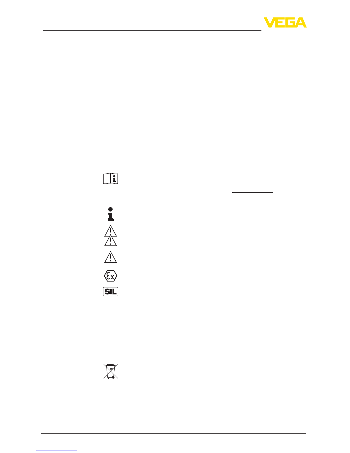
1.3 Symbols used................................................................................................................... 4
2 For your safety ......................................................................................................................... 5
2.1 Authorised personnel ....................................................................................................... 5
2.2 Appropriate use................................................................................................................ 5
2.3 Warning about incorrect use............................................................................................. 5
2.4 General safety instructions............................................................................................... 5
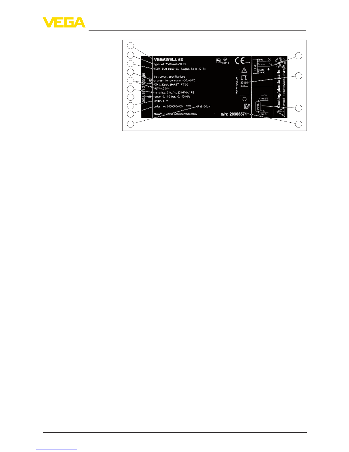
2.5 Safety label on the instrument .......................................................................................... 6
2.6 EU conformity................................................................................................................... 6
2.7 NAMUR recommendations .............................................................................................. 6
2.8 Installation and operation in the USA and Canada ........................................................... 6
2.9 Environmental instructions ............................................................................................... 6
3 Product description ................................................................................................................. 8
3.1 Conguration.................................................................................................................... 8
3.2 Principle of operation........................................................................................................ 9
3.3 Adjustment..................................................................................................................... 10
3.4 Packaging, transport and storage................................................................................... 10
3.5 Accessories and replacement parts ............................................................................... 11
4 Mounting................................................................................................................................. 12
4.1 General instructions ....................................................................................................... 12
4.2 Mounting steps with straining clamp............................................................................... 13
4.3 Mounting steps with screw connection for suspension cable ......................................... 14
4.4 Mounting steps with threaded connection or housing .................................................... 15
5 Connecting to power supply................................................................................................. 16
5.1 Preparing the connection ............................................................................................... 16
5.2 Connection procedure.................................................................................................... 18
5.3 Wiring plan ..................................................................................................................... 18
5.4 Switch-on phase............................................................................................................. 19
6 Maintenanceandfaultrectication...................................................................................... 20
6.1 Maintenance .................................................................................................................. 20
6.2 Rectify faults................................................................................................................... 20
6.3 Shorten suspension cable.............................................................................................. 21
6.4 Shorten suspension cable - Version with housing .......................................................... 21
6.5 How to proceed if a repair is necessary.......................................................................... 23
7 Dismount................................................................................................................................. 24
7.1 Dismounting steps.......................................................................................................... 24
7.2 Disposal ......................................................................................................................... 24
8 Supplement ............................................................................................................................ 25
8.1 Technical data ................................................................................................................ 25
8.2 Dimensions .................................................................................................................... 31
8.3 Industrial property rights................................................................................................. 35

3
Contents
VEGAWELL 52 • 4 … 20 mA
35401-EN-171005
Safety instructions for Ex areas
TakenoteoftheExspecicsafetyinstructionsforExapplications.
These instructions are attached as documents to each instrument
with Ex approval and are part of the operating instructions manual.
Editing status: 2017-09-28

4
1 About this document
VEGAWELL 52 • 4 … 20 mA
35401-EN-171005
1 About this document
1.1 Function
This operating instructions manual provides all the information you
need for mounting, connection and setup of the instrument. Further-
morethereareimportantinstructionsformaintenance,faultrectica-
tion, the exchange of parts and the safety of the user. Please read this
information before putting the instrument into operation and keep this
manual accessible in the immediate vicinity of the device.
1.2 Target group
This operating instructions manual is directed to trained specialist
personnel.The contents of this manual should be made available to
these personnel and put into practice by them.
1.3 Symbols used
Document ID
This symbol on the front page of this instruction refers to the Docu-
ment ID. By entering the Document ID on www.vega.com you will
reach the document download.
Information, tip, note
This symbol indicates helpful additional information.
Caution: If this warning is ignored, faults or malfunctions can result.
Warning: If this warning is ignored, injury to persons and/or serious
damage to the instrument can result.
Danger: If this warning is ignored, serious injury to persons and/or
destruction of the instrument can result.
Ex applications
This symbol indicates special instructions for Ex applications.
SIL applications
This symbol indicates instructions for functional safety which must be
taken into account particularly for safety-relevant applications.
• List
The dot set in front indicates a list with no implied sequence.
→ Action
This arrow indicates a single action.
1 Sequence of actions
Numbers set in front indicate successive steps in a procedure.
Battery disposal
This symbol indicates special information about the disposal of bat-
teries and accumulators.

5
2 For your safety
VEGAWELL 52 • 4 … 20 mA
35401-EN-171005
2 For your safety
2.1 Authorised personnel
All operations described in this operating instructions manual must
be carried out only by trained specialist personnel authorised by the
plant operator.
During work on and with the device the required personal protective
equipment must always be worn.
2.2 Appropriate use
Model VEGAWELL 52 is a pressure transmitter for level and gauge
measurement.
Youcannddetailedinformationabouttheareaofapplicationin
chapter "Product description".
Operational reliability is ensured only if the instrument is properly
usedaccordingtothespecicationsintheoperatinginstructions
manual as well as possible supplementary instructions.
For safety and warranty reasons, any invasive work on the device
beyond that described in the operating instructions manual may be
carried out only by personnel authorised by the manufacturer. Arbi-
traryconversionsormodicationsareexplicitlyforbidden.
2.3 Warning about incorrect use
Inappropriate or incorrect use of the instrument can give rise to
application-specichazards,e.g.vesseloverllordamagetosystem
components through incorrect mounting or adjustment.Thus dam-
age to property, to persons or environmental contamination can be
caused. Also the protective characteristics of the instrument can be
inuenced.
2.4 General safety instructions
This is a state-of-the-art instrument complying with all prevailing
regulations and directives.The instrument must only be operated in a
technicallyawlessandreliablecondition.Theoperatorisresponsi-
ble for the trouble-free operation of the instrument.When measuring
aggressive or corrosive media that can cause a dangerous situation
if the instrument malfunctions, the operator has to implement suitable
measures to make sure the instrument is functioning properly.
During the entire duration of use, the user is obliged to determine the
compliance of the necessary occupational safety measures with the
current valid rules and regulations and also take note of new regula-
tions.
The safety instructions in this operating instructions manual, the na-
tional installation standards as well as the valid safety regulations and
accident prevention rules must be observed by the user.
For safety and warranty reasons, any invasive work on the device
beyond that described in the operating instructions manual may be
carried out only by personnel authorised by the manufacturer. Arbi-

6
2 For your safety
VEGAWELL 52 • 4 … 20 mA
35401-EN-171005
traryconversionsormodicationsareexplicitlyforbidden.Forsafety
reasons,onlytheaccessoryspeciedbythemanufacturermustbe
used.
To avoid any danger, the safety approval markings and safety tips on
the device must also be observed and their meaning looked up in this
operating instructions manual.
2.5 Safety label on the instrument
The safety approval markings and safety tips on the device must be
observed.
2.6 EU conformity
ThedevicefullsthelegalrequirementsoftheapplicableEUdirec-
tives.ByaxingtheCEmarking,weconrmsuccessfultestingofthe
product.
YoucanndtheCECerticateofConformityinthedownloadsection
under "www.vega.com".
2.7 NAMUR recommendations
NAMUR is a user association for automation technology in the
processindustriesinGermany.Severalofitskeyactivitiesareden-
ing standards as well as setting user requirements on new devices,
systems and technologies.The published NAMUR recommendations
(NE)areacceptedasthestandardineldinstrumentation.
ThedevicefullstherequirementsofthefollowingNAMURrecom-
mendations:
• NE 21 – Electromagnetic compatibility of equipment
• NE 43 – Signal level for fault information from measuring transduc-
ers
2.8 Installation and operation in the USA and
Canada
This information is only valid for USA and Canada. Hence the follow-
ing text is only available in the English language.
Installations in the US shall comply with the relevant requirements of
the National Electrical Code (ANSI/NFPA 70).
Installations in Canada shall comply with the relevant requirements of
the Canadian Electrical Code
2.9 Environmental instructions
Protection of the environment is one of our most important duties.
That is why we have introduced an environment management system
with the goal of continuously improving company environmental pro-
tection.Theenvironmentmanagementsystemiscertiedaccording
to DIN EN ISO 14001.
Pleasehelpusfullthisobligationbyobservingtheenvironmental
instructions in this manual:

7
2 For your safety
VEGAWELL 52 • 4 … 20 mA
35401-EN-171005
• Chapter "Packaging, transport and storage"
• Chapter "Disposal"

8
3 Product description
VEGAWELL 52 • 4 … 20 mA
35401-EN-171005
3 Product description
3.1 Conguration
The scope of delivery encompasses:
• VEGAWELL 52 pressure transmitter with suspension cable
• Documentation
– This operating instructions manual
– Testcerticate
– Supplementary instructions "Suitable for drinking water"
(optional)
– Ex-specic"Safety instructions" (with Ex versions)
– Ifnecessary,furthercerticates
Note:
Optional instrument features are also described in this operating
instructions manual.The respective scope of delivery results from the
orderspecication.
VEGAWELL 52 with suspension cable consists of the following
components:
• Transmitter
• Suspension cable
• Optionally, adjustable screw connection for suspension cable or
housing with thread
Thecomponentsareavailableindierentversions.
2
1
Fig. 1: Example of a VEGAWELL 52 with transmitter 22 mm
1 Transmitter
2 Suspension cable
Thetypelabelcontainsthemostimportantdataforidenticationand
use of the instrument:
Scope of delivery
Constituent parts
Type label

9
3 Product description
VEGAWELL 52 • 4 … 20 mA
35401-EN-171005
1
2
3
4
5
7
8
9
10 11
12
13
14
6
Fig. 2: Structure type label VEGAWELL 52 (example)
1 Instrument type
2 Product code
3 Approvals
4 Process temperature
5 Signal output/Operating voltage
6 Materials Transmitter/Measuring cell/Measuring cell seal/Suspension cable
7 Measuring range
8 Cable length
9 Order number
10 Protection rating
11 Serial number of the instrument
12 Assignment suspension cable, temperature
13 ID numbers, instrument documentation
14 Assignment suspension cable, level
The type label contains the serial number of the instrument. With it
youcanndthefollowinginstrumentdataonourhomepage:
• Product code (HTML)
• Delivery date (HTML)
• Order-specicinstrumentfeatures(HTML)
• Operating instructions at the time of shipment (PDF)
• Testcerticate(PDF)-optional
Go to "www.vega.com", "VEGA Tools" and "Instrument search". Enter
the serial number.
Alternatively, you can access the data via your smartphone:
• Download the VEGA Tools app from the "Apple App Store" or the
"Google Play Store"
• Scan the Data Matrix code on the type label of the instrument or
• Enter the serial number manually in the app
3.2 Principle of operation
Model VEGAWELL 52 is suitable for continuous level measurement of
liquids.Typical applications are measurements in water/waste water
facilities, deep wells and in the shipbuilding industry.
The actual sensor element is the CERTEC®measuring cell with rug-
ged ceramic diaphragm.The hydrostatic pressure causes a capaci-
Serial number - Instru-
ment search
Application area
Functional principle

10
3 Product description
VEGAWELL 52 • 4 … 20 mA
35401-EN-171005
tance change in the measuring cell via the ceramic diaphragm.This
change is converted into an appropriate output signal.
As a standard feature, the CERTEC®measuring cell is equipped with
a lateral, recessed seal.
Instruments with double seal have an additional front seal.
1
2
3
4
5
Fig. 3: Front-ush installation of the CERTEC®measuring cell with double seal
1 Housing, sensor
2 Measuring cell
3 Lateral seal for measuring cell
4 Additional, front seal for measuring cell
5 Diaphragm
4 … 20 mA two-wire electronics for voltage supply and measured
value transmission on the same cable.
Thedataforpowersupplyarespeciedinchapter"Technical data".
3.3 Adjustment
VEGAWELL 52 with 4 … 20 mA electronics has no adjustment op-
tions.
3.4 Packaging, transport and storage
Your instrument was protected by packaging during transport. Its
capacity to handle normal loads during transport is assured by a test
based on ISO 4180.
The packaging of standard instruments consists of environment-
friendly, recyclable cardboard. For special versions, PE foam or PE
foil is also used. Dispose of the packaging material via specialised
recycling companies.
Transport must be carried out in due consideration of the notes on the
transport packaging. Nonobservance of these instructions can cause
damage to the device.
The delivery must be checked for completeness and possible transit
damage immediately at receipt. Ascertained transit damage or con-
cealed defects must be appropriately dealt with.
Seal concept
Voltage supply
Packaging
Transport
Transport inspection

11
3 Product description
VEGAWELL 52 • 4 … 20 mA
35401-EN-171005
Up to the time of installation, the packages must be left closed and
stored according to the orientation and storage markings on the
outside.
Unless otherwise indicated, the packages must be stored only under
the following conditions:
• Not in the open
• Dry and dust free
• Not exposed to corrosive media
• Protected against solar radiation
• Avoiding mechanical shock and vibration
• Storage and transport temperature see chapter "Supplement -
Technical data - Ambient conditions"
• Relative humidity 20 … 85 %
With an instrument weight of more than 18 kg (39.68 lbs) suitable and
approved equipment must be used for lifting and carrying.
3.5 Accessories and replacement parts
The VEGABOX 03 is a breather housing for VEGAWELL 52.The
housingcontainsalterelementforventilation.
Youcanndfurtherinformationintheoperatinginstructions"Breather
housing with ventilation lter" (Document-ID 45925).
The VEGADIS 82 is suitable for measured value indication of
4 … 20 mA sensors. It is looped into the signal cable.
Youcanndfurtherinformationintheoperatinginstructions
"VEGADIS 82" (Document-ID 46591).
The measuring instrument holder is used for wall/tube mounting of
VEGABAR series 80 pressure transmitters and VEGAWELL 52 sub-
mersible pressure transmitters. Supplied reducers enable the adapta-
tiontodierentinstrumentdiameters.Thematerialusedis316L.
Youcanndadditionalinformationintheoperatinginstructions
"Mounting accessory pressure" (Document-ID 43478).
The robust, heavy-duty bracket of 1.4301/304 is designed for wall
mounting VEGA instruments.The required fastening elements are
included in the shipment.
Storage
Storage and transport
temperature
Lifting and carrying
VEGABOX 03
VEGADIS 82
Measuring instrument
holder
Mounting bracket

12
4 Mounting
VEGAWELL 52 • 4 … 20 mA
35401-EN-171005
4 Mounting
4.1 General instructions
Make sure that all parts of the instrument coming in direct contact
with the process, especially the sensor element, process seal and
processtting,aresuitablefortheexistingprocessconditions,such
as process pressure, process temperature as well as the chemical
properties of the medium.
Youcanndthespecicationsinchapter"Technical data" and on the
nameplate.
The instrument is suitable for standard and extended ambient condi-
tions acc. to DIN/EN/IEC/ANSI/ISA/UL/CSA 61010-1.
Depending on the transmitter, the VEGAWELL 52 is supplied with a
protective cap or a transport and mounting protection.
1
2
Fig. 4: VEGAWELL 52, transport and mounting protection
1 Transmitter
2 Transport and mounting protection
Remove this protection after mounting and before setting up the
instrument.
In case of slightly contaminated measured media, the transport and
mounting protection can remain on the instrument as an impact pro-
tection during operation.
Lateral movements of the transmitter can cause measurement errors.
For this reason, mount the instrument in a calm area or in a suitable
protective tube.
The suspension cable has a capillary for atmospheric pressure com-
pensation.Therefore lead the cable end into a dry environment or a
suitable terminal housing, for example VEGABOX 03 or VEGADIS 82.
Suitability for the process
conditions
Suitability for the ambient
conditions
Transport and mounting
protection
Installation position
Pressure compensation

13
4 Mounting
VEGAWELL 52 • 4 … 20 mA
35401-EN-171005
Fig. 5: Mounting example: VEGAWELL 52 in an open basin with breather hous-
ing VEGABOX 03
4.2 Mounting steps with straining clamp
2
3
1
Fig. 6: Straining clamp
1 Suspension cable
2 Suspension opening
3 Clamping jaws
Mount VEGAWELL 52 with straining clamp as follows:
1. Hang the straining clamp on a suitable wall hook
2. Lower VEGAWELL 52 to the requested height
3. Slide the clamping jaws upward and push the suspension cable
between them
4. Hold the suspension cable, push the clamping jaws downward
andxthemwithalightblow
Disassembly is carried out in reverse order.
Mounting example

14
4 Mounting
VEGAWELL 52 • 4 … 20 mA
35401-EN-171005
4.3 Mounting steps with screw connection for
suspension cable
1
2
3
4
5
6
Fig. 7: Conguration, screw connection of suspension cable
1 Suspension cable
2 Sealing screw
3 Cone bushing
4 Seal cone
5 Screw connection for suspension cable
6 Seal
Mount VEGAWELL 52 with screw connection for suspension cable as
follows:
1. Weld the welded socket into the vessel top
2. Lower VEGAWELL 52 to the requested height by means on the
welded socket G1½ or 1½ NPT on the vessel side
3. Shift the suspension cable from below through the opened
threadedtting
4. Slide the sealing cone and the cone sleeve over the suspension
cable, fasten manually with the seal screw
5. Screw the screwed connection into the socket, tighten with
SW 30 and then tighten seal screw with SW 19
How to correct the height:
1. Loosen seal screw with SW 19
2. Slide seal cone and cone sleeve to the requested position on the
cable
3. Fasten the seal screw
Disassembly is carried out in reverse order.

15
4 Mounting
VEGAWELL 52 • 4 … 20 mA
35401-EN-171005
4.4 Mounting steps with threaded connection or
housing
2
3
1
Fig. 8: Plastic housing
1 Housing
2 Seal
3 Thread
Mount VEGAWELL 52 as follows:
1. Weld the welded socket G1½ A or 1½ NPT to the vessel top
2. Shift transmitter through the mounting boss
3. Turn the thread with seal into the socket and tighten with SW 461)
Disassembly is carried out in reverse order.
Mount VEGAWELL 52 as follows:
1. Fasten the mounting bracket at the suitable height on the basin
wall
2. Lead the transmitter through the opening of the mounting bracket
and the counter nut
3. Fasten counter nut with SW 46 on the thread
Mount into the vessel
Mounting into the basin
1) Seal with resistant material with thread 1½ NPT.

16
5 Connecting to power supply
VEGAWELL 52 • 4 … 20 mA
35401-EN-171005
5 Connecting to power supply
5.1 Preparing the connection
Generally connect the instrument only in the complete absence of line
voltage.
The instrument is equipped with an integrated overvoltage protection.
For additional protection of the signal circuit, we recommend further
external overvoltage arresters.
• Type B63-48 (use with VEGAWELL 52 with plastic housing) or
• Type ÜSB 62-36G.X (use in a separate housing)
Inhazardousareasyoumusttakenoteoftherespectiveregulations,
conformityandtypeapprovalcerticatesofthesensorsandpower
supply units.
Power and current signal are carried on the same 2-wire conductor in
thesuspensioncable.Thevoltagesupplyrangecandierdepending
on the instrument version.
Thedataforpowersupplyarespeciedinchapter"Technical data".
Provide a reliable separation between the supply circuit and the
mains circuits according to DIN EN 61140 VDE 0140-1.
VEGA power supply units VEGATRENN 149AEx, VEGASTAB 690,
VEGADIS 371 as well as all VEGAMETs meet this requirement.When
using one of these instruments, protection class III is ensured for
VEGAWELL 52.
Keepinmindthefollowingadditionalinuencesontheoperating
voltage:
• Output voltage of the power supply unit can be lower under nomi-
nal load (with a sensor current of 20.5 mA or 22 mA in case of fault
message)
• Inuenceofadditionalinstrumentsinthecircuit(seeloadvaluesin
chapter "Technical data")
The instrument is connected with standard two-wire installation cable
without screen. If electromagnetic interference is expected which
is above the test values of EN 61326 for industrial areas, screened
cable should be used.
Make sure that the cable used has the required temperature resist-
anceandresafetyformax.occurringambienttemperature
Use cable with round cross-section. A cable outer diameter of
5…9mm(0.2…0.35in)ensuresthesealeectofthecablegland.
Ifyouareusingcablewithadierentdiameterorcross-section,
exchange the seal or use a suitable cable gland.
Safety instructions
Take note of safety
instructions for Ex
applications
Select power supply
Select installation cable

17
5 Connecting to power supply
VEGAWELL 52 • 4 … 20 mA
35401-EN-171005
1
2
3
Fig. 9: Connect VEGAWELL 52 to power supply
1 Direct connection
2 Connection via VEGABOX 03
3 Connection via housing
If screened cable is required, we recommend connecting the cable
screen on both ends to ground potential. In the connection housing of
the sensor or in VEGABOX 03, the screen must be connected directly
to the internal ground terminal.The ground terminal on the outside of
the housing must be connected to the ground potential (low imped-
ance).
In Ex systems, the grounding is carried out according to the installa-
tion regulations.
In electroplating plants as well as plants for cathodic corrosion protec-
tionitmustbetakenintoaccountthatsignicantpotentialdierences
exist.This can lead to unacceptably high currents in the cable screen
if it is grounded at both ends.
Information:
Themetallicpartsoftheinstrument(processtting,sensor,concen-
tric tube, etc.) are connected with the internal and external ground
terminal on the housing.This connection exists either directly via
the conductive metallic parts or, in case of instruments with external
electronics, via the screen of the special connection cable.
Youcanndspecicationsonthepotentialconnectionsinsidethe
instrument in chapter "Technical data".
Cable screening and
grounding

18
5 Connecting to power supply
VEGAWELL 52 • 4 … 20 mA
35401-EN-171005
5.2 Connection procedure
Proceed as follows:
1. Wire the suspension cable up to the connection compartment2)
2. Connect the wire ends to the screw terminals according to the
wiring plan
Connect the VEGAWELL 52 according to the description in the oper-
ating instructions of the respective VEGABOX.
5.3 Wiring plan
4
1
2
2
3
Fig. 10: Wire assignment, suspension cable
1 Blue (-): to power supply or to the processing system
2 Brown (+): to power supply or to the processing system
3 Shielding
4 Breather capillaries with lter element
2
3
+
1
-
Fig. 11: Wiring plan VEGAWELL 52 for 4 … 20 mA, 4 … 20 mA/HART
1 To the sensor
2 To power supply or processing system
3 Shielding3)
Wire number Wire colour/Polarity Terminal
1 brown (+) 1
2 blue (-) 2
Shielding Grounding
Direct connection
Connection via VEG-
ABOX 02 or VEGABOX 03
Direct connection
Connection via VEG-
ABOX 03
2) The suspension cable is already preconfectioned. After shortening the sus-
pension cable, fasten the type plate with support again to the cable.
3) Connect screen to ground terminal. Connect ground terminal on the outside
of the housing to ground as prescribed.The two terminals are galvanically
connected.

19
5 Connecting to power supply
VEGAWELL 52 • 4 … 20 mA
35401-EN-171005
1
2
4
5
3
6
1
2
Fig. 12: Wiring plan housing
1 To power supply or processing system
13
2
Sensor
12
+
( ) (-)
power supply
34
+
( ) (-)
Fig. 13: Wiring plan VEGAWELL 52 for 4 … 20 mA sensors
1 To the sensor
2 Terminal for connection of the cable screen
3 For power supply
Wire number Wire colour/Polarity Terminal VEGADIS 82
1 brown (+) 1
2 blue (-) 2
Shielding Ground terminal
5.4 Switch-on phase
After connecting VEGAWELL 52 to power supply or after a voltage
recurrence, the instrument carries out a self-check:
• Internal check of the electronics
• 4 … 20 mA output jumps to the failure signal
Aftertherun-upperiod(specicationsee"Technical data"), the instru-
ment delivers an output signal of 4 … 20 mA.The value corresponds
to the actual level as well as the settings already carried out, e.g.
factory setting.
Connection via housing
Connection via
VEGADIS 82

20
6Maintenanceandfaultrectication
VEGAWELL 52 • 4 … 20 mA
35401-EN-171005
6 Maintenanceandfaultrectication
6.1 Maintenance
If the device is used properly, no special maintenance is required in
normal operation.
Insomeapplications,productbuilduponthediaphragmcaninuence
the measuring result. Depending on the sensor and application, take
precautions to ensure that heavy buildup, and especially a hardening
thereof, is avoided.
If necessary, clean the diaphragm. Make sure that the materials are
resistant against the cleanig, see resistance list under "Service" on
"www.vega.com".
6.2 Rectify faults
The operator of the system is responsible for taking suitable meas-
ures to rectify faults.
VEGAWELL52oersmaximumreliability.Nevertheless,faultscan
occur during operation.These may be caused by the following, e.g.:
• Sensor
• Process
• Voltage supply
• Signal processing
Therstmeasuretotakeistochecktheoutputsignal.Inmanycases,
thecausescanbedeterminedthiswayandthefaultsquicklyrectied.
Should these measures not be successful, please call in urgent cases
the VEGA service hotline under the phone no. +49 1805 858550.
Thehotlineismanned7daysaweekround-the-clock.Sinceweoer
this service worldwide, the support is only available in the English
language.The service is free, only standard call charges are incurred.
Connect a multimeter in the suitable measuring range according to
the wiring plan.
Error code Cause Rectication
4 … 20 mA
signal not
stable
No atmospheric pres-
sure compensation
– Check the capillariy and cut it clean
– Check the pressure compensa-
tionandcleanthelterelement,if
necessary
Maintenance
Cleaning
Reaction when malfunc-
tion occurs
Causes of malfunction
Faultrectication
24 hour service hotline
Check the 4 … 20 mA
signal
Other manuals for VEGAWELL 52
3
Table of contents
Other Vega Measuring Instrument manuals

Vega
Vega VEGABAR 82 User manual

Vega
Vega VEGAPULS 66 User manual

Vega
Vega vegacap 62 User manual

Vega
Vega VEGAPULS 66 User manual

Vega
Vega FiberFlex LFXG-H User manual

Vega
Vega VEGAPULS WL 61 User manual

Vega
Vega VEGACAP 27 User manual

Vega
Vega VEGAPULS 61 User manual

Vega
Vega VEGAMIP R62 User manual

Vega
Vega VEGACAP 67 User manual

Vega
Vega VEGASWING 63 User manual

Vega
Vega VEGAPULS 64 User manual

Vega
Vega VEGACAL 63 User manual

Vega
Vega plicscom User manual

Vega
Vega VEGACAP 69 User manual

Vega
Vega DSGH User manual

Vega
Vega VEGACAL 63 User manual

Vega
Vega VEGADIS 371 Ex User manual

Vega
Vega VEGAWELL S 51 User manual

Vega
Vega VEGAPULS SR 68 User manual