Flomotion Systems 2001H Series User manual

2001H Series
Peristaltic Chemical Feed Pump
2001H Series Peristaltic Pump O&M Manual
Installation and Operation Manual
2001H Series
Peristaltic Chemical Feed Pump
May 2017
Flomotion Systems, Inc.
165 Creekside Drive Suite 112
Buffalo NY 14228-2103
Toll Free: (800) 909-3569
Tel: (716) 691-3941
Fax: (716) 691-1253
Flomotion Systems Inc. 2001H Series
Pg. 2

2001H Series Peristaltic Pump O&M Manual
TAB E OF CONTENTS
Table of Contents
1.0 - SYSTEM OVERVIEW.....................................................................................................................................................................4
1.1 SAFETY...............................................................................................................................................................................................4
1.2 WARRANTY.........................................................................................................................................................................................4
1.3 RECEI ING..........................................................................................................................................................................................5
1.4 CUSTOMER MODIFICATION...................................................................................................................................................................5
1.5 INFORMATION FOR RETURNING PUMPS ................................................................................................................................................5
2.0 – 2001H SERIES PUMP AND PUMPHEAD....................................................................................................................................6
2.1 TUBING, SPINDLE AND CO ER INSTALLATION.......................................................................................................................................7
2.2 MOUNTING PUMP ON GEARBOX, INSTALLATION OF COLLET.................................................................................................................8
2.3 PUMP MOUNTING AND COLLET INSTALLATION PROCEDURE..................................................................................................................9
2.4 TUBE AND ROLLER INSTALLATION.....................................................................................................................................................10
2.5 TUBING & CONNECTIONS...................................................................................................................................................................16
Tubing and Accessory Part Numbers...............................................................................................................................................17
3.0 – 2001H MOTOR & GEARBOX.....................................................................................................................................................18
3.1 MOTOR SPECIFICATIONS....................................................................................................................................................................18
3.3 GEARHEAD SPECIFICATIONS...............................................................................................................................................................18
4.0 – 4 SERIES PUMP CONTROLLER............................................................................................................................................19
4.1 OPERATION AND WIRING...................................................................................................................................................................19
4.2 PROGRAMMING .................................................................................................................................................................................19
4.3 INTERFACING TO THE 2001H K4 SERIES PUMP CONTROLLER..........................................................................................................20
5.0 - 2001 SERIES TUBING RUPTURE DETECTOR.......................................................................................................................21
RUPTURE DETECTOR SYSTEM O ER IEW.................................................................................................................................................21
5.1 ALARM CAUSES.................................................................................................................................................................................21
5.2 WHAT TO DO IN AN ALARM CONDITION...............................................................................................................................................21
5.3 RESETTING THE ALARM......................................................................................................................................................................21
5.4 RESUMING SER ICE...........................................................................................................................................................................21
Flomotion Systems Inc. 2001H Series
Pg. 3

2001H Series Peristaltic Pump O&M Manual
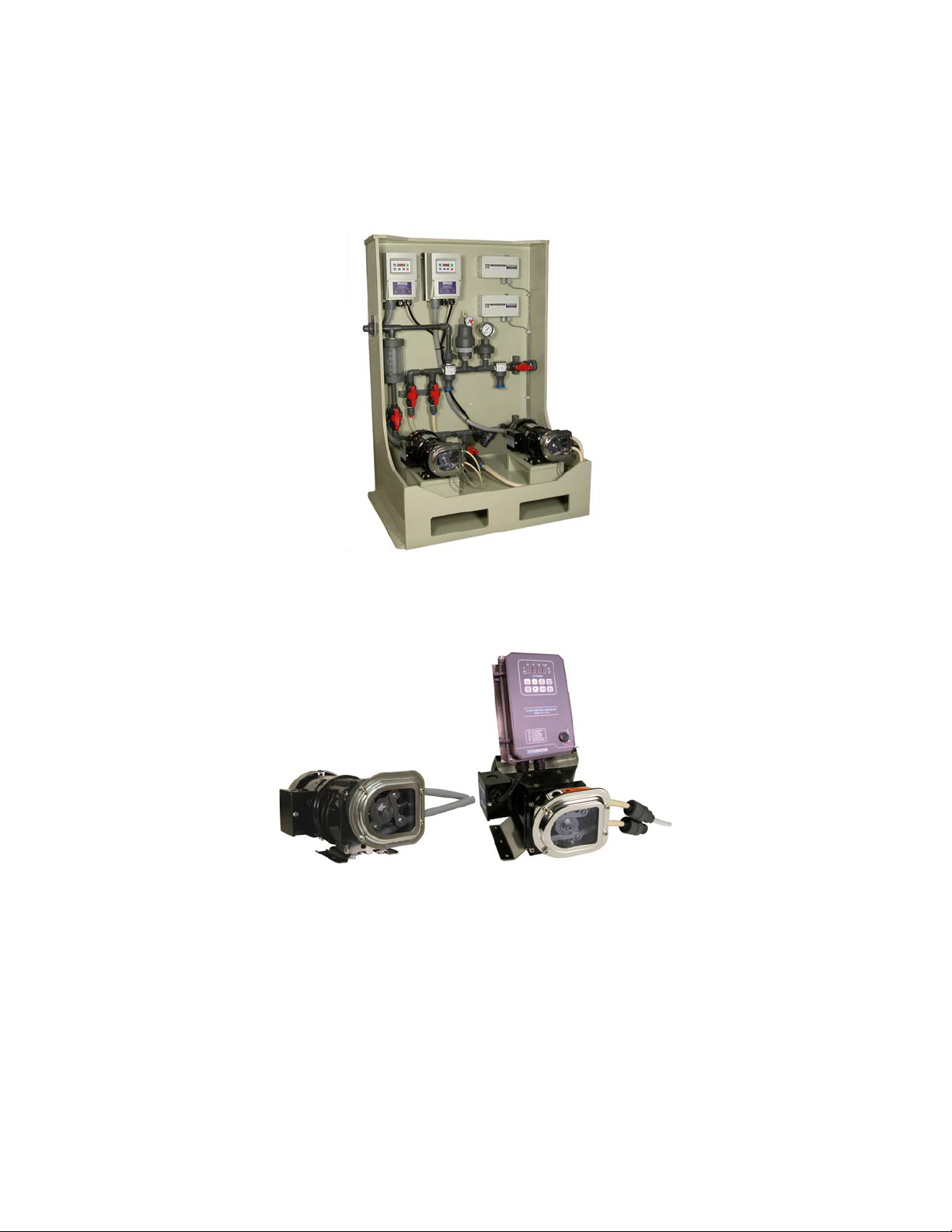
1.0 - System Overview
The 2001H Series Chemical Feed Pump consists of a controller motor gearbox and peristaltic pump.
Model 2001H
with wall mount controller.
Model 2001H
with pump-mounted controller
1.1 Safety
In the interests of safety this pump and the tubing selected should only be used by competent suitably trained
personnel after they have read and understood this manual and considered any hazard involved. Any person
who is involved in the installation or maintenance of this equipment should be fully competent to carry out the
work.
Maintenance and repair should be performed by qualified personnel only. Make sure that no
voltage is applied while work is being carried out on the pump or motor. The motor must be
secured against accidental start up.
1.2 Warranty
Flomotion Systems Inc. warrants the 2001 Series pumps to be free of defects in material and workmanship for
a period of eighteen months from the date of sale to the user or two years from the date of shipment which
ever occurs first. An MC Series control or any component contained therein which under normal use becomes
defective within the stated warranty time period shall be returned to Flomotion Systems Inc. freight prepaid
for examination (contact Flomotion Systems Inc. for authorization prior to returning any product). Flomotion
Systems Inc. reserves the right to make the final determination as to the validity of a warranty claim and sole
obligation is to repair or replace only components which have been rendered defective due to faulty material
or workmanship. No warranty claim will be accepted for components which have been damaged due to
mishandling improper installation unauthorized repair and/or alteration of the product operation in excess of
design specifications or other misuse or improper maintenance. Flomotion Systems Inc. makes no warranty
that its products are compatible with any other equipment or to any specific application to which they may be
applied and shall not be held liable for any other consequential damage or injury arising from the use of its
products. This warranty is in lieu of all other warranties expressed or implied. No other person firm or
corporation is authorized to assume for Flomotion Systems Inc. any other liability in connection with the
demonstration or sale of its products.
Flomotion Systems Inc. 2001H Series
Pg. 4

2001H Series Peristaltic Pump O&M Manual
1.3 Receiving
Inspect all cartons for damage which may have occurred during shipping. Carefully unpack equipment and
inspect thoroughly for damage or shortage. Report any damage to carrier and/or shortages to supplier. All
major components and connections should be examined for damage and tightness with special attention given
to PC boards plugs knobs and switches.
1.4 Customer Modification
Flomotion Systems Inc. its sales representatives and distributors welcome the opportunity to assist our
customers in applying our products. Many customizing options are available to aid in this function. Flomotion
Systems Inc. cannot assume responsibility for any modifications not authorized by its engineering department.
1.5 Information for Returning Pumps
Equipment that has been contaminated with or exposed to body fluids toxic chemicals or any other
substance hazardous to health must be decontaminated before it is returned to Flomotion Systems or its
distributor.
A certificate included at the rear of these operating instructions or signed statement must be attached to the
outside of the shipping container.
This certificate is required even if the pump is unused. If the pump has been used the fluids that have been in
contact with the pump and the cleaning procedure must be specified along with a statement that the equipment
has been decontaminated.
Flomotion Systems Inc. 2001H Series
Pg. 5

2001H Series Peristaltic Pump O&M Manual
2.0 – 2001H Series Pump and Pumphead
The 2001H Series pumphead has two spring-loaded working rollers which automatically compensate for minor
variations in tubing wall thickness giving extended tube life.
IMPORT NT: The 2001 Series is equipped with a pump cover for safety and protection against
chemical spills. The cover must be installed whenever the pump is in use.
Flomotion Systems Inc. 2001H Series
Pg. 6
ROLLER ASSEMBLY
COLLET SCREW
5MM HEX WRENCH
7 NT.M 60 IN.OZ

2001H Series Peristaltic Pump O&M Manual
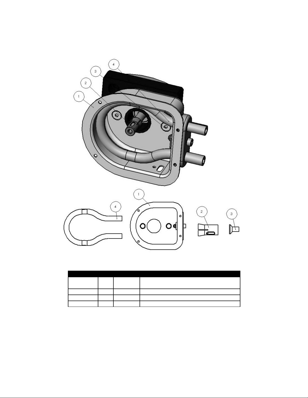
2.1 Tubing Spindle and Cover Installation
! IMPORTANT: Disconnect pump controller from power supply BEFORE changing tubing!
Item No. Qty Part No. Description
1 1 n/a Pump Body
2 1 100511 Roller Assembly
3 1 100304B Cover
4 1 100324 Collet Screw
5 1 100305C Cover Gasket
6 4 100307C Cover Screw
7 1 varies Tubing
8 1 Varies with tubing selection* Tube Seal
*Tube Seal PN 100329 100330 100331 100332 100333 100334
Flomotion Systems Inc. 2001H Series
Pg. 7
Tubing is shown bent forward out of the pump
housing to illustrate the correct tubing and roller
assembly position prior to sliding the tubing and
spindle into the housing and over the collet.
8
2001H Series Peristaltic Pump O&M Manual
2.2 Mounting Pump on Gearbox, Installation of Collet
Item No. Qty Part No. Description
1 1 na Pump Housing with Tube Seal & Tube
Seal Cover
2 1 100306 Collet
3 2 100312 Pump Mounting Screws
4 1 na Tubing
Flomotion Systems Inc. 2001H Series
Pg. 8

2001H Series Peristaltic Pump O&M Manual
2.3 Pump Mounting and Collet Installation Procedure
1. To install the pump housing on the gearbox slide it over the central pilot on the gearbox adaptor plate.
Next install and torque the mounting screws to 5 NT.M (45 in. oz).
2. Next install the collet on the gearbox shaft. There is a slot in the collet that the flat drive tang on the
gearbox shaft must slide into. Orient the collet to allow the drive tang to slide into the slot and push the
collet completely onto the gearbox shaft. When the collet bottoms out it is in the correct position.
Flomotion Systems Inc. 2001H Series
Pg. 9
2001H Series Peristaltic Pump O&M Manual
2.4 Tube and Roller Installation
! IMPORT NT: Disconnect pump controller from power supply BEFORE changing tubing!
! IMPORT NT Make sure pump suction and discharge lines are completely drained and
isolated. Note that the tubing hose seal size must match the selected tubing size.
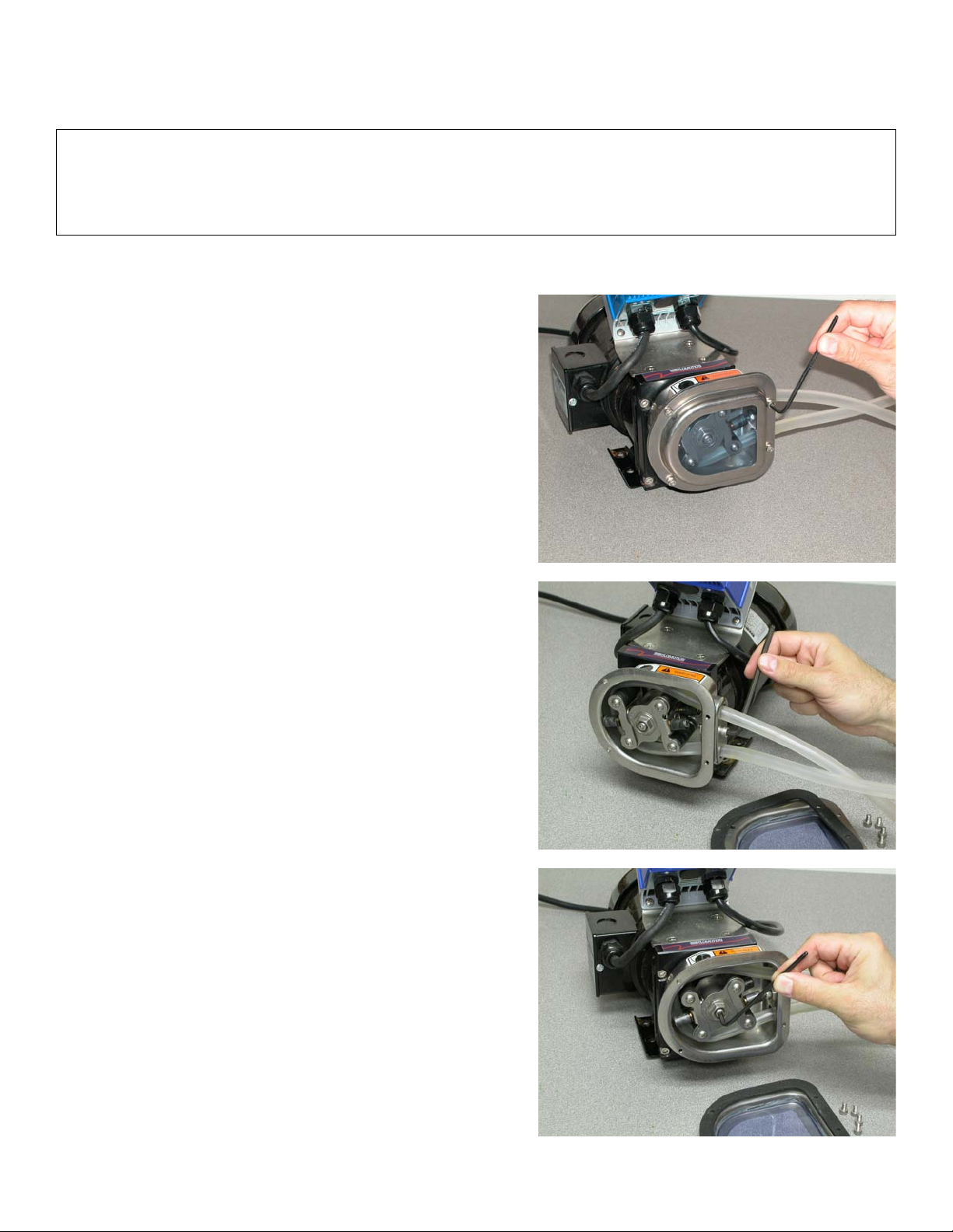
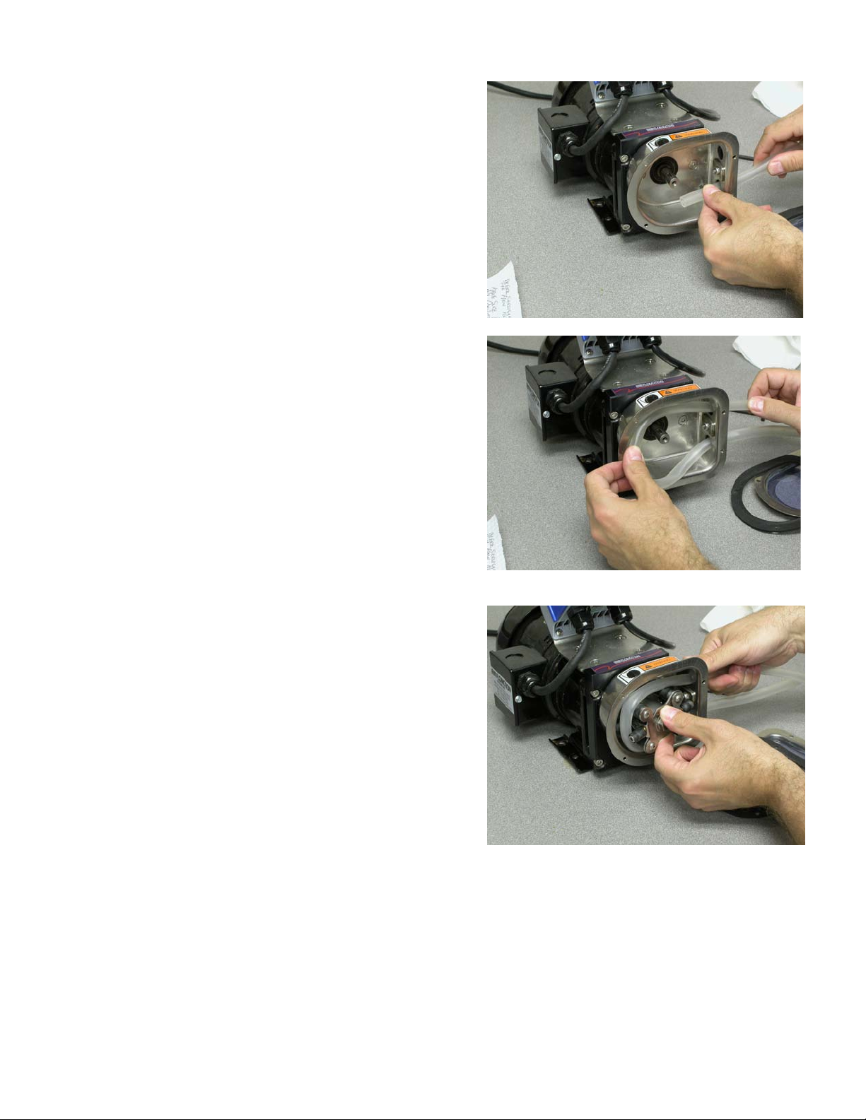
Disassembly
1. Remove four (4) 4mm pump cover screws.
2. Loosen Tube Seal Clamp Screw with 5mm hex
wrench.
3. Remove 5mm collet screw.
Flomotion Systems Inc. 2001H Series
Pg. 10

2001H Series Peristaltic Pump O&M Manual
4. Remove the roller assembly.
5. Remove worn pump tubing from pumphead.
6. Remove and inspect collet for wear. Note that the
collet may remain in the roller assembly when the
roller assembly is removed from the pump shaft.
Flomotion Systems Inc. 2001H Series
Pg. 11
2001H Series Peristaltic Pump O&M Manual
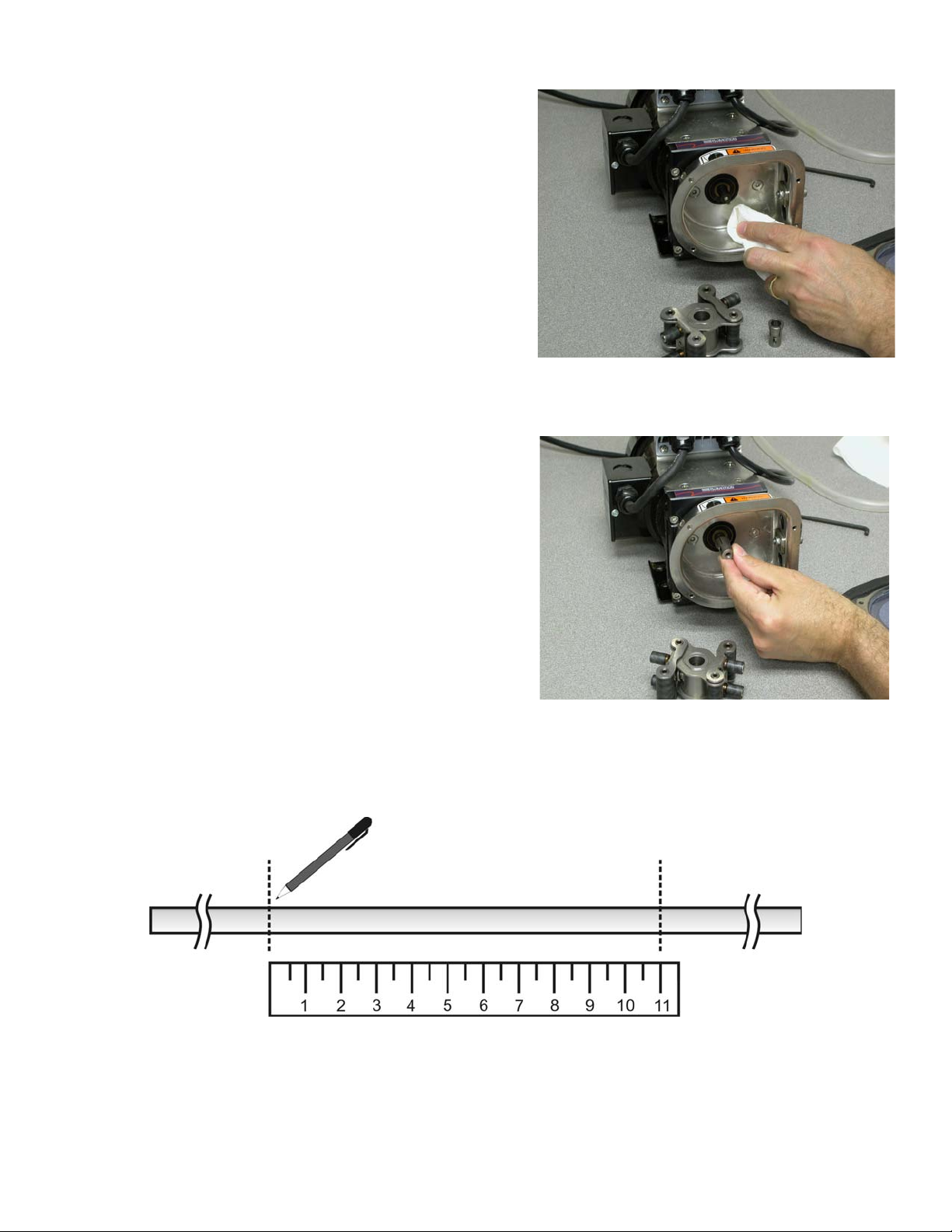
7. Clean inside of pump housing with damp rag or an
appropriate cleaning solution to remove any chemical
or tubing residue.
Reassembly
1. Reinstall the collet onto the pump shaft.
There is a slot in the collet that the flat drive tang on the
gearbox shaft must slide into. Orient the collet to allow the
drive tang to slide into the slot and push the collet
completely onto the gearbox shaft. When the collet
bottoms out it is in the correct position.
2. Mark an 11” section of tubing which will be the portion contained within the pump. Leave sufficient
excess on the suction and discharge sides of the pump for the desired connections. If you leave the
excess intake tubing in a coil near the pump it will make it easy to feed a new section of tubing through
the rollers when the section in the pump becomes worn.
Flomotion Systems Inc. 2001H Series
Pg. 12
Mark an 11”
section of pump tubing.
2001H Series Peristaltic Pump O&M Manual
3. Install tubing into the pumphead.
Note: during tubing installation the loop of tubing may
develop a twist. Examine the tubing for this condition
and if needed turn one end of the tubing where it
exits the tubing clamp to eliminate the twist. Correctly
adjusted the tubing loop will be flat and parallel to the
front face of the pump housing.
4. Loop tubing around roller assembly between guides
as shown. Remove slack in tubing while rotating
roller assembly and sliding onto collet.
Flomotion Systems Inc. 2001H Series
Pg. 13

2001H Series Peristaltic Pump O&M Manual
5. Align marks on tubing with outside edge of the tubing
Clamp.
6. Reinstall collet screw firmly.
7. Tighten tubing seal clamp screw. Be sure to tighten
firmly to prevent “tubing walk.” Tubing walk can occur
when the tubing seal is the wrong size or is not
sufficiently tight to keep the rollers from pulling the
tubing through the pump as it rotates.
Flomotion Systems Inc. 2001H Series
Pg. 14
Align the tubing marks
with the outside edge
of the Hose Seal.
Tubing seal size
varies with the
selected tubing size.
See tables on
following pages for
details
Mark an 11 inch
length of tubing
and locate the
marks at the
outside edge of
the tubing seal
(see arrows)

2001H Series Peristaltic Pump O&M Manual
8. Inspect pump cover gasket. Replace if damaged.
Reinstall pump cover gasket and cover.
Flomotion Systems Inc. 2001H Series
Pg. 15

2001H Series Peristaltic Pump O&M Manual
2.5 Tubing & Connections
Tubing adapters are available for many configurations. See the drawing below for details.
Hose Barb
Color
Violet Green White Black Gray Blue
Hose Seal
PN
100329 100330 100331 100332 100333 100334
Flomotion Systems Inc. 2001H Series
Pg. 16

2001H Series Peristaltic Pump O&M Manual
Tubing and Accessory Part Numbers
FLOPRENE TUBING - 50 Ft Length (Santoprene)
FLO.016.024 1.6mm (1/16”) bore 100 PSI max
FLO.032.024 3.2mm (1/8”) bore 100 PSI max
FLO.048.024 4.8mm (3/16”) bore 70 PSI max
FLO.064.024 6.4mm (1/4”) bore 50 PSI max
FLO.080.024 8.0mm (5/16”) bore 30 PSI max
FLO.096.024 9.6mm (3/8”) bore 30 PSI max
CONNECTORS / ADAPTORS
1/2” NPTM x pump tubing (bore as required)
3/8” PE tubing x pump tubing (bore as required)
Two-piece Color Coded tubing Barb & Collar Set.
PUMPHEAD tubing SEALS
100329 tubing Seal 1.6mm (1/16”) bore
100330 tubing Seal 3.2mm (1/8”) bore
100331 tubing Seal 4.8mm (3/16” bore
100332 tubing Seal 6.4mm (1/4”) bore
100333 tubing Seal 8.0mm (5/16”) bore
100334 tubing Seal 9.6mm 3/8”) bore
Flomotion Systems Inc. 2001H Series
Pg. 17

2001H Series Peristaltic Pump O&M Manual
3.0 – 2001H Motor & Gearbox
3.1 Motor Specifications
Motor Type: Permanent Split Capacitor or 3-Phase Inverter Duty
Rotation: Reversible.
Insulation: Class B minimum
Finish: Powder-coat gloss black.
Thermostat signal wires are not used in the 2001H
3.2 2001H Power & Motor Wiring
3.3 Gearhead Specifications
Housing: Precision machined die cast aluminum.
Lubrication: Lifetime oil bath sealed and gasketed.
Shafts: Hardened steel.
Mounting: Face (any angle) or optional footplate.
Gearing: AGMA class 9 heat treated steel. 1st stage helical metal balance spur metal.
Bearings: Needle with thrust ball.
Flomotion Systems Inc. 2001H Series
Pg. 18

2001H Series Peristaltic Pump O&M Manual
4.0 – K4 SERIES Pump Controller
4.1 Operation and Wiring
For complete details about the pump controller please refer to the included K4 SERIES (KBDA) Drive
Controller Operating Instructions booklet.
Shown here are program settings specific to the operation with the 2001H Series Peristaltic Pump.
4.2 Programming
The K4 SERIES programming differs from the factory defaults shown in the Operating Instruction booklet in
relation to the following parameters:
0.04 = 0000 GFCI operation disabled
1.00 = 0001 Remote Start/Stop input enabled
1.05 = 0003 Auto restart after power failure or fault
2.01 = 0001 Update speed change w/o having to press ENTER
2.02 = 0002 Local/Remote select input enabled
3.02 = 0100 100Hz Full Scale
4.00 = 0000 Display in Hz
5.00 = 0000 Run Relay output enabled
7.03 = 0010 Remote Start/Stop output enabled
7.04 = 0000 External Local/Remote select input OFF (0013 = ON)
7.06 = 0008 External Fault Input enabled
8.00 = 0001 Fault Relay output enabled
8.01 = 0009 Remote Status Output
9.07 = 0020 4-20mA Input enabled
8.09 = 0002 Enable fault when the 4-20mA output is disconnected*
6.05 = 1010 reset to Flomotion Defaults
*8.09 = 0000 to avoid fault when 4-20mA Output is disconnected when not using 4-20mA output
Refer to section 4.3 for wiring and program for the above signals and functions.
Flomotion Systems Inc. 2001H Series
Pg. 19

2001H Series Peristaltic Pump O&M Manual
4.3 Interfacing to the 2001H K4 SERIES Pump Controller
Flomotion Systems Inc. 2001H Series
Pg. 20
Other manuals for 2001H Series
2
This manual suits for next models
1
Table of contents
Other Flomotion Systems Water Pump manuals


Popular Water Pump manuals by other brands

Drain Master
Drain Master S Series Instruction and operation manual

BUSCH
BUSCH R 5 series instruction manual

EINHELL
EINHELL ROYAL SMP 601/1-S NIRO operating instructions

Johnson Pump
Johnson Pump SPX FLOW WPS Series instruction manual

Wilo
Wilo IPL Series Installation and operating instructions

SMC Networks
SMC Networks PA5010 Operation manual


