3
Assembly / Disassembly Instructions (continued)
Assembly
A. The lip seal (22) should be pressed in the body (12) with the metal backing ring of the lip seal toward the
housing (13) and away from the engine.
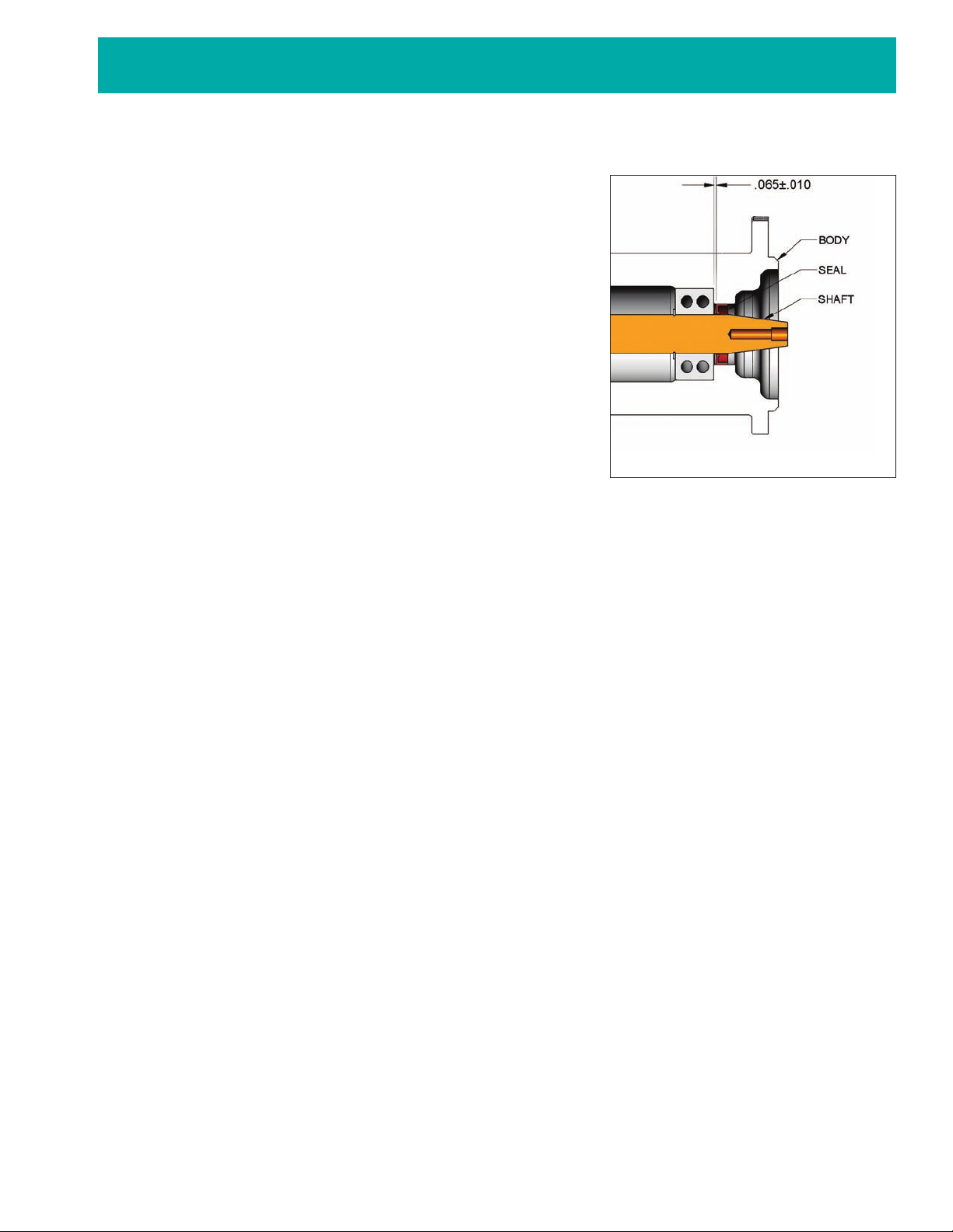
Caution: For the G22012-01, G22012X, G3001-01, G3001-02 and G3001X,
when pressing the lip seal in the body from the impeller end, the lip seal
should be pressed 0.065” plus/minus 0.010” past the furthest bearing
location. See detailed illustration. This position is critical to the perform-
ance of the oil seal since it needs to be placed slightly further than the
bearing, but not as far as the beginning of the taper. Failure to place the
seal at this location will cause the lip seal to contact the tapered portion
of the shaft which will cause premature lip seal wear. Care should also be
taken to ensure proper alignment of the lip seal to the pump body and
that the lip seal is uniformly pressed to prevent distortion.
B. Press the shaft and bearing assembly (21) into the pump body.
For the G22012-01, G22012X, G3001-01, G3001-02 and G3001X,
ensure that the lip seal will not wear on the tapered portion of the
shaft (see Caution above). Replace the slinger (23) on the shaft
between the mechanical seal position and the bearings.
C. For the G22012-01, G22012X, G3001-01, G3001-02, G3001X, slide
the bearing shield (20) into the pump body and against the inner bearing.
D. Using internal snap ring pliers, install the retaining ring (19) into the body.
E. Press the mechanical seal seat (14) into the housing (13) with the gray silicon carbide face toward the impeller.
Lubricate the outside of the seat boot with a water soluble lubricant or soapy water for easier assembly. Oil or
grease must not be used as it will prevent the rubber cup assembly from properly gripping the housing. The seat
should be inspected to ensure that the cup did not become partially dislodged during the assembly procedure.
F. Slide the housing over the shaft and body assembly. Fasten the four bolts (11) and lockwashers, and torque
them to 12-16 ft-lbs.
G. Replace the drive gear assembly. Slide the gear (15) on the shaft. Place the thrust washer (18) on the gear and
against the shaft. Place the lockwasher (17) on the bolt (16), and then apply Loctite #262 or equivalent to the
bolt. Fasten the bolt to the shaft and torque it to 36 ft-lbs.
H. Lubricate the internal rubber portion of the mechanical seal (10) with a water soluble lubricant or soapy water
and slide the seal onto the shaft with the silicon carbide portion of the mechanical seal toward the seal seat. Oil
or grease must not be used as it will prevent the mechanical seal from properly gripping the shaft.
I. Using external snap ring pliers, replace the retaining ring (9) on the shaft.
J. Install the pin (8) into the housing.
K. Install the wear plate (7) with the hole in the plate aligned with the pin in the housing.
L. Place the cam (6) in the housing. For the plastic cam halves, create the cam assembly by connecting the cam
halves (6) together. Align the hole in the cam with the pin in the housing and ensure the anti-rotation pin is in
place after the cam is fully installed.
M. Insert the impeller (5) in the housing using a twisting motion. Ensure that the impeller blades are bent in the
same direction as upon removal (counterclockwise when viewed from the cover). For ease of installation, apply
asilicon lubricant to the impeller.
Caution: DO NOTUSE A PETROLEUM-BASED LUBRICANT (petroleum product will cause damage to the
impeller).
N. Insertthe quad ring (4) into the groove,install the cover (3) on the housing, and then fasten the lockwashers (2)
and bolts (1). Torque the cover bolts to 5-8 ft-lbs.
O. After installation, inspect the seal, body, housing and cover for leaks.
Close-up Drawing of Lip Seal Area