MN301370 Rev B1 9 |
Safety Precautions Step Four
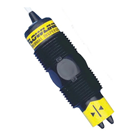
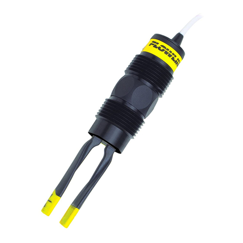
About Manual: PLEASE READ THE ENTIRE MANUAL PRIOR TO INSTALLING OR USING THIS
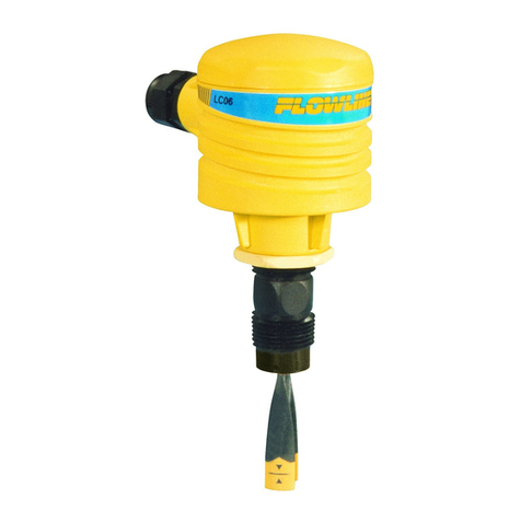
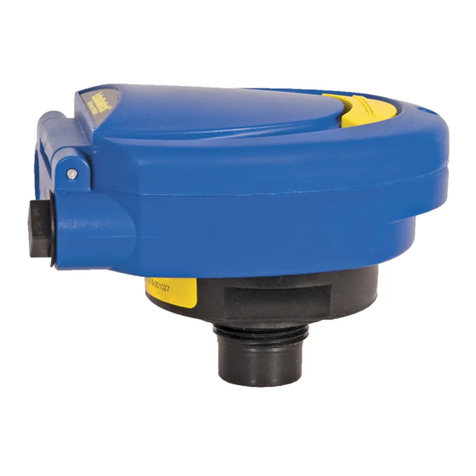
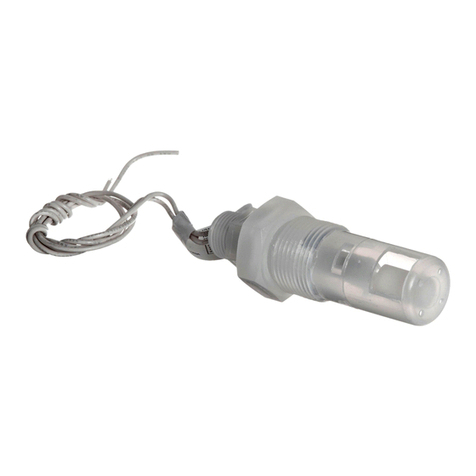
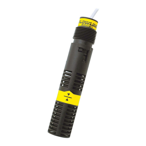
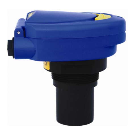
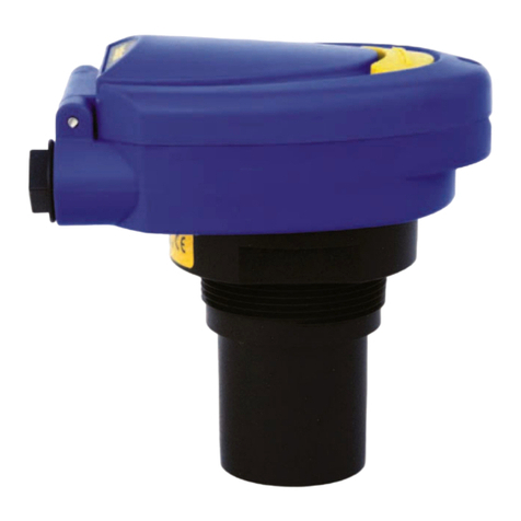
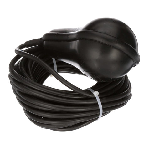
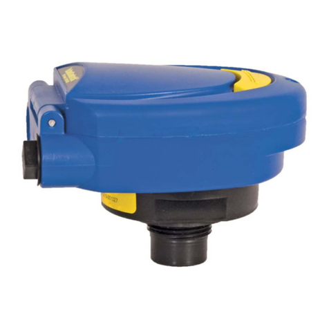
PRODUCT. This manual includes information on all models of Flowline Switch-Tek™ Powered Level
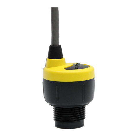
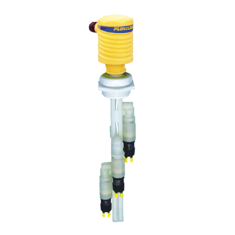
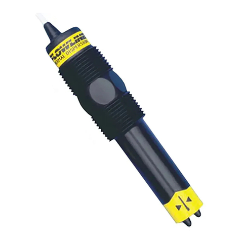
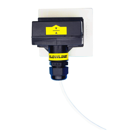
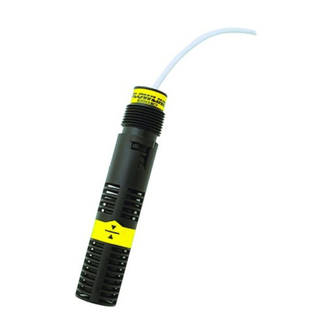
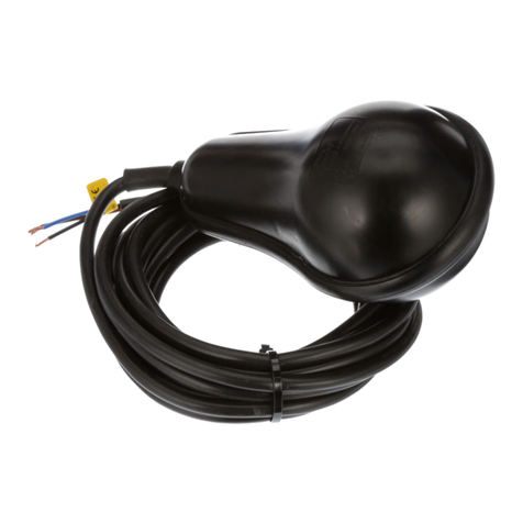
Switches: LZ12, LU10, LP15 and LO10 series. Please refer to the part number located on the sensor label
to verify the exact model which you have purchased.
User’s Responsibility for Safety: Flowline®manufactures a wide range of liquid level switches and
technologies. While each of the these switches are designed to operate in a wide variety of applications, it
is the user’s responsibility to select a switch model that is appropriate for the application, install it properly,
perform tests of the installed system, and maintain all components. The failure to do so could result in
property damage or serious injury.
Proper Installation and Handling: Because this is an electrically operated device, only properly trained
staff should install and/or repair this product. Use a proper sealant with all installations. Note: Always
install the 3/4” Viton gasket with all versions of Switch-Tek™ with metric threads. The G threaded version
will not seal unless the gasket is properly installed. Never over tighten the sensor within the fitting, beyond
a maximum of 80 inch-pounds torque. Always check for leaks prior to system start-up.
Material Compatibility: The LU10 and LO10 series sensors are available in two different wetted materials.
Models L_10-1__5 are made of Polypropylene (PP). Models L_10-2__5 are made of Perfluoroalkoxy
(PFA). The LZ12 series is made of made of Ryton® (40% glass filled) and the LP15 series is made of PP.
Make sure that the model you have selected is compatible with the application liquid. To determine the
chemical compatibility between the sensor and its application liquids, refer to an industry reference such as
the Compass Corrosion Guide (available from Compass Publications).
Wiring and Electrical: The supply voltage used to power the sensor should never exceed a maximum of
36 volts DC (30 VDC for LZ12 series). Electrical wiring of the sensor should be performed in accordance
with all applicable national, state, and local codes.
Flammable, Explosive and Hazardous Applications: Only the LU10-___5 series switch is rated for use
in hazardous locations. Refer to the Certificate of Compliance for all applicable intrinsically safe ratings
and entity parameters. Refer to the National Electric Code (NEC) for all applicable installation
requirements in hazardous locations. DO NOT USE THE LZ12, LP15 OR LO10 SERIES GENERAL
PURPOSE SWITCH IN HAZARDOUS LOCATIONS.
Warning
The rating for the relay is 60 VA (125 VAC max / 1A max). Flowline’s Switch-Tek™ level switches are not
recommended for use with electrically charged application liquids. For most reliable operation, the liquid
being measured may need to be electrically grounded. Always install the 3/4” Viton gasket with all versions of
the powered sensors with metric threads. The G threaded version will not seal unless the gasket is installed
properly.
MAKE A FAIL-SAFE SYSTEM
Design a fail-safe system that accommodates the possibility of switch and/or power failure. FLOWLINE
recommends the use of redundant backup systems and alarms in addition to the primary system. Adding a
redundant high level float switch to the system is a cost effective means to prevent costly tank overflows.
Switch-Tek™ level and leak switches have a single internal relay. The normally open (NO) or normally closed
(NC) operation is user selected based on the desired system control. Always design a fail-safe system that
accommodates for the possibility of functional and/or power failure to the instrument. The "normal" relay state
is where the relay coil is de-energized and the relay indicator is OFF. Therefore, if power is cut OFF to the
switch it will de-energize the relay. Make sure that the de-energized state is the safe state in your system
design. As such, if switch power is lost, a pump will turn OFF if it is connected to the normally open side of the
relay.
