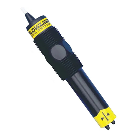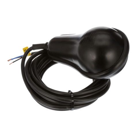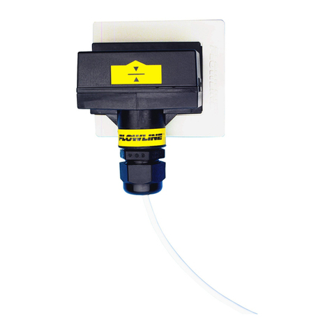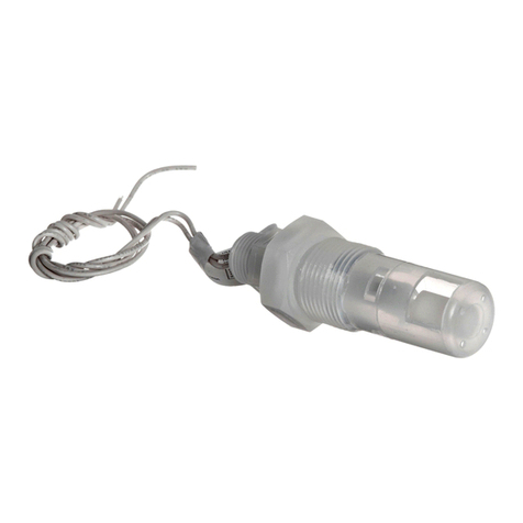
SAFETY PRECAUTIONS
Step Two
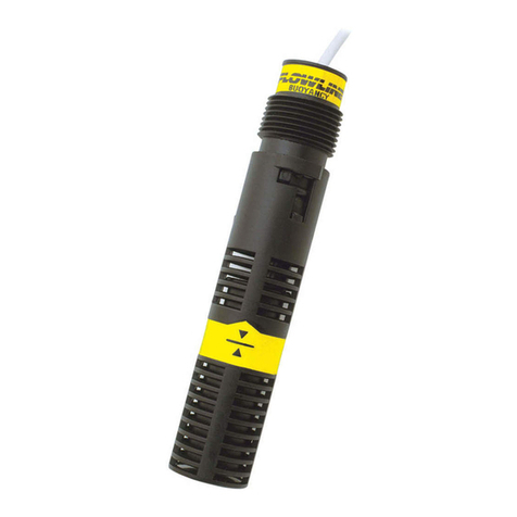
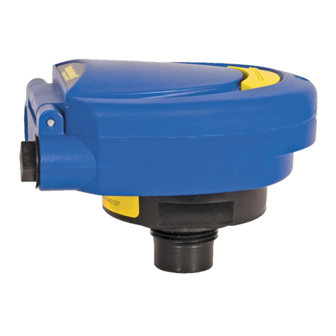
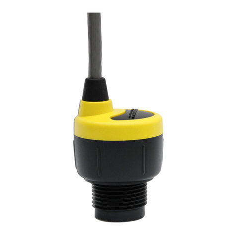
About this Manual:
PLEASEREADTHEENTIREMANUALPRIORTOINSTALL-
INGORUSINGTHISPRODUCT.Thismanualincludesinforma-
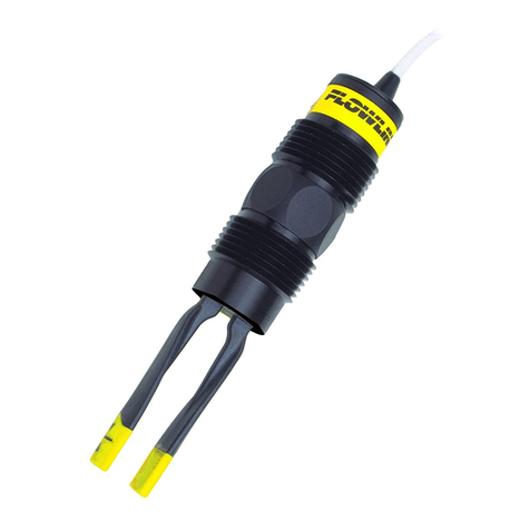
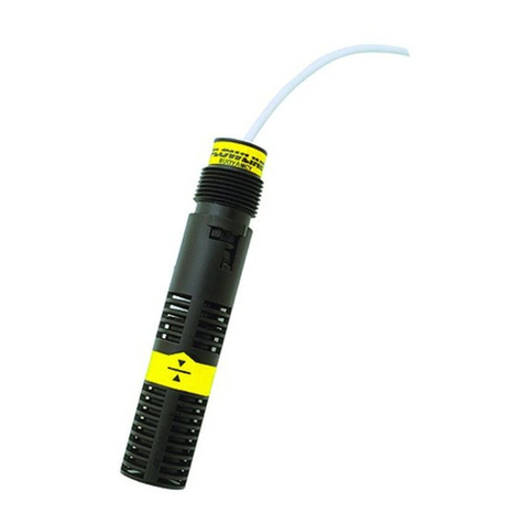
tionon all modelsof Intrusive RFCapacitance level switchesfrom
Flowline, LP10 series. Please refer to the part number located on
the switch label to verify the exact model which you have pur-
chased.
User’s Responsibility for Safety:
Flowline manufactures a wide range of liquid level sensors and
technologies. While each of these sensors is designed to operate in
awidevarietyofapplications,itistheuser’sresponsibilitytoselect
a sensor model that is appropriate for the application, install it
properly, perform tests of the installed system, and maintain all
components. The failure to do so could result in property damage
or serious injury.
Proper Installation and Handling:
Use a proper sealant with all installations. Never overtighten the
sensor within the fitting, beyond a maximum of 80 inch-pounds
torque. Always check for leaks prior to system start-up. Do not
install the LP10 series sensor within 6" of any metal.
Material Compatibility:
The LP10 series sensor is available in two different wetted materi-
als. Models LP10-1___ are made of Polypropylene (PP). Models
LP10-2___ are made of Perfluoroalkoxy, also known by the trade
name Teflon, (PFA). Make sure that the model you have selected
is compatible with the application liquid. To determine the chemi-
cal compatibility between the sensor and its application liquids,
refertoanindustryreferencesuchastheCompassCorrosionGuide
(available from Compass Publications, phone 619-589-9636).
Wiring and Electrical:
The supply voltage used to power the LP10 series sensor should
never exceed a maximum of 36 volts DC. Electrical wiring of the
sensor should be performed in accordance with all applicable
national, state, and local codes.
Flammable,ExplosiveandHazardousApplications:
Only the LP10-___0 series switch is rated for use in hazardous
locations. Refer to the certificate of Compliance for all applicable
intrinsically safe ratings and entity parameters for the LP10-___0.
Refer to the National Electric Code (NEC) for all applicable
installation requirements in hazardous locations. DO NOT USE
THE LP10-___2, LP10-___3 or LP10-___5 GENERAL PUR-
POSE SWITCH IN HAZARDOUS LOCATIONS.
WARNING
DonotinstalltheLP10levelswitchonametallictank,
or within 6" of any metallic object. Metal will ad-
verselyaffect thedielectric sensitivityof thesensor.
ThemaximumcurrentdrawontheFETswitchis100mA.
Flowline’sLP10seriessensorsarenotrecommended
forusewithelectrically charged applicationliquids.
For the most reliable operation, the liquid being
measured will need to be electrically grounded.
INTRODUCTION
Step Three
About Intrusive RF Capacitance Technology:
Flowline’sLP10seriesgeneratesa300kHzpulse-waveradiofrequency
signal from the capacitance electrode located in the sensing tip of each
sensor. When liquid comes into contact with the sensing tip, the
capacitance as measured by the sensor changes based on the dielectric
constant of the liquid. Flowline’s sophisticated electronics convert the
capacitance value into a simple two-wire, 4 or 20 mA, a three-wire FET
switchoutputwhichindicateswhetherthesensoriswetordryora4-wire
NO or NC 1A relay output. In the dry state, the sensor delivers a two
wire,5mAsignal output.Inthe wetstate,the sensordeliversa twowire,
19 mA signal output.
The sensor’s operation may vary based on the dielectric properties of
variousapplicationliquids. TheLP10series sensorisfactory-calibrated
to be used with liquids with a dielectric value between 20 and 80. For
example, if the application liquid is acetal (with a dielectric constant of
about 3.6), the sensor (as factory calibrated) will not detect its presence
when it is wet. However, if the application liquid is glycol (with a
dielectric constant of about 35) the sensor will reliably detect its
presence when wet.
Warning: Do not install the LP10 series sensor within 6 inches of any
metallic object. Metal will adversely affect the dielectric sensitivity of
the sensor.
Flowline’s LP10 series sensors are not recommended for use with
electricallycharged application liquids.Formost reliable operation,the
liquid being measured may need to be electrically grounded.
Acetone 21
Acetoaldehyde 22.2
Acetyl methyl hexyl
ketone 28
Alcohol 16 to 31
Ammonia 15 to 25
Acetic acid 4.1 to 6.2
Butyl chloride 9.6
Barium chloride 9 to 11
Benzene 2.3
Benzine 2.3
Barium nitrate 5.6
Bromine 3.1
Chlorobenzene 4.7 to 6
Chlorotoluene 4.7
Chloroform 4.5 to 5.0
Chlorine, liquid 2.0
Carbon tetrachloride 2.2
Cyan 2.6
Cyclohexane methanol3.7
D.I. Water 20
Ethyl toluene 2.2
Ethyl alcohol 23
Ethylene glycol 37
Ethylene oxide 14
N-butyl formate 2.4
Nitrobenzene 26 to 35
Nitrotoluene 25
Naphthalene 2.3 to 2.5
Oils, vegetable 2.5 to 3.5
Oils, mineral 2.3 to 2.4
Oils, petroleum 1.8 to 2.2
Oleic acid 2.5
Propane, liquid 1.8 to 1.9
Potassium nitrate5.0 to 5.9
Potassium chloride 5.0
Stearic acid 2.3
Toluene 2.4
Trichloroethylene 3.4
Trichloroacetic acid 4.5
Terephthalic acid1.5 to 1.7
Thinner 3.7
Urea 3.5
Vinyl chloride 2.8 to 6
Vinyl alcohol 1.8 to 2.0
Water, 20°C80
Water, 100°C48
Ethylene dichloride
11 to 17
Ethylene chloride 10.5
Ethyl acetate 6.4
Ethyl salicylate 8.6
Ethyl stearate 2.9
Ethyl silicote 4.1
Formic acid 59
Ferric oleate 2.6
Freon 2.2
Glycerine 47
Glycol 30
Glycol nitrite 27
Gasoline 2 to 2.2
Hydrochloric acid 4.6
Isobutyric acid 2.7
Isobutyl methyl ketone 13
Jet fuel 1.7
Lead carbonate 18
Lead nitrate 38
Methyl salicylate 9.0
Methanol 33
Methyl alcohol 33 to 38
Margarine, liquid2.8 to 3.2
Methyl acetate 7.3
Table of Common Dielectric Constants
NOTE: Liquids with a dielectric constant less than 20 will not be
detected by an LP10 series sensor, as factory calibrated.
