manuals.online logo
Brands
  1. Home
  2. •
  3. Brands
  4. •
  5. FlowLine
  6. •
  7. Switch
  8. •
  9. FlowLine LV42 Series Installation and operating instructions

FlowLine LV42 Series Installation and operating instructions

When making the connections described above, ensure that the
maximum motor power does not exceed the values indicated on
the level switch. The power supply cable is an important part of the V42 Series.
Should the cable appear to be damaged, discontinue use immediately and proceed
to replace the unit. The yellow/green wire found on some units is the ground wire
and must be connected to a suitable ground terminal with the dimension greater
than 1mm2.The terminal used must also be protected against accidental break.
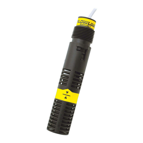
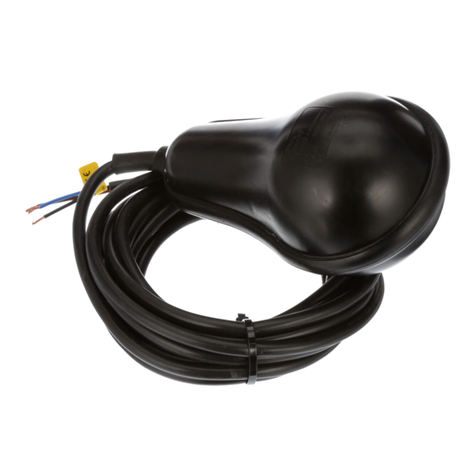
Th LV42 S ri s Larg Float L v l Switch is a mercury-free self counterweighted
floating switch designed for the automation of pumps, specifically filling and draining
of tanks, wells, and reservoirs. The V42 Series body is free of any irregularities
making it ideal for use in sewage water applications. The polypropylene body
consists of a double airtight chamber with high-pressure melted polypropylene re-
injection sealing to ensure a perfect seal against infiltration. Cable hangers are
available to suit a variety of mounting applications. Featuring CE approval, high
temperature durability, oil resistance, and drinking water suitability.
INSTALLATION
The basic operating principle of the V42 Series is very simple. As fluid level rises
the micro-switch located inside the V42 Series is counter-balanced in such a way
that it generates a flipping action in the position of the switch. When fluid level
decreases the float starts in an inverted state then positions correctly. This change
in position generates a signal that can be used to actuate a motor or signal an
indicator alarm. To ensure the proper function of the V42 Series, it is necessary to
secure the electric cable inside the tank or well as illustrated in Figure 1. The length
of the cable measured between the fixture point and the body of the V42 Series
should be a minimum of 6 in (15 cm). It is essential to ensure that there are no
obstructions in the V42 Series operational area before operation. During
operation, adjustm nts to th LV42 S ri s cabl must not b mad und r any
circumstanc s, due to the fact that any unwanted cable connections made while
the V42 Series is immersed in water can lead to electric shock.
There is a hanging bracket accessory option available ( V49-9000), for wire
arrangement. The bracket allows the cable of the V42 Series to be held in place
at the top of the tank.
Not : The V42 Series is self counterweighted and can be used without the need
of additional counterweight, clamp, or bracket. The previous are means to simplify
installation and aid in organizing the use of multiple float switches.
ELECTRICAL CONNECTIONS
SPDT, single pole double throw allows for operation of both increasing and
decreasing level, depending on the connections made between the terminals of the
micro-switch and the cable. SPDT, a three-conductor cable (without ground
option), has one lead that is common, one that is normally open (NO), and the
other that is normally closed (NC), for the proper connections of these conductors
please refer to the wiring diagrams in Figures 2 and 3.
SPECIFICATIONS
S rvic : Compatible liquids, slurries.
W tt d Mat rials:
Housing: Polypropylene;
Cable: PVC.
Op rating T mp ratur : -4 to 122°F (-20 to 50°C).
Pr ssur Limits: 29 psi (2 bar).
Enclosur Rating: IP68.
Switch Typ : SPDT.
El ctrical Rating: 10 (3) A @ 250 VAC.
Mounting Ori ntation: Vertical.
Shipping W ight:
Housing: 2.4 lb (1100 g);
Cable: 0.77 oz (21.27 g) per foot.
Ag ncy Approval: CE.
4-45/64
[119.50] 4-23/64
[110.83]
8-23/64
[212.50]
5/8
[16.00]
Bracket
LV49-9000
Figur 1: Installation
NOTICE
Switch-T k LV42 S ri s Larg Float Switch
Sp cifications - Installation and Op rating Instructions
LV42 S ri s Quick Start
QS300210 Rev A
 
1
%*)#///$'*/'&)#"*(
!0#(!&''#.#'+*'-,&*)+$'*/'&)#"*(
BROWN
BLACK L
N
COM
N.O.
N.C.
BLUE
BROWN
BLACK L
N
COM
N.O.
N.C.
BLUE
Figur 2-Doubl Function (Emptying (NO)) Figur 3-Doubl Function (Filling (NC))
3 x 1 CABLE
WIRING DIAGRAMS
©Copyright 2012 Flowline, Inc. Printed in U.S.A. 10/12 QS300210 Rev A
 
1
%*)#///$'*/'&)#"*(
!0#(!&''#.#'+*'-,&*)+$'*/'&)#"*(
F r c mplete pr duct d cumentati n, vide training, and technical supp rt, g t www.fl wline.c m.
F r ph ne supp rt, call 562-598-3015 fr m 8am t 5pm PST, M n - Fri.
(Please make sure y u have the Part and Serial number available.)
Warranty
Flowline warrants to the original purchaser of its products that such products will be free from defects in material and workmanship under normal use and service in accordance
with instructions furnished by Flowline for a period, which is equal to the shorter of one year from the date of purchase of such products or two years from the date of
manufacture of such products. Flowline's obligation under this warranty is solely and exclusively limited to the repair or replacement, at Flowline's option, of the products or
components, which Flowline's examination determines to its satisfaction to be defective in material or workmanship within the warranty period. Flowline must be notified
pursuant to the instructions below of any claim under this warranty within thirty (30) days of any claimed lack of conformity of the product. Any product repaired or replaced
under this warranty will be warranted only for the remainder of the original warranty period.
R turns
Products cannot be returned to Flowline without Flowline's prior authorization. To return a product that is thought to be defective, go to www.flowline.com, and submit a customer
return (MRA) request form and follow the instructions therein. All warranty and non-warranty product returns to Flowline must be shipped prepaid and insured. Flowline will not
be responsible for any products lost or damaged in shipment.
Limitations
This warranty does not apply to products which: 1) are beyond the warranty period or are products for which the original purchaser does not follow the warranty procedures
outlined above; 2) have been subjected to electrical, mechanical or chemical damage due to improper, accidental or negligent use; 3) have been modified or altered; 4) anyone
other than service personnel authorized by Flowline have attempted to repair; 5) have been involved in accidents or natural disasters; or 6) are damaged during return shipment
to Flowline. Flowline reserves the right to unilaterally waive this warranty and dispose of any product returned to Flowline where: 1) there is evidence of a potentially hazardous
material present with the product; or 2) the product has remained unclaimed at Flowline for more than 30 days after Flowline has dutifully requested disposition. This warranty
contains the sole express warranty made by Flowline in connection with its products. A IMP IED WARRANTIES, INC UDING WITHOUT IMITATION, THE WARRANTIES
OF MERCHANTABI ITY AND FITNESS FOR A PARTICU AR PURPOSE, ARE EXPRESS Y DISC AIMED. The remedies of repair or replacement as stated above are the
exclusive remedies for the breach of this warranty. IN NO EVENT SHA F OW INE BE IAB E FOR ANY INCIDENTA OR CONSEQUENTIA DAMAGES OF ANY KIND
INC UDING PERSONA OR REA PROPERTY OR FOR INJURY TO ANY PERSON. THIS WARRANTY CONSTITUTES THE FINA , COMP ETE AND EXC USIVE
STATEMENT OF WARRANTY TERMS AND NO PERSON IS AUTHORIZED TO MAKE ANY OTHER WARRANTIES OR REPRESENTATIONS ON BEHA F OF F OW INE.
This warranty will be interpreted pursuant to the laws of the State of California. If any portion of this warranty is held to be invalid or unenforceable for any reason, such finding
will not invalidate any other provision of this warranty.

Other FlowLine Switch manuals

FlowLine Switch-Pro AU18 Series User manual

FlowLine

FlowLine Switch-Pro AU18 Series User manual

FlowLine LP50 Series User manual

FlowLine

FlowLine LP50 Series User manual

FlowLine EchoSwitch LU78 Series User manual

FlowLine

FlowLine EchoSwitch LU78 Series User manual

FlowLine EchoSwitch LU71 User manual

FlowLine

FlowLine EchoSwitch LU71 User manual

FlowLine LV10 Series User manual

FlowLine

FlowLine LV10 Series User manual

FlowLine EchoSwitch LU74-5004 User manual

FlowLine

FlowLine EchoSwitch LU74-5004 User manual

FlowLine Switch-Tek LV30 Series User manual

FlowLine

FlowLine Switch-Tek LV30 Series User manual

FlowLine Switch-Tek LZ12 Series User manual

FlowLine

FlowLine Switch-Tek LZ12 Series User manual

FlowLine Thermo-Flo FT10 User manual

FlowLine

FlowLine Thermo-Flo FT10 User manual

FlowLine Switch-Tek LV20-1201 User manual

FlowLine

FlowLine Switch-Tek LV20-1201 User manual

FlowLine EchoSwitch LU77 Series User manual

FlowLine

FlowLine EchoSwitch LU77 Series User manual

FlowLine Thermo-Flow FT10-1305 User manual

FlowLine

FlowLine Thermo-Flow FT10-1305 User manual

FlowLine LP10 Series User manual

FlowLine

FlowLine LP10 Series User manual

FlowLine 52 Series User manual

FlowLine

FlowLine 52 Series User manual

FlowLine 53 Series User manual

FlowLine

FlowLine 53 Series User manual

FlowLine Switch-Tek LZ12 Series User manual

FlowLine

FlowLine Switch-Tek LZ12 Series User manual

FlowLine Switch-Tek LV10-1301 User manual

FlowLine

FlowLine Switch-Tek LV10-1301 User manual

FlowLine EchoPod DL10 Series User manual

FlowLine

FlowLine EchoPod DL10 Series User manual

FlowLine Smart Trak AU18-4343 User manual

FlowLine

FlowLine Smart Trak AU18-4343 User manual

FlowLine Switch-Tek LV41 Series User manual

FlowLine

FlowLine Switch-Tek LV41 Series User manual

FlowLine EchoSwitch LU74 Series User manual

FlowLine

FlowLine EchoSwitch LU74 Series User manual

Popular Switch manuals by other brands

LevelOne FSW-1609TFX Specifications

LevelOne

LevelOne FSW-1609TFX Specifications

Titan HUB-1600I-RM user manual

Titan

Titan HUB-1600I-RM user manual

HP A5120 EI Series Configuration guide

HP

HP A5120 EI Series Configuration guide

Emerson Rosemount 2521 Series quick start guide

Emerson

Emerson Rosemount 2521 Series quick start guide

HP ProCurve 8100fl Installation and getting started guide

HP

HP ProCurve 8100fl Installation and getting started guide

Digital Equipment EtherWORKS Switch 8T/TX Installation and configuration

Digital Equipment

Digital Equipment EtherWORKS Switch 8T/TX Installation and configuration

Dell PowerConnect W-IAP175P Supplement

Dell

Dell PowerConnect W-IAP175P Supplement

rotork SS Safety manual

rotork

rotork SS Safety manual

Omega Engineering FSW-50 Series manual

Omega Engineering

Omega Engineering FSW-50 Series manual

H3C S7500 Series Operation manual

H3C

H3C S7500 Series Operation manual

Edimax ES-5224RM datasheet

Edimax

Edimax ES-5224RM datasheet

CIT KVM-8-4K user manual

CIT

CIT KVM-8-4K user manual

Quidway S3000 Series Operation manual

Quidway

Quidway S3000 Series Operation manual

NETGEAR GS728TXS installation guide

NETGEAR

NETGEAR GS728TXS installation guide

LevelOne GEL-1072 Brochure & specs

LevelOne

LevelOne GEL-1072 Brochure & specs

Gefen EXT-DVI-441N user manual

Gefen

Gefen EXT-DVI-441N user manual

EnGenius EWS2910P-FIT quick start guide

EnGenius

EnGenius EWS2910P-FIT quick start guide

TRENDnet TPE-80WS - Web Smart PoE Switch Specifications

TRENDnet

TRENDnet TPE-80WS - Web Smart PoE Switch Specifications

manuals.online logo
manuals.online logoBrands
  • About & Mission
  • Contact us
  • Privacy Policy
  • Terms and Conditions

Copyright 2025 Manuals.Online. All Rights Reserved.