FLUIDX XTR-96 User manual

XTR-96
96 Tube Rack Scanner
Manual
Version 2.205

August 2006
1

Index
Index .........................................................................................................................2
Welcome...................................................................................................................3
Introduction..............................................................................................................4
Installation................................................................................................................5
Getting started .........................................................................................................7
Running XTR-96.....................................................................................................11
Results configuration............................................................................................15
System settings .....................................................................................................19
Using the Winsock interface.................................................................................21
Setting up a ‘HyperTerminal’ session..................................................................23
Trouble shooting....................................................................................................25
2

Welcome
The XTR-96 Reader is the latest member of a family of sophisticated 2D Data Matrix code
readers capable of reading standard 96 way racks of pre coded tubes from a variety of
manufacturers provided that they adhere to the ISO 16022 Data Matrix Two Dimensional
Bar Code format. The software has been designed to run with the minimum of user input
and set-up.
Designed and Manufactured for:
fluidX Ltd
Unit 6
Monks Heath Hall Workshops
Chelford Road
Nether Alderley
Macclesfield
Cheshire
SK10 4SY
Tel: +44 1625 861 614
Fax: +44 1625 861 615
Email: [email protected]
.
3

Introduction
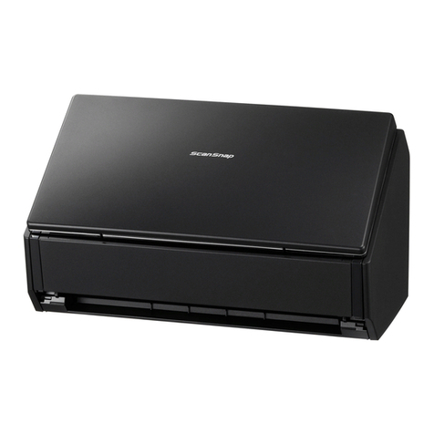
The XTR-96 is a high performance reader of SBS format racks containing industry standard
coded tubes. It is based upon a specially modified flat bed scanner with a USB2 interface
delivering high speed operation. As the system uses a unique method of operation and
algorithms that do not rely on custom chips, the decode speed and overall performance is
directly related to the power of the PC that is running the software.
XTR-96 Features
Flexible software integration -The system has a standard Windows™ interface with an
automation override facility. Several methods are available for the controlling application to
collect the processed results.
The Windows based software is based upon Medusa™ decode algorithms for high speed
and reliability.
Full Industry standard ODBC compatibility with common database systems.
Images of the tubes are displayed after every read cycle together with the standard SBS grid
references 1 – 12 and A - H.
An integrated database allows easy verification of tube data.
4

Installation
Before you start please ensure that you have the
•XTR-96 Reader
•Power Supply and Lead
•USB Cable
•USB Dongle
•XTR-96 Software CD-ROM
Unlock the Scanner by placing a small screw driver into the slot at the read and moving the
slider switch to the right (towards the USB and Power connectors) see below.
Un-lock
Illustration showing rear of unit.
Do not connect USB Cable or USB Dingle at this stage.
Insert CD-ROM and follow on screen instructions.
1. Install should start automatically, if not start the install manually by double clicking on
the setup.exe icon.
2. Click Next
5

3. Select Fujitsu fi-60F as the scanner type.
4. Restart the computer to complete the installation process.
5. Connect the USB dongle and USB Scanner Cable.
6

Getting started
This section assumes that the software has been loaded, your scanner is turned on
and that you have a rack of coded tubes placed on the scanner.
You can execute the XTR-96 software from either the start button or from the shortcut that
was created on you desktop.
To execute from the start menu, single click the left mouse button on the start button
and select Programs then move to the entry that says XTR-96 finally move to the entry that
says XTR-96 and single click the left mouse button.
To execute from the desktop shortcut simply locate the shortcut on your desktop that says
XTR-96 and double click the left mouse button.
Once you have done this you will see the following screen.
The software is now starting.
7

After a few second this screen will be displayed.
This screen is displayed on the first execution of the software, the software will automatically
scan and a progress bar will be shown as in the screenshot above (ensure that FUJITSU fi-
60F is the scanner selected).
In the screen shot above you will see an image of what the scanner has captured. You will
notice a yellow box with a square at each of its four corners. This box should be aligned with
each of the corners of the rack containing the tubes.
If it is not aligned use the mouse to point to one of the yellow boxes that is not on the corner
of the rack, left click the mouse and drag the yellow box until it is over the corner of the
rack that it was nearest to. Repeat this operation until all four yellow boxes are on the
corresponding corners of the rack.
Before we leave this screen please make sure the correct tube manufacturer has been
selected. You can change tube manufacturer by simply left mouse button clicking the
radio button that is to the left of the tube manufacturer’s name. This section is located to
the right of centre and towards the bottom of the dialog box the section is tilted “Tube
manufacturer”.
We will explain about the other settings on this screen later in this manual. Please left
mouse click the OK button located at the bottom of the dialog box to save and exit.
8

The system will now scan again, this time it will only scan the area that was within the yellow
box that you have just configured.
Once the scan has completed the screen display should look like this:
The green boxed grid of 12 columns and 8 rows should surround each of the 96 coded
tubes. If the grid is not correctly aligned then in the same way that we moved the yellow box,
move the green grid by left mouse clicking and dragging it by its corners. Once each tube
is located centrally in its own box you can then left mouse click the Save ROI button.
ROI is an acronym for Region of Interest.
Once the ROI has been saved we can select one of the other functions from this dialog. If
we left mouse click the Decode button the software will decode the 96 coded tubes from
the image that is currently displayed.
Alternatively we can left mouse click the Scan and Decode button, this will start a new
scan and when the scan had finished it will have decoded the 96 coded tubes.
9

You should now have a screen that looks very similar to the one that is shown above. The
one above has tube A1 missing and the progress bar and decode results in the bottom left
hand corner of the screen shows that we have 95 tubes OK and one that has failed. There
are lots of other buttons on this screen which will come back to later. Now move the mouse
to white text entry box called Rack ID: left mouse click inside the white box area and
type in the Rack ID that is on the rack barcode, if it does not have one just type test. Now
left mouse click the OK button to the right hand side of this dialog.
This concludes the first execution of the XTR-96 Software this sets up the system ready for
use. Now left mouse click the Exit button on the bottom right hand corner of the main
screen.
10

Running XTR-96
Once you have started the XTR-96 software as described in the getting started section of
this manual you will see the following screen.
To scan a rack of tubes place the rack in the scanner housing and left click the mouse on
the Scan and Decode button, the software will now perform a scan of the rack and then
decode image of coded tubes.
11

The software will now display a screenshot similar to the one above. As you move the
mouse pointer over the tubes a small text box indicates the cell ID and the tube number, you
will also see that the row and column numbers highlighted.
If you left mouse click the Zoom In button the screen will magnify and you will see the
image in more detail.
12

This is a screen shot of a zoomed image.
The Min Zoom / Max Zoom button zoom has two effects, in Min Zoom mode it shows the
whole rack of tubes in the Max Zoom mode it shows two tubes.
The Zoom In and Zoom Out buttons progressively reduce, or enlarge, the image between
minimum and maximum zoom positions.
Now move the mouse to white text entry box called Rack ID: left mouse click inside the
white box area and type in the Rack ID that is on the rack barcode. Now left mouse click
the OK button to the right hand side of this dialog to save the decoded data to the results
files (see Results Configuration, later).
13

We are now going to take a look at some of the other features of the software.
Move the mouse pointer to the file menu and left click the mouse, you will see a list of
commands some of which are grey in colour and some that are black.
14

Results configuration
From the main screen select Settings / Results to display the screen above.
This screen is used to define the names and storage location of the results files, the
structure of the data in the results files and provides connectivity to an external database
using the industry ODBC standard.
By default XTR-96 saves two copies of decoded data: once in a file with an unchanging
name, known as the “OLE Link File” and once in a file with a configurable name composed
of nine independent elements.
15

The File Naming panel allows the various elements to be activated, or suppressed at will.
The elements are:
•A constant prefix, comprising
characters of the user’s choice
•A suffix, which normally be .txt to
indicate a text file, or .csv to indicate
a comma separated variable file.
Windows associates suffices with
applications; thus, if Excel is
installed on the PC when a .csv file
is double clicked in Windows
Explorer Excel is automatically
started and a spreadsheet is created
and populated with data from the
.csv file. This provides a convenient
way of viewing the data, or carrying
out further processing. Double
clicking a .txt file would normally
open the file in Notepad, which does
not present the data in such a
convenient way.
•A sequence number of a specified
length which starts with a defined
value when XTR-96 is started, or will
continue from the last number used
irrespective of restarts. The
sequence number is incremented
each time a rack is read.
•A user defined Scanner ID.
•A user defined Scanner location
•A rack identifier, which could be a barcoded serial number on the rack read.
•The date and / or time the rack was read.
The “Example Filename” field shows what the filename will look like with the options
currently defined.
It is possible to select only unvarying elements to make up the name, in which case the
second time a rack is read a duplicate file name will be generated and a warning will be
issued.
16

The Results Destination panel allows the setting of:
•The storage path for data - this is the name of the
folder where all generated data is saved.
•OLE Link File - a fixed name file where the last set
of results are saved. Any old data will be
overwritten. The file name may be changed from the
default, but is always saved in a folder called “OLE
Link” below the storage path already defined.
•ODBC Dataset Name - Activation of this check box
will cause data will to be sent to the database at the
end of each reading cycle. The connection to the
database is made by specifying an ODBC Dataset
Name (DSN), which will be given to you by your
system administrator.
The database can reside on the reader PC, or on a remote, networked machine. XTR-
96 comes with a preconfigured demonstration local Access database. It is normally
recommended that data should be saved on a professional data system, eg SQL Plus or
Oracle, mounted on a remote machine. (It has been found that using a data base on the
local machine leads to poor performance as data volumes increase, especially if an
Access database is used, which is not optimised for handling large volumes of data.
Tube Labels are fixed strings of characters added to the front and / or end of the each tube
code. These may be specified as Prefix and Suffix, respectively.
17

Header Information - a number of lines of control information may be specified at the top of
each results file:
•Date and Time - when checked this will cause the
date and time of the read cycle to be inserted at the
top of the results file.
•Location of the scanner - the scanner location
entered in the File Naming Section will be used. If
you do not want the scanner location used in the
filename: you should check the filename scanner
location, type in required scanner location and then
uncheck the scanner location.
•File name - The name of the file will be added to
the lines of header information.
•Rack ID - Use the RackID which was input at
reading time
•Free Text - Two lines of information of the user’s choice.
Results Format - allows the presentation of the results to be modified:
•Values Reported - tube IDs (the code printed on the tube)
may be associated with their x/y positions in the rack (eg
B5), or the IDs may be used on their own.
•Spacing of Results - an optional number of spaces may
be prefixed to each result line and results may be delimited
by commas, or by a comma and a space.
•Separation of Records - all results may be printed on the
same line, or a new line can be used for each result.
•Grouping of records - allows the results the be printed
row by row, or column by column.
18

System settings
From the main screen select Settings / System to display the dialog shown above.
This will enable the following groups of activity to be configured:
Winsock settings:
•The hostname of the PC is displayed in the title bar of this section and is needed
when configuring a client Winsock session to interface with XTR-96.
•Check Enable to activate the Winsock interface.
•The default Port Number (201) may be changed if, for example, you have another
system that uses Port Number 201. It is not usually necessary to change this value,
which is needed when configuring a client Winsock session to interface with XTR-96.
•Add CRLF to Winsock data - this is essentially cosmetic. When viewing a
HyperTerminal session (see later) data tends to be shown in a continuous stream of
values across the screen and is not easy to interpret (this causes no problem to an
application which knows how much data to expect). By checking this field each item
of data is left justified on the next line of the screen and creates a clear display of the
Winsock transactions.
•Include data count with transmitted data - some of the transactions generate
more data than can be transmitted in a single Winsock block of data. Sometimes it
can be useful in a client application to know, at the start of transmission, how much
data is going to be transmitted. When this feature is enabled the first block of data is
preceded with a 16 character block comprising the number of characters to follow
right padded with spaces.
Scanner settings:
19
Table of contents
