FLUXWERX View Suspended Configuration guide

install
instruction
PAGE 1 of 4
Install-View | 2020-03
All rights reserved. © Fluxwerx Illumination 2020 604.549.9379 | fluxwerx.com
Due to continuous product improvements, specifications and dimensions are subject to change without notice. Certain options have
limited compatibility with some other product selections. Consult www.fluxwerx.com for most current technical information.
Tools:
• Level
• Sharp Side Cutter
• Measuring Tool
• Wire Stripper / Knife
• Phillips Screwdriver
TOOLS REQUIRED
Refer to Driver Enclosure Installation Documents
+ Row Configuration Document
Install ceiling driver enclosure and aircraft cable suspension per
appropriate ceiling type installation instructions — noting the fixture
spacing and that the non-power suspension point is NOT the end
suspension point.
1INSTALL CEILING DRIVER ENCLOSURE
Read Before Beginning Installation:
• Do not join fixture lengths together on the floor and lift into
place. This introduces significant forces on the joins and will
damage the fixtures.
• All fixtures should be installed in accordance with national and
local building and electrical codes.
• Leave the protective bag and care labels on the fixture during
installation. Warranty is void if labels are removed before
installation is complete.
• Support fixtures under the lower rail during handling.
IMPORTANT HANDLING
Lift from below
Leave bag and
care labels in place
Warranty void if removed
before installation
VIEW SUSPENDED

installation
PAGE 2 of 4
Install-View | 2020-03
All rights reserved. © Fluxwerx Illumination 2020 604.549.9379 | fluxwerx.com
Due to continuous product improvements, specifications and dimensions are subject to change without notice. Certain options have
limited compatibility with some other product selections. Consult www.fluxwerx.com for most current technical information.
Refer to Row Configuration Document
1. Lift first fixture section (or individual fixture if stand-alone) into place,
supporting it under the lower rail (NOT top rail).
2. Insert the aircraft cables into both ends of the fixture mounts.
3. Adjust height and level the fixture section. The aircraft cable gripper is
released by pressing down on the inner tube.
If stand-alone fixture, go to step #8.
For Joining Ends: Bend cable up and cut cable near exit point so cable does
not protrude out.
Trim aircraft cable to length (drop height from ceiling to top of fixture
+ 1.5") with a sharp side cutter, minimizing any frayed ends. Fixture can
accept a max. length of up to 2" of aircraft cable. Aircraft cable gripping
mechanism needs min. 1" aircraft cable inserted.
Lay the fixture sections out to ensure the correct sections with ends and
joints are supplied. Note that runs will have a Non-Power suspension
point located one point in from the end of the run. Ensure fixture sections
are laid out to match the Power suspension points that were prepared on
the ceiling.
1. Lift the next fixture section into position, supporting it underneath.
Insert an aircraft cable into the non-joining end to retain it, then slide
the joiner end into the previous fixture and press them together.
2. Level the end of the fixture by adjusting the aircraft cable in the gripper.
2TRIM AIRCRAFT CABLE 3LAY OUT LUMINAIRES
5CUT AIRCRAFT CABLE AT JOIN
4LIFT INTO POSITION + LEVEL
6JOIN FIXTURES + LEVEL
DROP HEIGHT + 1.5"
NOTE:
1. For Drywall and Surface ceiling types, feed the aircraft cable through
the canopy cover and threaded sleeve before inserting the cable into
the fixture mount.
2. Leave the protective bag on the fixture during installation.
view suspended

installation
PAGE 3 of 4
Install-View | 2020-03
All rights reserved. © Fluxwerx Illumination 2020 604.549.9379 | fluxwerx.com
Due to continuous product improvements, specifications and dimensions are subject to change without notice. Certain options have
limited compatibility with some other product selections. Consult www.fluxwerx.com for most current technical information.
1. Determine the length of cord required.
2. Cut off the excess.
3. Strip the jacket and wires.
4. Connect to the blue and red wires in the low voltage junction box.
NOTE: Depending on ceiling type, the canopy may need to be slid down the cord
to complete the low voltage wiring.
For T-bar ceilings: Close the wiring lid.
Using an allen key tool, tighten all 4 set screws at the joint until the
fixture joint is tight and secure (using supplied allen key tool).
Repeat steps #5, 6 + 7 with each fixture section.
NOTE: Do not adjust the Phillips head screws.
1. Clip fixture end of cord into the cord restraint, ensuring the black heat
shrink is below the top of the cord restraint.
2. Lift low-voltage power cord up to ceiling box and attach cord clips.
7SECURE JOINS 8ATTACH POWER CORD
10A T-BAR APPLICATIONS: CLOSE WIRING LID
9CONNECT TO J-BOX NOTE:
For VU1:
4 conductor cords have a red + blue stripe pair and a red + blue solid pair —
ensure the pairs are maintained in junction box connections.
• The solid pair connects to the 4 foot section of fixture nearest the cord.
• The striped pair connects the 4 foot section furthest from the cord.
• Connect the pairs to the appropriate driver circuit (for 2 circuit module, solid pair
is circuit 2, striped pair is circuit 1).
• If driver enclosure has only one pair of output wires, connect all red wires
together (3) and all blue wires together (3).
For VU3:
Independent Up|Dn Lighting Control: 4 conductor cords have a red + blue
stripe pair and a red + blue solid pair — ensure the pairs are maintained in
junction box connections.
• The solid pair connects to the direct lighting section of fixture (down).
• The striped pair connects to the indirect lighting section of the fixture (up).
• Connect the pairs to the appropriate driver circuit (solid pair is circuit 2
downlight, striped pair is circuit 1 uplight).
For drywall ceilings: Lift the canopy into place and tighten the sleeve.
10B DRYWALL APPLICATIONS: INSTALL CANOPY
view suspended

installation
PAGE 4 of 4
Install-View | 2020-03
All rights reserved. © Fluxwerx Illumination 2020 604.549.9379 | fluxwerx.com
Due to continuous product improvements, specifications and dimensions are subject to change without notice. Certain options have
limited compatibility with some other product selections. Consult www.fluxwerx.com for most current technical information.
For surface mount: Close the low voltage wiring lid, install the cover
assembly into place, and tighten the sleeve.
1. Leave the protective bag and care labels on the fixtures until
construction and furniture are complete.
2. Fixture can be operated as normal with the bag on.
3. Tear bag at perforation, do not use knives or tools.
12 REMOVE BAG LATER
10C SURFACE APPLICATIONS:
INSTALL COVER ASSEMBLY
1. Stretch the cord up and reset the cord clips to hold the cord inline with
the aircraft cable.
2. Apply power to the driver circuit(s).
11 SECURE CORD + APPLY POWER
view suspended
Popular Light Fixture manuals by other brands

American DJ
American DJ Double Roller User instructions
Aurora
Aurora AU-EMLD2 instructions
Lightolier
Lightolier 1102T series Instructions for maintenance reference

Westinghouse
Westinghouse Outdoor Lighting Fixture owner's manual

Triarch
Triarch 29234 Assembly instructions
Current
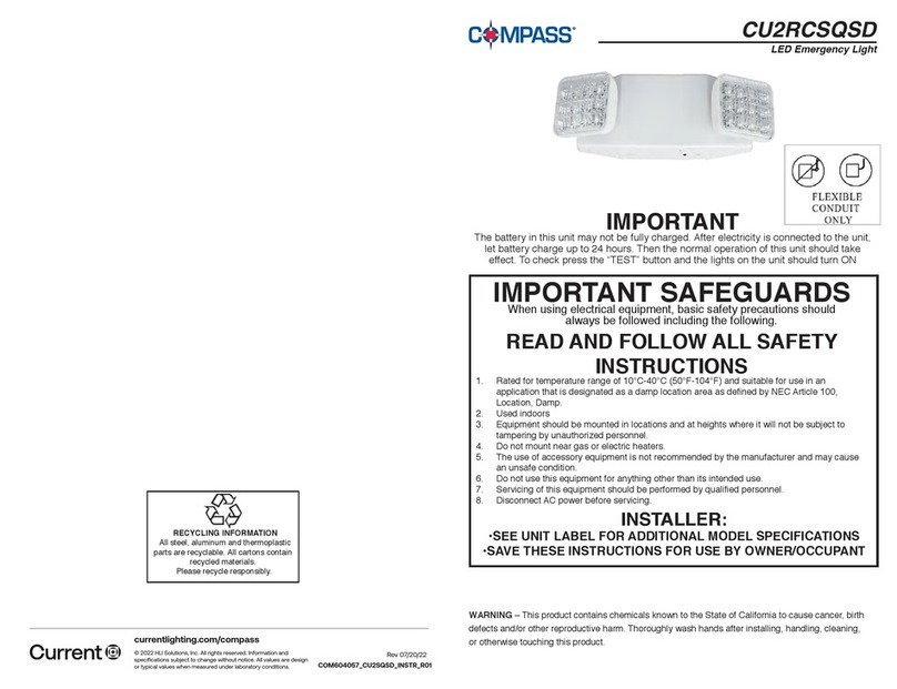
Current Compass CU2RCSQSD quick start guide
