Flying Dog Grape Gym-Star User manual
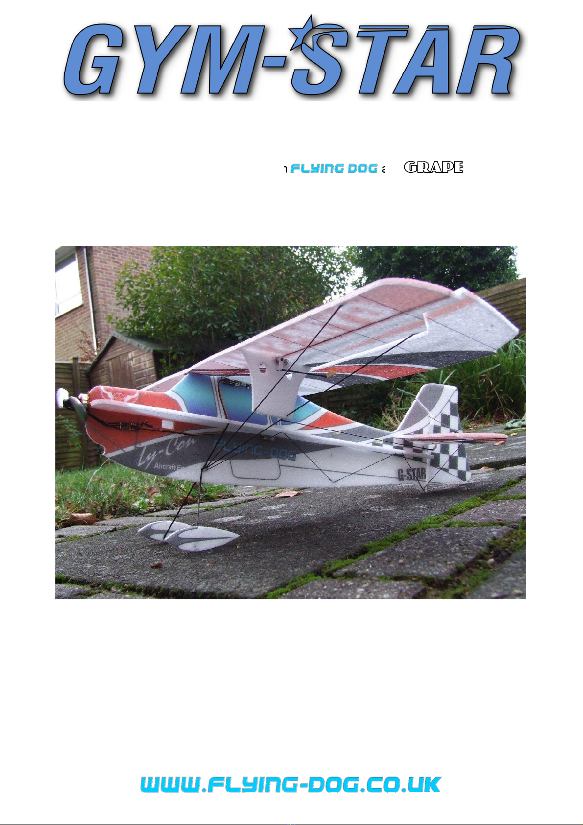
Designed by Andy Whitehead
Thank you for purchasing the Gym-Star from and . The Gym-
Star is intended as both a high-wing trainer and also a 3D model for someone who wants
something a little different from the usual 'Shockflyer' and can perform all the usual 3D
tricks, from hovering (prop-hanging) to knife edge, etc.
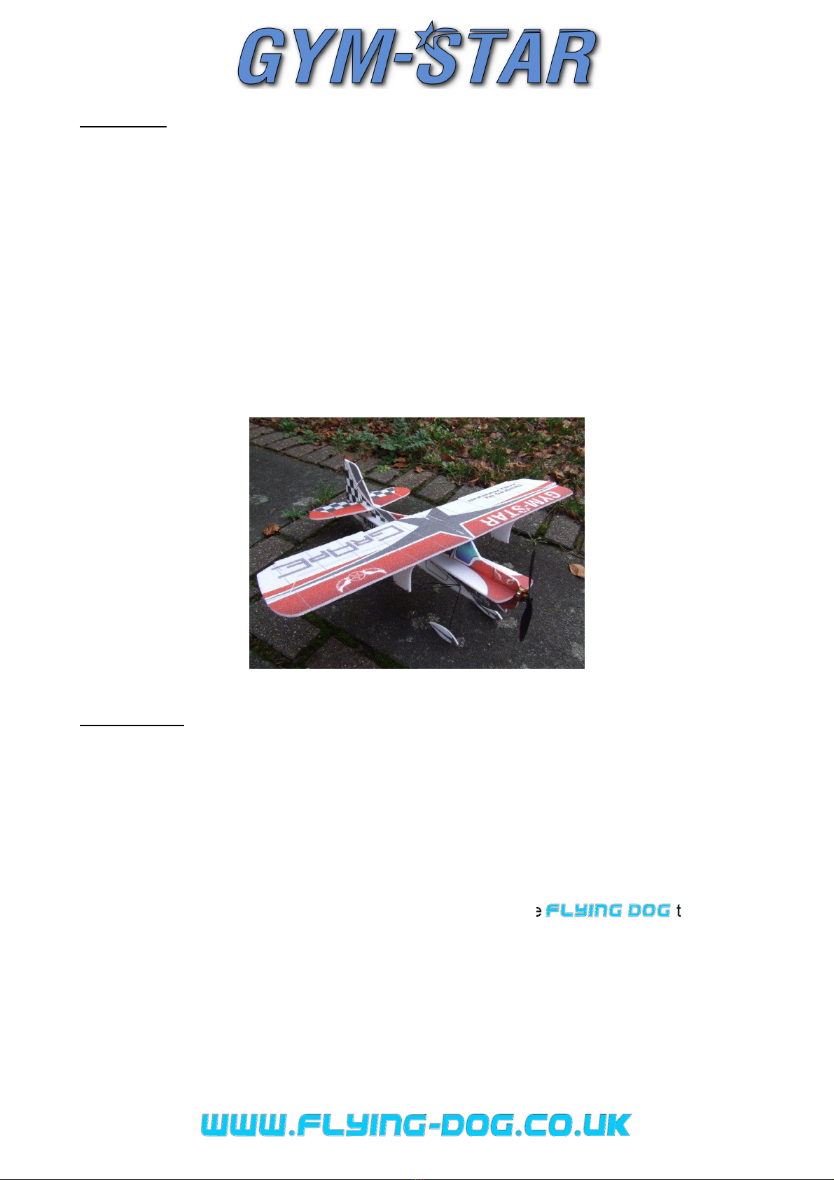
The Gym-Star can be flown both indoors or out in calm conditions, however, if you are
intending on flying mainly indoors, please pay special attention to keeping the weight as
low as possible.
All models fly slower with a lower wing loading, so consider carefully the radio equipment
to be used.
1
Equipment
Many servos and motor/ESC combinations are perfect for this model, but listed below are
some recommendations of gear that the design team have tried and know to work well:
Either:
1 x 9g servo for ailerons – e.g. Hexatronic HXT9 or Inolab HD201HB
Or…
2 x 5g servo for ailerons – e.g. Hexatronic HXT5, Dymond D47 or HiTec HS-35
2 x 5g servos for rudder/elevator – e.g. Hexatronic HXT5, Dymond D47 or HiTec HS-35
1 x 6-10 Amp ESC – e.g. Turnigy Plush 6A, HobbyWing Pentium 10A
1 x 40 Watt+ motor – e.g. A2812-14 (1600kv)
Batteries should be in the 2S 250-350mAh range with a propeller to match the selected
motor (8x4.3 GWS Slow-fly in the case of the suggestion above).
Construction
Anyone who has built an EPP shockie before should find this plane’s construction fairly
normal, however, we always recommend that you read these instructions before
commencing; the designers have built numerous indoor airframes and you may find a few
tricks that aid in constructing straighter, lighter planes.
A few notes on glue... the Gym-Star is constructed mainly from EPP foam which, while
extremely durable, does not bond well with certain types of adhesive. Foam Safe CA and
Epoxy Resins do not work well, so should be avoided.
While normal CA can be used for most of the construction, the team have
extensive knowledge of EPP aircraft and recommend UHU POR for foam to foam joints,
as it produces a flexible bond which resists impacts.
For foam to carbon, or foam to carbon/glass-fibre we have found medium CA to give the
strongest bond.

2
1
.
2
.
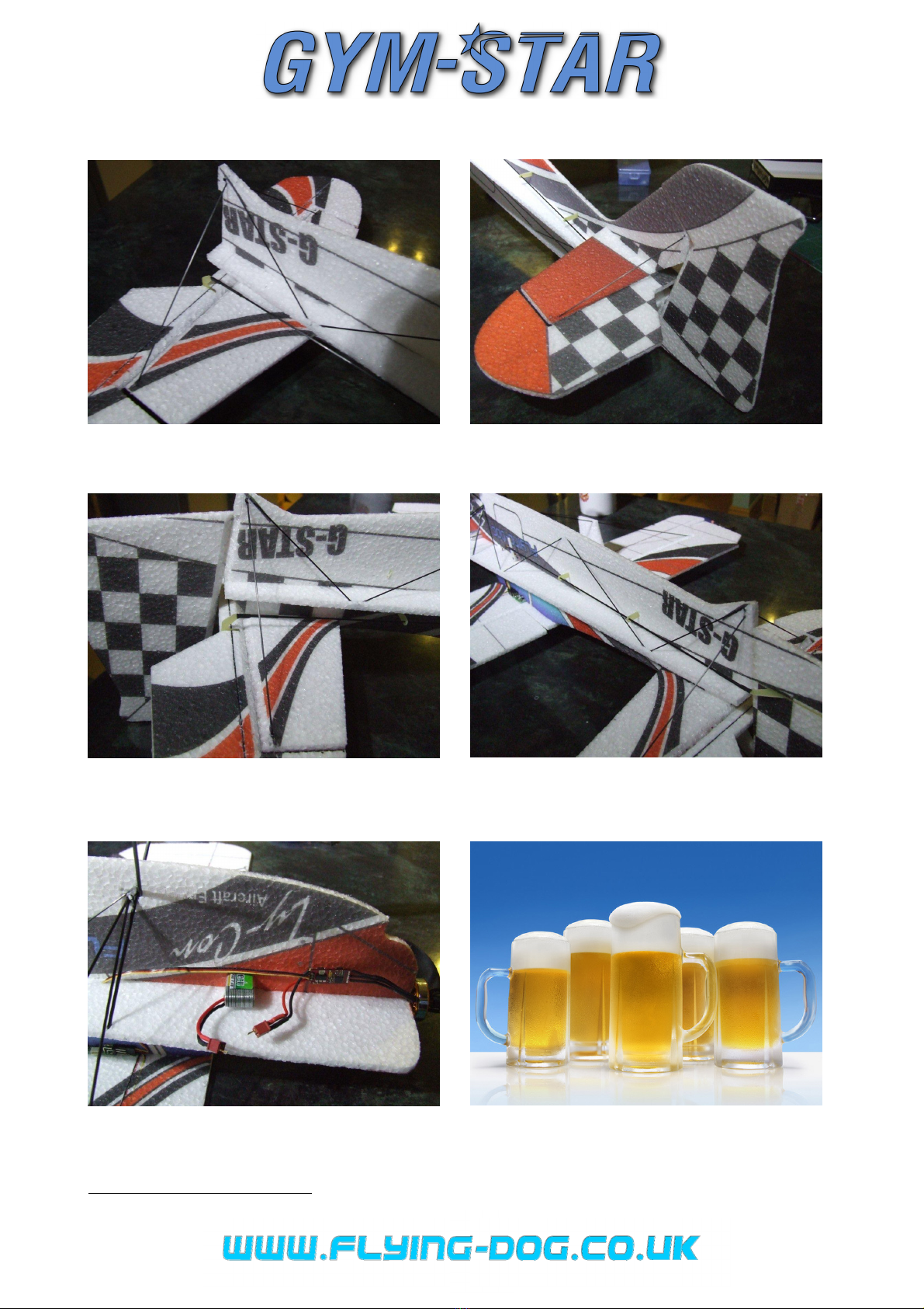
1.
Locate each wing panel and its corresponding
aileron. Apply a small bead of POR to the bevelled
edge of both. Go easy though, as too much glue will
result in a stiff hinge, overloading the aileron’s servo.
2.
Wait 5-10 minutes for the glue to go tacky, then
on a flat surface, press the two together to form a
surprisingly durable hinge. Also join the two halves
of the wing together using POR or CA (our
preference is POR).
3
.
4
.
3.
Locate the 3 x 0.5mm carbon strip and cut it to
760mm long to form the wing spar.
1
With the wing on
a flat surface, push the spar into the slot and fix with
CA. Weight the whole thing down as the glue sets.
2
4.
Glue the spar into the elevator with CA and create
the POR bead hinge, the same as per the wing.
5
.
Using either POR or medium CA, glue the bottom
part of the fuselage (the red printed nose scallop
faces down) to the horizontal piece, checking
everything is square and straight.
3
POR is ideal for this join as it gives working time for
alignment.
5
.
1
The remaining piece is for the elevator, so don't throw it.
2
We've found cold beer works well, as the condensation prevents the CA sticking to the bottle.
3
CD cases make ideal temporary set-squares if you don’t own a proper one.

3
6
.
6.
Cut the 2mm carbon rod into 200mm lengths. Slit
the foam and insert the rods to form the under-cart.
Fix with medium CA.
4
7
a
.
7a.
Cut two pieces of 1mm carbon rod into roughly
130mm lengths and insert into slits cut with a scalpel
starting from the under-cart.
7b
.
Don't fix with glue just yet. Work your way down
the fuselage, inserting carbon stiffeners in the same
configuration as the picture.
When completed, check the whole thing is square
and straight and adjust accordingly. When you are
satisfied it's true, fix each joint with medium CA.
There are various configurations for the aileron
servo/servos on the Gym-Star. Although not
necessarily the most aesthetically pleasing, probably
the easiest way is to simply mount the servo on top
of the wing! If, however, you do want a cleaner look,
it can also be mounted under - though this is a little
more fiddly.
7b
.
The final option is to use two servos for the ailerons,
which then gives you the facility to adjust the
differential and use flap mixes, etc.
The first (on top of the wing) option is pretty straight
forward, so we'll deal primarily with the latter two.
8.
Underwing Servo: Position the servo (spline
forward) onto the upper vertical fuselage and cut
around it so the servo is a tight fit into the foam.
Remove the servo, attach it to the RX and centre it.
With a double horn fitted, CA on the supplied horn.
When the CA is set, the arm can then be secured by
frapping with cotton/thread soaked in CA.
Push the servo back into the fuselage, check the
horn moves freely and attach the wing. Attach a Z
bend to a piece of 2mm rod and with it fitted to the
servo horn, with the pushrod at 90 degrees (see
picture 9) cut it to length, so the end of the rod is
directly over the hinge line.
Repeat for the other side.
8
.
Remove the pushrods and secure the aileron horns
using heat shrink. With the pushrods refitted, mark
and cut slits for the aileron horns.
Do not glue the horns into the ailerons at this stage;
once the wing and bracing have been fitted the horns
can be adjusted in the slits to centre the ailerons
before fixing with CA.
4
Use the dimension provided rather than going by the photo – we’ll let you guess why ☺
150mm
165mm

4
9
.
1
0
.
9
.
Taken from another airframe, this picture shows
the correct orientation of servo horn
5
, push rods,
hinge line and aileron horn.
6
1
0
.
Two Servo option: The RX was placed on the
underside of the wing and the servo wires pushed
into slits, cut with a scalpel, to neaten the whole
installation.
1
1
.
The servos were glued using POR into holes cut
in the under-wing braces. We adjusted the position
of the braces to suit the length of wires on the servo,
but obviously don’t deviate wildly from the photos.
Z-bends were CA glued and heatshrunk to the
carbon push-rods at the servo horn end before being
cut to length so that the carbon lines up with the
hinge line.
Join the pushrod and aileron horn using a short
length of heatshrink as a hinge. With the pushrods
fitted to the servo, mark and cut slits for the aileron
horns, bonding the horns with CA after making sure
the servos are centred.
1
1
.
12.
13.
1
2
.
Attach the upper vertical fuselage to the lower
assembly. Check that it's straight and square.
1
3
.
On a flat surface, weight down the wings and
glue on the fuselage assembly. Check the whole
thing is square and attach the 1.5mm wing braces.
The ends of the braces are pushed into small slits
5
The biased arm should faces forward (like the horns on a bull).
6
The angle between the servo centre, linkage hole and the aileron horn is 90°.
90°
Hinge End of
CF horn
5
before fixing with CA.
14
.
15
.
14
.
Glue on the tailplane, check for alignment, then
attach the 1mm bracing.
15
.
Attach the rudder and upper 1mm bracing.
16
.
17
.
16
.
Elevator/rudder pushrod assembly. Carbon cut
to align with the hinge line and heatshrunk to horn.
Remember to slide the guides on first.
17
.
Equally space each guide, cutting a slit for each in
the foam. Check that the pushrods move freely and
are straight, then fix guides to the fuselage with CA.
18
.
19
.
18
.
Position of the ESC.
7
Battery position adjusts the
Centre of Gravity; as a rough guide for the first flight,
set it about 10mm behind the carbon wing spar.
19
.
Finally sit back with your favourite beverage and
admire your handy work. Your choice of beverage
may vary, but we used the cold bottles from
3
.
7
Radio gear installation can be tidied using POR and small strips of cross-weave tape to fix cabling.

6
Set-up
Dual
-
rates:
•Ailerons 50-100% (±45°max.)
•Rudder 70-100% (±45°max.)
•Elevator 50-100% (±55°max.)
Expo:
•Ailerons 25-50%
•Rudder 10-25%
•Elevator 15-30%
If using 2 servos in the wing, we found 20-25% differential improved the rolls axially.
A flap mix may be set-up with about 55% of down flap mixed to about 35% down elevator.

7
Credits
Designer
Andy Whitehead
Artwork & Manual
Kev Cross
Gaz Holland
Production & Manufacture
Adam Osinski
Marcin Traczyk
Rob Piechulski
Test Pilots
Gaz Holland
Kev Cross
Popular Toy manuals by other brands


Playskool
Playskool Star Wars Yoda with Swamp Stomper 07703 instruction manual

Top Gun Park Flite
Top Gun Park Flite CESSNA EP instruction manual

ROBBE SCHLUTER
ROBBE SCHLUTER Ornith 46 Assembly and operating instructions

VTech Baby
VTech Baby Turtle's Busy Day Soft Book Parents' guide

Costway
Costway TY578067 user manual

Hongda USA
Hongda USA S2006 instruction manual


