Flying Legends P-51D Mustang User manual

The Flying Legends P-51D is a model designed for experienced pilots only. If you are not an experienced pilot that is
comfortable with flying larger high-performance aircraft, do not continue.
These instructions are written with the experienced modeller in mind. They are not intended to be a step-by-step guide, but
highlight a few of the areas of construction to supplement your own modelling experience.
Instruction Manual
Congratulations on your purchase of the
Flying Legends P-51 Mustang!
Wingspan: 99” (2515mm)
Length: 85” (2159mm)
Radio: 6-8 Ch. (8/9 Servos)
Weight: 37 - 39lbs (17 - 18Kgs)
Engine: 75-85cc Petrol Required
Flying Legends P-51 Mustang Specification
FLYING
LEGENDS
241 Green Street,
Enfield,
Middlesex,
EN3 7SJ,
United Kingdom.
Part Number:
Q-FL100

1

2
Introduction
The Flying Legends P-51D Mustang comprises a fully moulded airframe, which has been completely finished at the
factory. Due to this it is vitally important that the components parts are protected during the assembly process to
avoid cosmetic damage to the surface finish. Ensure that your assembly area is of adequate size for a model of this
size and cover your work bench with protective foam to avoid marking of the paint finish.
Ensure that only the highest quality components are fitted to your Mustang, as a high performance scale model
such as this requires matching capability from the engine and radio equipment to ensure safe, enjoyable and
reliable flying. If you have not previously flown a large warbird such as the Mustang we strongly recommend that
an experienced warbird pilot carry out a comprehensive check of the model and then make the initial test flights –
although the Mustang is easy to fly and particularly easy to land, it is a large model with a great deal of inertia, and
this can take a little getting used to for a pilot inexperienced with such large warbirds.
Optional Parts
(Note that some of these parts may already be included depending on the Mustang version selected :
Q-FL100/RE - Retracts with Struts and Air System
Q-FL100/SC - Scale Cockpit
Q-FL100/SP - Alloy Machined Spinner
Q-FL100/MW - Main Wheels/Tyres (Pr)
Q-FL100/RW - Rear Wheel/Tyre
L-IRVSIL/85IL - Silencer In-Line 85cc (DA/BH)
Items Recommended
Engine: 85cc Petrol engine recommended, either DA85 or BH85 are ideal, the prototypes were flown
using a DA85 with a Menz 26 x 10” propeller.
Servos: Ailerons: 2 x 10 Kg.cm min torque req
(Futaba BLS351 used in prototypes)
Elevator: 2 x 10 Kg.cm min torque req
(Futaba BLS351 used in prototypes)
Rudder: 1 x 12 Kg.cm min torque req
(Futaba S9155 used in prototypes)
Flaps: 2 x 15 Kg.cm min torque req
(Futaba S9156 used in prototypes)
Radio Battery: Due to the weight of the Mustang and the flight loads on the servos the current consumption is
much higher than on smaller models - due to this we strongly recommend the use of a battery
pack of at least 3000mAh, ideally of 6.0v to enable the optimum servo response.
Fuel tank: A tank of 950cc was used in the prototypes, this gave plenty of flight time with the DA85 engine
installed.

1
Step 1
Step 2
Step 3
Step 4
Assembly begins with the fitting of your choice of elevator
servo in its pre-fitted mount in the first tailplane half. Note
the orientation of the servo. Use the mounting screws,
grommets and brass ferrules supplied with your servo
and ensure that the lead is drawn out of the tailplane
through the opening in the mount. Temporarily fit a servo
control horn as shown.
Measure the distance from the root face of the tailplane to
the control horn fitted in the previous step.
Transfer this measurement onto a piece of masking
tape on the underside of the tailplane. Develop the
measurement for the thickness of the control horn, then
viewing from the opening in the tailplane, mark the length
of the slot required for free movement of the control horn
over the full range of servo travel.
Using a rotary cutting disc or hand tools, cut a slot wide
enough for clearance on the servo control horn.
Section: Elevator Linkage
As the linkage for each control surface is completed in a similar manner, the elevator linkage is detailed in full here.
A Futaba BLS351 Servo was used on our prototype model.

Step 5
Step 6
Step 7
Step 8
The elevator horn’s position can now be marked out on
the elevator. Use a strip of masking tape to make marking
the elevator easier. Ensure that the slot you mark is offset
slightly outboard when compared to the servo output horn
to allow for the balljoint width and is positioned to ensure
the control horn aligns with the hinge centreline.
Using a small file or rotary cutting disc prepare a suitable
close-fitting slot for the control horn. The slot should be
the full depth of the elevator to the underside of the top
elevator skin, but not through the skin. Take great care not
to cut too deeply and mark the top surface of the elevator.
Roughen the base of the elevator horn with coarse
sandpaper. Glue the horn in place using Hysol or 30
minute epoxy ensuring it is firmly seated in its slot and at
90° to the elevator. Ensure that the horn is vertical - not
leaning to one side - and that the balljoint hole is directly
above the pivot rod of the elevator. Allow glue to fully cure.
Centre the elevator and the elevator servo and make up
the supplied linkage using the 3mm steel elevator pushrod
with an aluminium ball link at the elevator and steel clevis
with a locknut at the servo control horn. Don’t omit the
fitting of a fuel tubing retainer to the clevis.
Repeat all the above steps for the second elevator taking
care to ensure that you work on the underside of the
tailplane.
2

3
Step 9
Step 10
Step 11
Step 12
Prepare your flap servos by fitting their rubber grommets
and ferrules, then screw them to the moulded right-angled
mounting brackets as shown. Note that M3 screws are
used to screw the servos to these brackets. Some servo
ferrules may be too small to accept these screws, so will
have to be changed to a suitable type. Due to the size
of the flaps, we recommend using heavy duty aluminium
servo horns. Make up the flap linkage as shown and
screw to the servo horn.
Remove the flap servo cover and screw the flap servo
in position with the output horn towards the flap. Note
the orientation of the servo’s control horn when the flap
is extended / lowered. When the flap is up / retracted,
the servo should be as far forward as possible without
touching the wing joiner tube.
Using the balljointed end of the flap pushrod as a guide,
mark the flap control horn’s position on the flap. Now
remove the flap from the wing and slot the flap for the
control horn as shown. Note that the slot is towards the
top of the flap.
Temporarily fit the control horn into the slot in the flap and
check for clearance as the flap is lowered and raised.
Roughen the control horn and glue it into the flap using
Hysol or 30 minute epoxy. Refit the flap and adjust the
linkage accordingly. Repeat this procedure for the second
flap. Ensure the horn positions are identical on both flaps.
Section: Aileron/Flap Linkage
A Futaba S9156 Servo was used on our prototype model.

4
Step 13
Step 14
Step 15
Step 16
Prepare your aileron servos by fitting their rubber
grommets and ferrules, then screw them to the moulded
right-angled mounting brackets as you did with the flaps.
Fit a heavy duty nylon control horn. Remove the aileron
servo cover and screw the aileron servo in position with
the output horn towards the leading edge of the wing.
As was done with the elevators, prepare a slot and glue
the aileron control horn into the aileron in line with the
servo output arm using Hysol or 30 minute epoxy. Once
cured, make up your aileron linkage, re-fit the servo cover
and link up the aileron. Test that it moves freely throughout
the entire range of movement. Note that the pre-cut slot in
the servo cover will require enlarging to suit the ouput arm
being used. Repeat for the second aileron.
Note that depending on which version of the P-51D
Mustang you have purchased, some of the following
steps concerning the installation of the retracts and
gear doors will not be applicable as they are factory
installed.
Installing the retracts is a simple task. Simply mount each
unit to the factory fitted plate in the wing using the four
screws supplied for each.
Fit each oleo leg and wheel assembly and tighten the
retaining socket head screw in the retract unit. Ensure
that both legs retract and extend without fouling the wing
and that both wheels track straight ahead.
Section: Retracts
A Futaba BLS351 Servo was used on our prototype model.

5
Step 17
Once you have installed the inner gear doors, fit your air
rams as shown. Ensure that all air lines are fixed to the
airframe to reduce the risk of them being caught by a
retracting undercarriage unit.
Step 18
Step 19
Unless they are factory fitted, the outer doors must be
hinged then attached to the undercarriage leg as shown.
Prepare your rudder servo by fitting its rubber grommets
and ferrules, then screw it to the moulded right-angled
mounting brackets as shown.
Step 20
The retractable tailwheel is steered from the rudder via
an internal closed loop linkage. Begin by removing the
rudder from the fin by withdrawing the hinge pin. Attach
the factory made closed loop cables to the retractable
tailwheel unit as shown. The tailwheel unit can then be
installed in the fuselage. Push it back towards the rudder
to allow the closed loop cables to exit through the rear of
the fuselage.
Section: Rudder
A Futaba S9155 Servo was used on our prototype model.

6
Step 21
Step 22
Step 23
Proceed to the next page for the Full Size Mount Diagram
Connect the closed loop cables to the rudder as shown.
Now the rudder can be re-fitted by installing the hinge
pin and the tailwheel unit can be installed in its mount.
Adjusting the tension of the closed loop is done before
the tailwheel unit is permanently installed, so secure the
tailwheel unit with only a couple of screws to check, then
undo these screws and slide the rudder back to allow the
clevis adaptors to be screwed in or out as required.
Remove the rudder servo cover from the rear of the
fuselage and screw the rudder servo in position and
re-fit the servo cover. Install the prepared pushrod.
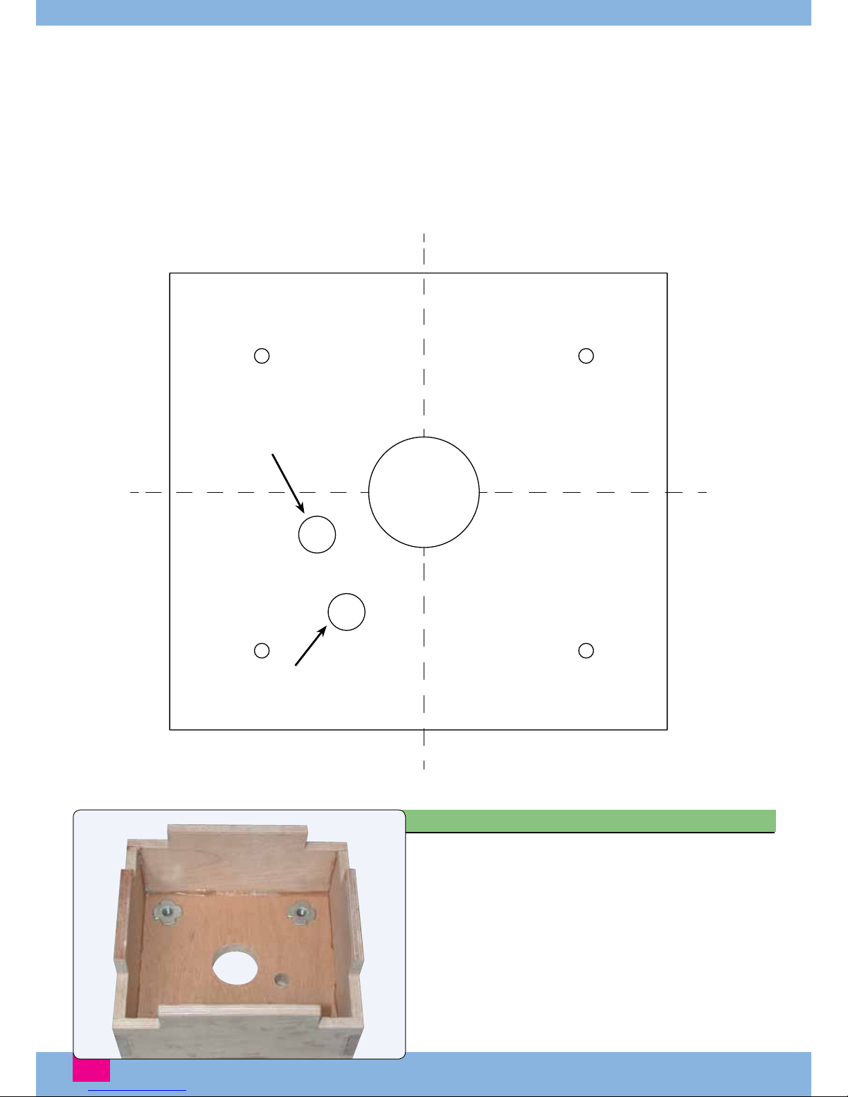
The DA-85 is one of the most commonly available and
suitable petrol engines for the P-51D Mustang. Use the
following template to mark the positions of the holes
required in the factory built engine-mounting box. Other
engines are suitable for this model - simply adjust the
positions of the mounting holes accordingly.
Remove the cowl from the model and test fit the engine
mounting box. Mark the top of the box and remove.
Cut out the engine mounting drill template below and
temporarily paste it to the mounting box as shown.
Section: Engine
7
Step 24
Once the mounting holes have been drilled, remove the
template and fit the supplied captive nuts for your aluminium
engine mounting stand-offs.
Choke Linkage
Throttle Linkage
TOP
DA85 Engine
Mounting Template

8
Step 25
Step 26
Step 27
Step 28
Now screw your engine mounting stand-offs in place.
Offer up the engine mounting box to the fuselage and
mark its position on the firewall. Remove the paint from the
firewall where the mounting box will be glued. Thoroughly
roughen the firewall.
Now glue the mounting box in place using plenty of 1 hour
epoxy or Hysol and leave to cure.
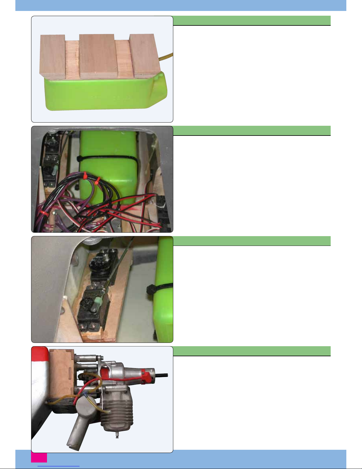
Mounting your throttle and choke servo (if used) will
depend on the engine you are fitting. On our prototypes,
we screwed the throttle and choke servos to a plywood
mount as shown.
9
Step 29
Step 30
Step 31
Step 32
Once you have decided on your choice of fuel tank, you
need to make a simple plywood mount as shown.
The tank is then retained to its mount using two large tie
wraps and double sided tape. Once the fuel tubes have been
connected to the tank and drawn through the bulkhead, the
tank mount can be glued in place in the model’s nose.
Make up suitable linkages for the throttle and choke and
then glue your servo mounting tray in place alongside the
tank in the nose of the model.
The engine can now be installed, the plumbing completed
and the ignition system wired in. Note that the silencer in
these shots is a pre-production prototype.

Step 33
Step 34
Step 35
To complete the air system, remove the rear mounting
plate from the fuselage. Drill the plate for a pair of tie
wraps, then a large volume air cylinder can be fitted to the
top of the plate as shown.
The plate can now be re-installed in the fuselage as
shown. Ensure that the tongues at the rear locate before
tightening the two retaining screws.
To complete the installation, remove the radio plate for
easy access. Mount your receiver, air control valve, retract
servo and any other equipment you require. Re-fit the
plate by locating the tongues then tightening the retaining
screws.
10
Section: Air Supply
Section: Final Installation
9
Section: Final Assembly
Step 38
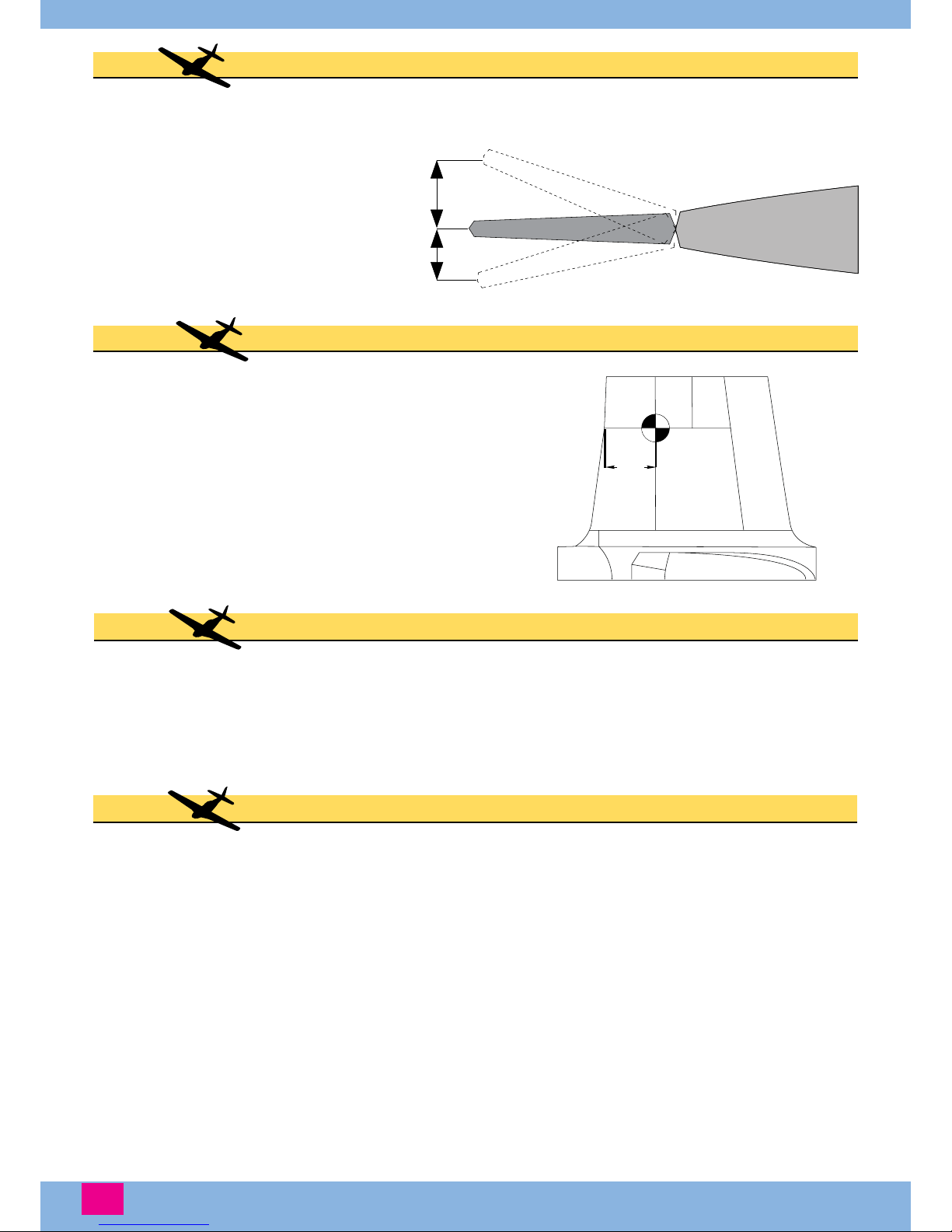
Check the center of gravity to ensure the model
balances correctly 136mm back from the Leading edge
at the crank in the wing. We needed 1.7kg of nose
weight to achieve this on our prototype. Secure any
weight well to avoid it coming loose due to vibration. 136mm
Section: Center of Gravity
Step 37
The wing panels are joined with the large diameter aluminium tube supplied, and the wing is then mounted
to the fuselage using four M4 bolts. The tailplane halves mount to the fuselage using the smaller diameter
aluminium tube supplied and two countersunk M3 screws.
Section: Flying the P-51D Mustang
Step 39
For first flights we recommend the use of a large and open flying site with a good length of runway, not
because the model is hard to fly, but in the event of a minor problem or an engine cut, having plenty of
runway available can make the difference between a safe landing and a wrecked model. If there is going
to be a problem it is most likely to occur during the first few flights, so any extra time required to travel to a
good open site can prove to be well worth the effort.
Do carry out thorough range checks before flying, both with the engine off and running, and check for any
radio interference caused by the engine, throughout the rpm range. Also check all the controls, ensuring
that they operate in the correct direction and with the correct movements, and that there is no slop or lost
motion in any of the linkages and that all clevises and balljoints are secure. Any clevises being used must
have keepers fitted for added security. Finally check the retracts and doors to make sure they are operating
correctly and that no air leaks have developed.
Once happy, refill the fuel and air tanks, and once the engine is running and warmed up check that it will
Check that the controls move in the correct direction and that
their throws correspond to the following when measured at
their widest points.
Ailerons - 25mm up/20mm down
Elevator - 35mm up/30mm down
Rudder - 60mm each way
Flap - 20 Degrees (Take Off)
- 45 Degrees (Landing)
Section: Control Movements
Step 36

10
hold full throttle without sagging. Taxi the model out to the runway being used – although flap can be used
for take off we suggest that this is not done for first flights. Right rudder will be required during the early
stages of the take off run, and some up elevator should be held at first to avoid the model nosing over,
although this must be reduced to nothing as the model accelerates. Once at flying speed a small amount
of up elevator is all that is required to allow the model to lift off, and at full power with an 85cc engine
a comfortable height will quickly be gained, at which point the throttle can be brought back to obtain a
suitable cruise speed.
Fine trimming can now be carried out, and once the model is correctly trimmed we suggest that a few
handling manoeuvres are performed at a safe height, for example turns in both directions, slow flight,
a clean stall, etc, etc. When happy with the handling of the model it is recommended that the model be
slowed down, the undercarriage lowered and flaps applied into landing configuration and a simulated
landing approach is flown at a safe height, so that descent rates and flight attitudes at various throttle setting
can be observed. With this completed the model can be flown through basic and advanced aerobatics until
it is time to land.
The Mustang is a fairly simple model to land, a normal approach should be flown to stabilise the model
and slow it enough to lower the undercarriage, once aligned with the runway the flaps can be lowered in
stages until full flap is applied – note that more throttle will be required due to the increased drag of the
flaps. You will find that the Mustang is very stable in the landing configuration and it should be relatively
simple to position the model for an accurate touchdown, the stability once on the ground being excellent
due to the wide track of the main wheels.
Happy and safe flying!

11
Distributed to all good model shops by
Ripmax Ltd.,
241 Green Street,
Enfield, EN3 7SJ
www.ripmax.com
Ripmax Ltd. guarantees this product to be free from manufacturer’s defects in both material and workmanship at the
date of purchase. This guarantee does not cover faults arising from misuse or accident and the guarantee does not
cover damage or malfunction caused by negligence, misuse, accident, unauthorised repair or modification. In no case
shall Ripmax’s liability exceed the original cost of the purchased kit. In that Ripmax has no control over the final use,
no liability shall be assumed or accepted for any damage resulting from the use of the product by the user. By the
act of using the product, the user accepts all the resulting liability. If the purchaser of this product is not prepared to
accept the liability associated with the use of this product, they are advised to return this product immediately in new
and unused condition to the place of purchase.
The above guarantee in no way affects your statutory rights as a consumer.
Made in China
Table of contents
Popular Toy manuals by other brands


Evolution
Evolution MEGA FUSION instruction manual

Hasbro
Hasbro ForrestFox 6504 Assembly manual

Fisher-Price
Fisher-Price N3193 manual

Fisher-Price
Fisher-Price SCHOOL BUS 77986 instruction sheet

REVELL
REVELL Dassault Rafale M Assembly instructions

Nickelodeon
Nickelodeon Paw Patrol Marshall RC Fire Truck User instruction guide


