FlyingFoam Nurf User manual
Rev 2.0 10/21/13
1
FlyingFoam Nurf
General Assembly Instructions
These instructions apply to the Nurf, an all EPP forward swept flying wing available from
FlyingFoam.com.
Building and operating a remote controlled aircraft involves risk. By building and flying
this kit you are accepting said risks. We assume a basic level of model aviation
knowledge in both building and operating our aircraft. Please seek experienced help
when required. We make every effort to ensure our kits are of the highest quality, and
any documentation is as accurate as we can make it at the time of writing. Due to the
flexible nature of our designs there are many ways to successfully build our kits. We
document what we feel is the best method for general-purpose use. Please refer to
www.flyingfoam.com for further details.
Requirements:
Radio/receiver with elevon mixing
2 mini servos (We like the Hitec 82MG)
Motor: 300+ watt electric power (we like 75 watts per pound of flying weight for
average performance)
Battery: 5000 mAhr 3S lipo or 4350+ mAhr 4s lipo (Nurf has flown with as much
as a 9000mAhr 3S)
Electronic Speed Control: Match to your motor (40+ amps would not hurt)
Prop: 9" for ground clearance (12" max to clear vertical stabilizer, but you might
want a folder or add landing gear for ground clearance)
Options: Folding prop and spinner
Included:
•1.3# EPP fuselage core (cut in half for easy access)
1.9# EPP wing cores (with spar slots)
(6) .188" carbon fiber tube spars
(4) Steel joiners (pre-bent)
(12ft) 5 mil lamination film (to cover the wing and fuse)
(3ft) 1.7 mil lamination film (to cover/hinge the elevons)
(1) 4mm coroplast vertical stab (top/bottom)
(2) 2-56 Threaded rods and nylon clevis
(2) Nylon control horns
(2) 2-56 quick connectors
(2) 1/4" Balsa elevons
(1) 3/32" birch ply firewall
(1) Mylar hatch

Rev 2.0 10/21/13
2
.188 carbon fiber tail pin
3” wide fiberglass tape
(2) Bamboo Skewers
Recommended Tools/Supplies:
Hobby knife with #11 blades
Snap-blade knife
Sanding block with medium grit (120-150) paper
5 minute epoxy
CA –Medium and Thick
Fiber-reinforced packing tape
Masking tape
Covering iron
Rotary tool with small router bits
Flat building surface
1/2” brass tube
Assembly Instructions
NOTE: We strongly recommend building the wing first as this will allow you to test fit
the wing on the uncompleted fuselage in order to place your gear for best CG position.
Wing Core Preparation
1. Start by separating the wing cores from the beds. SAVE THE BEDS - They will be used
throughout
Note: It is normal for the beds to stick to the cores, so be careful when separating.
2. Lightly sand the cores to remove imperfections. A sanding block with 120 grit
sandpaper works well for this.
3. Use a knife to remove any flashing or excess EPP from the beds. It is important the
cores lay flat in the beds, as it will help ensure building a straight wing.
4. Vacuum or use compressed air to remove all dust and remaining debris.
Join The Wing Cores
5. Tape the bottom beds together with a strip of masking tape. Repeat for the top beds.
6. Glue the wing halves to the center wing section with 5-minute epoxy. Align the wing
in the bottom beds and use tape to hold the joints. Apply weights to hold flat, or hold
with your hands if you are not doing anything for the next 5 minutes. When the epoxy
sets, remove the weights and masking tape.

Rev 2.0 10/21/13
3
Spar Installation
7. The carbon fiber spars are joined at the wing panel joints with the pre-bent joiner
wires that are found in the small parts bag. The spars will also be wrapped at the joint
with ~1.5” of the 3” wide fiberglass tape. Start by dry fitting the joiners and spars; de-
burr the ends of the joiners/spars with sandpaper if required. Test fit the spars in the
wing cores and adjust the joiners and spar slots as required. Once the dry fit is
satisfactory use epoxy to join the carbon fiber spars with the bent wire spar joiner and
wrap the spars at the joints with the fiberglass tape.
8. The spars can be glued into the EPP cores with CA glue, epoxy or 3M Spray contact
adhesive. To use 3M glue, spray a medium coat of 3M into the spar slot of the cores
and let dry for 5 to 10 minutes. Spray a light coat of 3M on 1 side of the glued together
spar assembly and IMMEDIATELY place the spar in the spar slot in the wing core. DO
NOT WAIT. The wet 3M glue will allow you to position the spar in the slot. IF YOU WAIT
TOO LONG YOU WILL NOT BE ABLE TO MOVE IT!!
9. Weight the spars and wing so they remain flat in the beds while the glue dries.
NOTE: Moving the wing before the glue fully dries may allow the spars to slide in the
foam and result in a twisted/warped wing.
10. Repeat the process for the bottom spars.
Servo Installation
10. After installation of the bottom spars you should have the wing cores in the top beds
with the bottom of the wing facing up.
11. Locate the pockets for your servos (we recommend metal gear servos with the
mounting ears removed). Measure 17” out along the elevon hinge line from the wing
panel joint formed by the center and outer wing panels. From that mark measure
forward and perpendicular from the elevon hinge line to just behind the location of the

Rev 2.0 10/21/13
4
spar. This will be the outboard edge of your servo pocket. You can now mark the
outlines of your servo using this mark as a guide. Make sure you keep the servo pocket
behind the spar so you do not cut into it while creating the pocket. Your servo pockets
should be a snug fit in the foam to ensure you minimize any excess play. Perform the
same procedure for the other side of the wing.
12. To complete the wire run for the servo leads use a sharp blade and straightedge to
cut a slit for the wire that extends from the servo pocket to the centerline of the wing.
You may need servo extensions to complete the wire run. There should be a few inches
of wire lead extending from the centerline to make it easier to plug in the servos.
13. Once you are satisfied with the dry fit of your servos you should plug them in in
order to center and install the proper control horns. You can then glue the servos into
the pockets. We recommend “Goop” type glue to secure the servos, but CA or double-
sided tape will work. We also recommend using fiber-reinforced tape to cover the
servo. Don’t forget that you need to prime EPP with 3M 77 any time you expect tape to
stick. Don’t worry about cutting a slot in the tape for the servo control horn yet as we
will also be covering the wing with lamination film. Make sure the servo wire is inserted
in the wire run.
Final Wing Preparation
14. You can round/shape the forward wing tips to your liking. We use an old CD-ROM
as a template, but any object with a similar radius will work. Use a sharp blade and your
preferred template to round the tips. Once rounded you can use a sanding block to
sand the tip profiles to a compound curve.

Rev 2.0 10/21/13
5
NOTE: Do not use too much pressure with the sanding block or you risk tearing instead
of sanding.
15. Perform a final sanding of the entire wing with a sanding block and 120-150 grit
sand paper. This sanding will help remove the thin layer of heat-affected EPP from the
hotwire process, which will help the lamination film better adhere to the surface of the
foam.
16. Now is also the best time to sand and bevel your balsa elevons in order to reduce
dust/debris on the bench during covering.
Wing Covering
17. Once you are satisfied with the wing’s finish it is time again to vacuum the wing,
elevons and beds to make sure they are free of any debris. Also make sure the bench is
free of any dirt/debris, as the laminating film likes to attract anything you miss.
18. Using one of the wing beds as a template, cut out four pieces of 5 mil lamination
film. Make sure to cut the pieces long enough to overlap in the center of the wing.
19. With the wing facing bottom-up in the top beds position a piece of the laminating
film over half the wing. There should be a few inches of overlap in the center. Use a
medium-hi covering iron and start in the center of the panel and work out to the tip.
Then work from the center of the panel to the center of the wing. Repeat for other side.
NOTE: 5 mil lamination film will not stretch as much as some iron-on coverings. It does
not wrinkle as easily, but if you start a wrinkle it is harder to iron out. Keep the covering
tight with your free hand and avoid too much slack as you iron down the covering.
Practicing with a small scrap of film on the foam beds is recommended. When the film
goes clear under the heated covering iron you have reached the right temperature.
20. Once the bottom of the wing is covered you can place the wing in the bottom beds
with the wing facing up and repeat the same process for the upper surface.
NOTE: For best performance it is critical you do not impart a twist/warp in the wing
while covering. Keep the wing flat in the beds as much as possible while covering; take
your time; and attempt to use the same technique and heat for all four panels.
Elevon Installation
21. Once the wing is covered you can cover and install the elevons. The elevons can be
covered with the provided 1.7mil lamination film or your preferred tape. Whichever
method you prefer, it is important that the elevons are flat after covering.
22. You can use either tape or lamination film for the hinge. We prefer the 1.7mil
lamination film, but a tape such as 3M Blenderm will work.

Rev 2.0 10/21/13
6
23. Once the elevons are hinged you can cut out access holes for the servo control
arms; plug in the servos; and allow the arms to center.
24. The control rods should run perpendicular to the hinge line. Use a fine tip marker to
mark the holes for the horns and a small drill bit to make the holes for the screws. Once
the holes are marked and drilled you can install the horns.
25. With the wing flat in the top beds and the bottom of the wing facing up you can use
a straight edge to ensure the bottom of the wing airfoil towards the trailing edge and
the bottom of the elevon are flush. This should help set proper reflex for your maiden
flight. You can now measure and bend the 2-56 control rods for the elevons.
26. There are EZ Links in the small parts bag that will allow you to bend a 90 degree
angle in the control rod and attach to the servo control horn.
Fuselage Prep
27. Now that the wing is complete you can tape the fuselage halves together with the
rudder in place to prepare for test fit of components and CG testing.
NOTE: We recommend using regular masking tape for the following steps as blue or
“painters” masking tape does not stick well to EPP.
28. Once the fuselage is taped together you can mark the CG range on both sides of the
fuselage. The recommended CG range is from the leading edge of the wing saddle to
3/8” behind the leading edge. Use a straight edge and a fine tip marker to mark this
range on the bottom edge of the fuselage on both sides.
29. Place the wing in the saddle and then tape your motor, ESC and any other gear you
plan to fly onboard in their approximate locations.
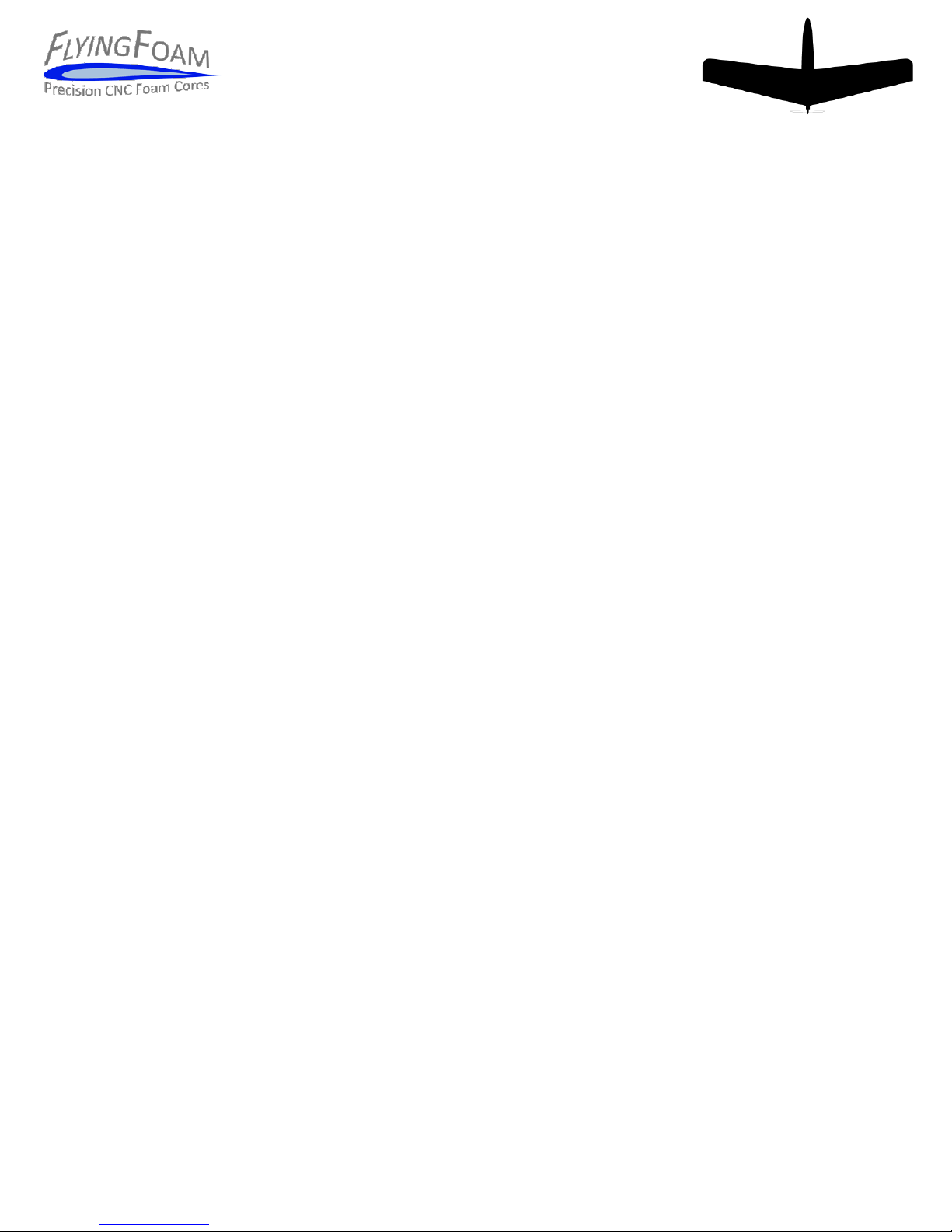
30.Using the tail pin as a balance bar, position the fuselage so that your forward CG
marks are centered over the pin.
Rev 2.0 10/21/13
7
31. You can now position your battery and reposition other components until the Nurf
balances on your pin.
32. Once you are happy with the balance of the Nurf you can mark the locations of the
components for reference during pocketing. You can now remove the tape and
components and begin the pocketing process.
NOTE: See flyingfoam.com for preferred pocketing schemes for various Nurf
configurations.
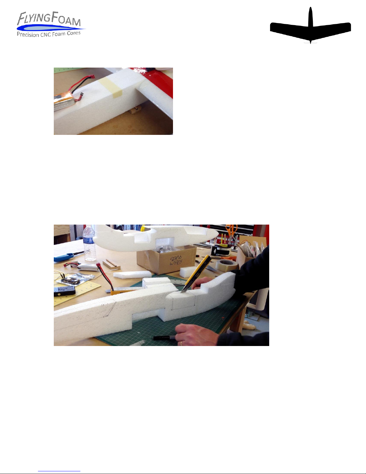
33. We recommend a snap blade knife and/or a rotary tool with small router bit to
complete the pocketing process.
34: Once you are happy with the fuselage pockets you can glue the two fuselage halves
together with 3M 77 or a light coat of 5-minute epoxy. DO NOT glue the vertical fin in
yet. It will be glued in place after the fuselage is covered.
NOTE: If using 3M 77 to join the two fuselage halves together make sure you protect the
pockets AND tail area from overspray.

Rev 2.0 10/21/13
8
Final Fuselage Prep
35. You can now use your sanding block with 120-150 grit to round the edges of the
fuselage and lightly sand the surface.
36. Once sanding is complete it is time again to vacuum the cores and your bench to
prepare for covering of the fuse.
37. The last step before covering the fuse is to make sure you have added your favorite
fiber-reinforced tape to areas of high stress. We recommend reinforcing the wing
saddle at leading edge, the firewall, and any place where the foam gets thin around the
pockets. Don’t forget to prime with 3M 77 and to protect from overspray.
Fuselage Covering
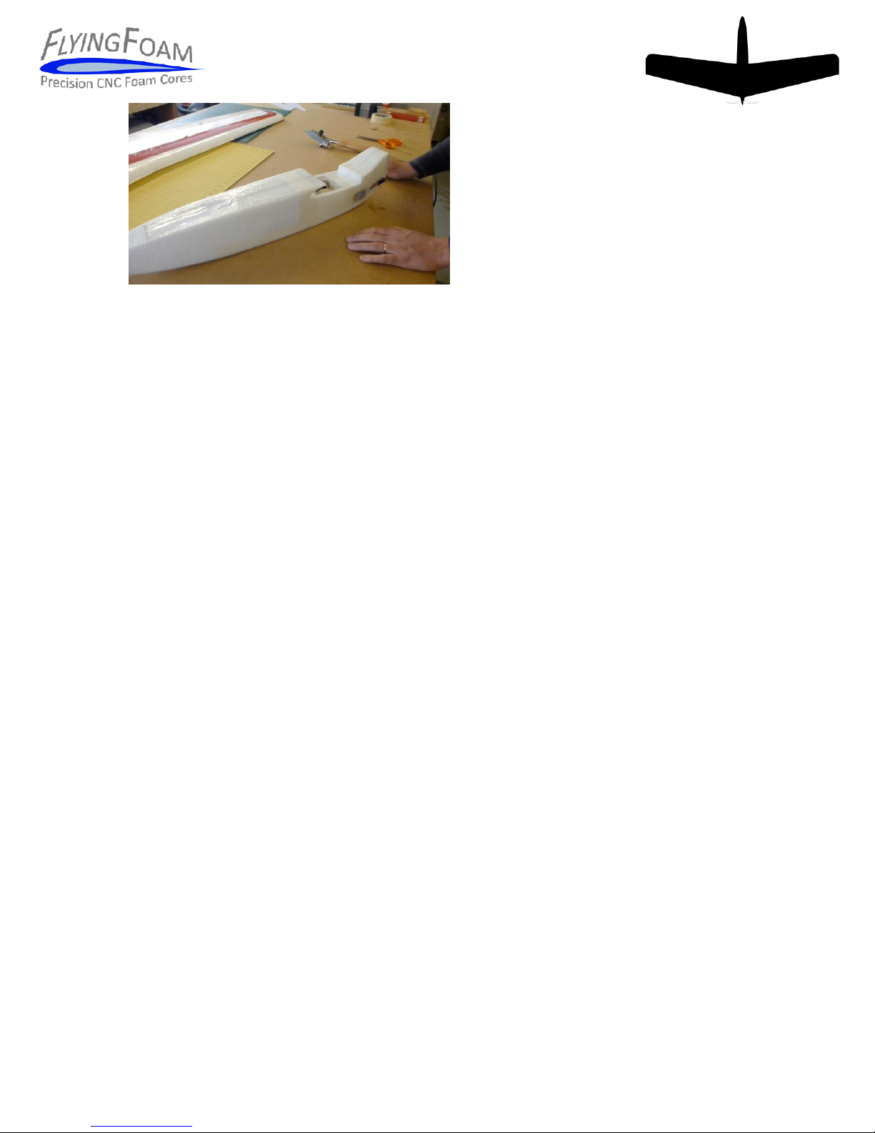
38. Using the fuselage as a template, cut four pieces of lamination film with enough
length to overlap the firewall.
39. Starting with the bottom of the fuselage, position the film so there is enough to
overlap the firewall. Using your covering iron carefully apply the film to the bottom of
the fuselage.
NOTE: We recommend temporarily placing the tail in the tail slot while covering to help
maintain correct dimensions of the fuselage.
40. Once the film is applied you can use scissors or a sharp knife to trim the film along
the edges. We recommend leaving just enough film to easily roll around the corners
with the covering iron.
41. Repeat this process for both sides and the top of the fuselage. Once the fuselage is
covered you can use a sharp knife to cut the covering as required for access to your
pockets and tail fin slots.
Rev 2.0 10/21/13
9
Tail Fin Installation
42. Temporarily place the wing in the saddle with the top and bottom fin in position.
Once you are happy with the fit of the both the bottom and top fin, mark the bottom fin
with a pencil along the fuselage outline. Remove the bottom fin and scuff the bottom
fin inside these lines. This will help the epoxy achieve a better bond.
43. Glue the bottom fin in place with 5-minute epoxy. Be careful not to glue the two
fins together as the top fin is designed to be removed.
NOTE: As the top fin is used to hold the wing in position it is important that you achieve
a snug fit between the upper wing surface and the bottom surface of the top tail. You
may need to carefully trim the corroplast to achieve best fit.
44. When the glue on the bottom tail is dry you can install the tail pin. The fuselage is
already pre-cut for the pin. Make sure the wing and tails are properly inserted and mark
the end of the tail pin with a black marker. While the marker is still wet you can push
the pin into the hole to transfer the mark to the top fin.
45. Remove the top fin and there should be a mark transferred from the pin. Use this
mark as a guide and drill a hole through the top fin with a 3/16 drill bit.
46. Insert the bamboo skewers into corrugations near the leading and trailing edge of
the fin. The goal is to add stiffness to the tail. Trim to fit.
NOTE: We recommend using light fiberglass, CA hinges or other thin material to glue
doublers on either side of the top fin where the tail pin hole is located. This will help
keep the hole from becoming enlarged over time.

Rev 2.0 10/21/13
10
Final Assembly
46. Lamination film will hold plastic compatible paint very well. You can also use trim
tape and/or colored packing tape to add color to the design.
NOTE: To maintain visual line of site and proper orientation it is highly recommended to
use a very high contrast color scheme.
47. Install your motor, speed control and receiver per the manufacturer’s instructions.
For your maiden flight we recommend replacing any expensive cameras or similar
equipment with ballast; once the plane is properly tested and trimmed you can replace
the ballast with your real equipment and have fun.
48. Plug in the ailerons and install the wing and check for proper travel and direction.
Low
High
Aileron
1/4 - 3/8
1/2 –3/4
Elevator
1/4 - 3/8
1/2 - 3/4
49. To check the center of gravity you can use a tube or rod (a pencil works) under the
fuse as a balance bar, or the tips of your fingers just behind the leading edge of the wing
where it meets the fuse.
NOTE: Since the Nurf is a flying wing it has a fairly tight CG range and it is much easier
to maiden with the CG at the leading edge of the wing. You can slowly move the CG
back as you get comfortable with the plane.
Maiden Flight
NOTE: It’s beyond the scope of these assembly instructions to teach you how to fly.
Please adhere to AMA safety regulations, use common sense and have fun.
50. During the maiden flight we recommend that the plane be trimmed so that you can
fly straight and level at half throttle from one side of the field to the other without pilot
corrections.

Rev 2.0 10/21/13
11
NOTE. The Nurf has 4 degrees of thrust line built into the motor mount and we have
found it works well with several different motors and payload configurations. However,
to get best performance it is good to check your configuration. Even if you plan to fly
with an IMU our other auto stabilization method there is no substitute for a well-
balanced and trimmed aircraft.
51. Once you have the aircraft properly trimmed for cruise you can check your thrust
angle by flying straight and level at a comfortable cruise speed and slowly move the
throttle setting to full throttle. There should be very little movement of the nose if the
thrust line is correct. If you see large pitch changes during this test then land and check
your CG. If your CG is correct then you may need to add washers to the motor mount to
adjust thrust line: If the Nurf is pitching nose-up when throttle is applied then add
washers behind the bottom two bolts of your X-mount. If it is pitching nose-down then
add washers behind the top two bolts of your X-mount. We recommend one washer on
each bolt be added to the stack until the thrust line is correct. Perform flight tests as
described above and repeat until you are happy with the results.
Care and Feeding
Make sure you pre-flight the aircraft before every flight. The Nurf was designed to take
abuse, but you can still break it. The good news is it’s also easy to repair. During our
testing we found the wing tends to outlast the fuselage by a wide margin. In particular,
we have found that lamination film is very strong, but once it fails it likes to run. So
check for signs of cracks in the covering as well as the foam. We recommend repairs
with “Goop” or epoxy followed by fiber-reinforced tape.
Don’t forget the Nurf was designed to be hacked. We love feedback –especially
pictures/videos of your creations. We will maintain notes on tips and tricks, as well as a
gallery of images and videos at flyingfoam.com.
Enjoy! Team FlyingFoam.
Building and operating a remote controlled aircraft involves risk. By building and flying
this kit you are accepting said risks. We assume a basic level of model aviation
knowledge in both building and operating our aircraft. Please seek experienced help
when required. We make every effort to ensure our kits are of the highest quality, and
any documentation is as accurate as we can make it at the time of writing. Due to the
flexible nature of our designs there are many ways to successfully build our kits. We
document what we feel is the best method for general-purpose use. Please refer to
www.flyingfoam.com for further details.
Popular Aircraft manuals by other brands


Nova
Nova SECTOR manual

Ocean Rodeo
Ocean Rodeo Stick-Shift manual

Airglas
Airglas GLH3000 Nose Ski Instructions for Continued Airworthiness

Piper
Piper TOMAHAWK Pilot's operating handbook and faa approved airplane flight manual

Jabiru
Jabiru J170-C Pilot operating handbook

Hyperflight
Hyperflight X-res instruction manual


