3
A
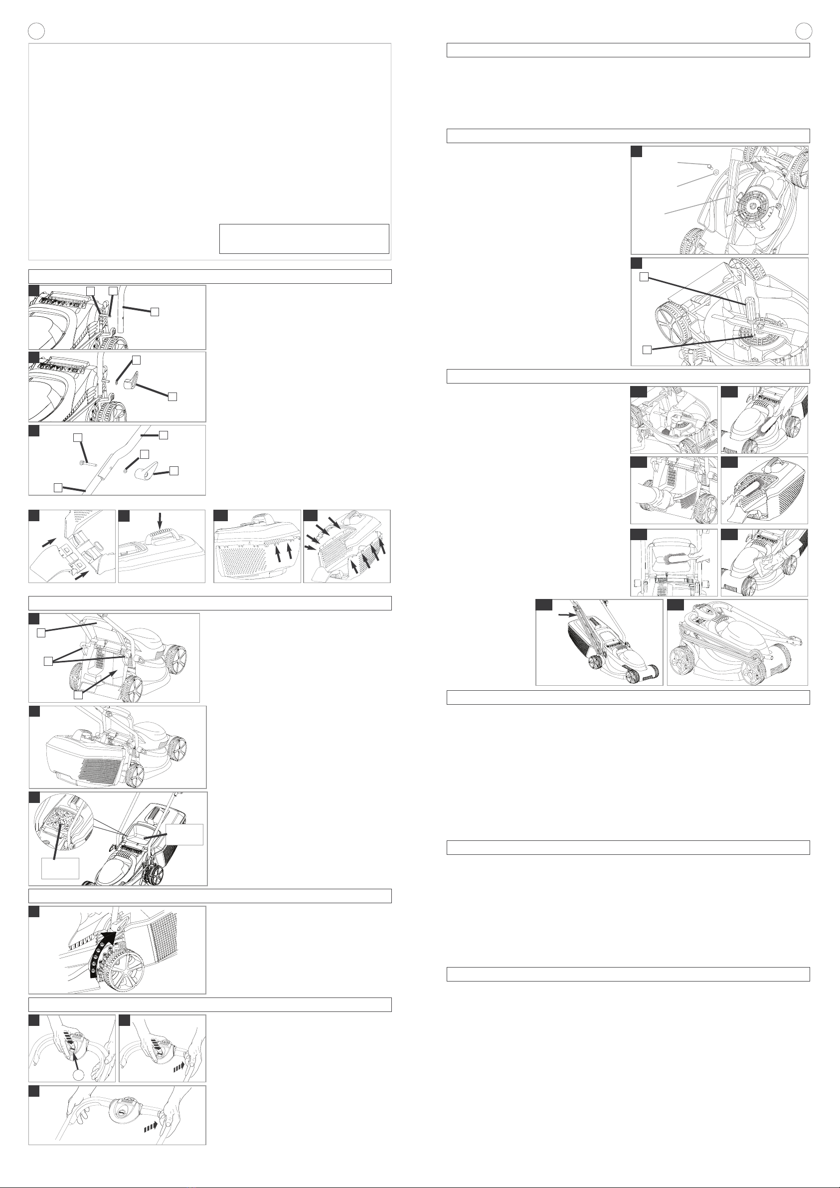
•The Loose Parts Pack is packa ed underneath the deck.
Assembly of Lower Handles to Deck
1. Place the bolt (A2) throu h the hole in the lower handle
(A1) until the lower handle fits into the recess (A3)
2. Place the washer (B1) and the win knob (B2) on to
the bolt and ti hten the win knob. It may take 20 - 25
turns to fully ti hten on initial assembly.
3. Repeat on the other side.
Assembly of Upper Handles to Lower Handles.
1. Ensure the upper handle is located correctly with the
lock-off button on the switchbox uppermost.
2. Ensure the upper handle (C1) and the lower handle
(C2) are ali ned correctly.
4. Fit the bolts (C3), washers (C4) and win knobs (C5).
Ti hten the win knob.
5. Fit the cable to the handles with the clips provided.
Make sure the cable is not trapped between the upper
and lower handles.
Grassbox Assembly
1. Slide the rassbox ton ue into the slots in the
rassbox lower until it clicks securely into position (D)
2. Push the rassbox handle into the slots in the
rassbox upper until it clicks securely into position. (E)
3. Startin at the rear of the rassbox, locate the
rassbox upper into the rassbox lower by ali nin the
clips (F1). Ensure all clips are correctly located.(F2)
before clickin into position.
4. Clip the two halves to ether, ensurin all clips are
securely connected.
Assembly Instructions
B
4
Cuttin Hei ht Adjustment
Removin and Fittin the Blade
C
Grassbox
D
Switch off, wait until the blade has stopped rotatin and
disconnect from the mains electricity supply BEFORE at-
temptin to remove or refit the blade.
Always handle the blade with care - sharp ed es could
cause injury. USE GLOVES.
Removin the Blade
1. To remove the blade bolt, hold the blade firmly with a
loved hand and with a spanner, loosen the blade bolt
by turnin it anti-clockwise (O).
2. Remove the blade bolt, washer and blade.(O)
3. Inspect for dama e and clean as necessary.
4. In the event of a blade becomin difficult to remove, in-
sert a screwdriver (P1) into the hole (P2) to lock the
drive, then use a spanner (13mm A/F) to loosen the
blade bolt by turnin the spanner anti-clockwise. En-
sure the screwdriver is removed before atemptin to
turn on the machine.
Renew your metal blade after 50 hours mowin or 2 years
whichever is the sooner - re ardless of condition. If the
blade is cracked or dama ed replace it with a new one.
Fittin the Blade
1. Fit the blade to the shaft with the sharp ed es of the
blade pointin away from the shaft and you are able to
read the text on the blade ‘This side to rass’
2. Re-assemble blade bolt throu h the washer and the
blade.
3. Hold the blade firmly with a loved hand and ti hten the
blade bolt firmly with a spanner . Do not over ti hten.
O
blade
blade bolt
washer
J
N
Startin and Stoppin
To Start your Lawnmower
1. Connect plu to mains and switch on.
The switchbox is provided with a lock-off button (L1) to
prevent accidental startin .
1. Press and hold the lock-off button (L) on the
switchbox, then squeeze one of the Start/Stop levers
towards the upper handle (M).
2. Continue to squeeze the start/stop lever towards the
upper handle and release the lock-off button (N).
3. Lower the lawnmower to its proper operatin position
and commence mowin .
•NOTE - There are two start/stop levers fitted. Either
one can be used for startin the lawnmower.
• IMPORTANT - Do not use the start/stop levers
intermittently
To Stop your Lawnmower
1. Release the pressure on the Start/Stop lever.
L M
1
Fittin Fully Assembled Grassbox to Lawnmower.
1. Lift safety flap (G1)
2. Make sure the dischar e chute is clean and free from
debris (G2)
3. Locate fully assembled rassbox onto 2 location
points (G3) at the rear of the deck as illustrated in
pic. H
4. Locate safety flap onto the top of the rassbox. En-
sure the rassbox is securely located.
•IMPORTANT !
AFTER FITTING ENSURE NO GAP REMAINS BE-
TWEEN THE SAFETY FLAP AND THE GRASSBOX.
•Removal is the reverse procedure.
• For lar er areas of rass where rass collection is
not required you can use your lawnmower without
the rassbox. Ensure the Safety Flap is fully closed.
The desi n of the safety flap permits the cut rass to
be dischar ed downward behind the machine.
Grassbox Full Window
• As the rassbox fills up, rass will be visible throu h
the window (J).
• When the window/ rassbox is full it is time to empty
the rassbox.
rassbox
empty
rassbox
full
P
1
EF1 F2
2
3
1
2
1
2
3
4
5
G
1
2
3
H
1
2
Cuttin Hei ht Adjustment
• Hei ht of cut is adjusted by raisin or lowerin the
wheels usin the hei ht adjustment lever (K)
• There are five hei hts of cut on this product. (20 -
60 mm)
• NOTE
A medium hei ht of cut is recommended for most
lawns.
The quality of your lawn will suffer and collection will
be poor if you cut too low.
K
If any part is found to be defective due to faulty manufacture
within the uarantee period, Husqvarna UK Ltd., throu h its
Authorised Service Repairers will effect the repair or
replacement to the customer free of char e providin :
(a) The fault is reported directly to the Authorised Repairer.
(b) Proof of purchase is provided.
(c) The fault is not caused by misuse, ne lect or faulty
adjustment by the user.
(d) The failure has not occurred throu h fair wear and tear.
(e) The machine has not been serviced or repaired,
taken apart or tampered with by any person not
authorised by Husqvarna UK Ltd.
(f) The machine has not been used for hire.
( ) The machine is owned by the ori inal purchaser.
(h) The machine has not been used commercially.
* This uarantee is additional to, and in no way
diminishes the customers statutory ri hts.
Failures due to the followin are not covered, therefore it
is important that you read the instructions contained in
this Operator's Manual and understand how to operate
and maintain your machine:
Failures not covered by uarantee
* Replacin worn or dama ed blades.
* Failures as a result of not reportin an initial fault.
* Failures as a result of sudden impact.
* Failures as a result of not usin the product in
accordance with the instructions and recommendations
contained in this Operator's Manual.
* Machines used for hire are not covered by this uarantee.
* The followin items listed are considered as wearin
parts and their life is dependent on re ular
maintenance and are, therefore not normally subject
to a valid warranty claim: Blades, Electric Mains cable
*Caution!
Husqvarna UK Ltd. does not accept liability under the
warranty for defects caused in whole or part, directly
or indirectly by the fittin of replacement parts or
additional parts that are not either manufactured or
approved by Husqvarna UK Ltd., or by the machine
havin been modified in any way.
Guarantee & Guarantee Policy
Service Recommendations
1. We stron ly recommend that your product is serviced
at least every twelve months, more often in a
professional application.
2. Always use enuine Spare Parts.
3. Prepacked spares are available from most Husqvarna
UK Ltd. stockists.
4. Your product is uniquely identified by a silver and
black product ratin label
5. If you have a problem with your machine contact your
local Approved Service Centre ensurin you have full
details of your product as described on the product
ratin label.
6. Should it be necessary for work to be carried out by
your Service Centre, it is important to take your
complete machine includin cable and any extension
cables used.
A network of specialist dealers can be found in your local
Yellow Pa es.
To obtain service on your product simply telephone or
visit your local Service Centre.
Should you require service under the terms of our uarantee
the Service Centre will require proof of purchase.
All of the centres listed stock enuine Spare Parts.
NOTE: Our Service Repairers act on their own behalf
and are not empowered to commit or le ally bind
Husqvarna UK Ltd. in any manner whatsoever.
Fault Findin Hints
Fails to Operate
1. Is the correct Startin procedure bein followed? See
‘To Start your Lawnmower’
2. Is the Power Turned On?
3. Check the fuse in the plu , if blown replace.
4. Fuse continues to blow?
Immediately disconnect from the mains electricity supply
and consult your local approved Service Centre.
Poor Grass Collection
1. Disconnect from the mains electricity supply.
2. Clean the outside of the air intakes, the dischar e
chute and the underside of the deck.
3. Raise to a hi her hei ht of cut. See Cuttin Hei ht
Adjustment.
4. If poor collection persists.
Immediately disconnect from the mains electricity supply
and consult your local approved Service Centre.
Excessive Vibration
1. Disconnect from the mains electricity supply.
2. Check that the blade is fitted correctly?
3. If the blade is dama ed or worn, replace it with a new one.
4. If vibration persists?
Immediately disconnect from the mains electricity supply
and consult your local approved Service Centre.
Lawnmower becomes heavy to push
1. Disconnect from the mains electricity supply.
2. In lon rass or uneven round, the hei ht of cut
should be raised to a hi her position. See Cuttin
Hei ht Adjustment.
3. Check that the wheels and rollers can rotate freely.
4. If problem persists?
Immediately disconnect from the mains electricity supply
and consult your local approved Service Centre.
Carin for your Lawnmower
Cleanin
• USE GLOVES
• IMPORTANT:- It is very important that you keep your lawn-
mower clean. Grass clippin s left in any of the air intakes or
under the deck could become a potential fire hazard.
1. Remove rass from under the deck with brush. (R1)
2. Usin a soft brush - remove rass clippin s from all air
intakes (R2), the dischar e chute (R3) and the rass
box (R4).
3. Usin a soft brush, remove rass clippin s from the vi-
sion window (R5).
4. Wipe over the surface of your lawnmower with a dry
cloth (R6).
•IMPORTANT:- Never use water for cleanin your lawn-
mower. Do not clean with chemicals, includin petrol, or
solvents - some can destroy critical plastic parts.
Storin your Cable
• Your electric cable can be wrapped around the cable
wrap win knobs to enable tidy and safe stora e (S1).
Storin your Lawnmower:
• Loosen the win knobs to enable the handles to be
folded over the product (S2).
• Store in a dry place where your lawnmower is pro-
tected from dama e
At the End of the Mowin Season
1. Replace blade, bolts, nuts or screws, if necessary.
2. Clean your lawnmower thorou hly.
3. Make sure that the electric cable is stored correctly to
prevent dama e.
R1 R2
R3 R4
R5 R6
S2S1
How to Mow
1. Start mowin the ed e of the lawn nearest to the power point so the cable is laid out on the lawn you have already
cut.
2. Mow twice a week durin the rowin season, your lawn will suffer if more than a third of its len th is cut at one time
and this may also result in poor collection.
Do Not Overload Your Mower
Mowin lon thick rass may cause the motor speed to drop, you will hear a chan e in the motor sound. If the motor
speed drops you may overload your lawnmower which may cause dama e. When mowin in lon thick rass a first
cut with the cuttin hei ht set hi her will help reduce the load. See Cuttin Hei ht Adjustment.
CABLES - IMPORTANT
If you want to use an extension cable when operatin your
product, only the followin cable dimensions should be used.
- 1.0 mm2: max len th 40 m
- 1.5 mm2: max len th 60 m
- 2.5 mm2: max len th 100 m
Minimum ratin :
1.00mm2 size cable, 10 amps 250 volts AC.
•YOUR PRODUCT IS SUPPLIED WITH CABLE WIRED
DIRECTLY INTO THE PRODUCT.
1. If the supply cord is dama ed, it must be replaced by
your local Husqvarna UK Ltd. Approved Service Centre
or similarly qualified persons in order to avoid a hazard.
2. Flymo Extension Cables are available from your local
Husqvarna UK Ltd. Approved Service Centre.
3. Do not wire an extension cable directly to your product
yourself. Please contact your local Husqvarna UK Ltd.
Approved Service Centre for further information on the
connectors and kits available.
4. Only use extension cables specifically desi ned for
outdoor use and which conform to one of the followin
specifications: Ordinary rubber (60245 IEC 53), Ordinary
PVC (60227 IEC 53) or Ordinary PCP (60245 IEC 57)
CONNECTORS - IMPORTANT
• Flymo connectors are suitable for use with 2 core cable
only. Under no circumstances should these connectors
be used for earthed products.
• All Flymo connectors and cables are of splashproof
construction. They are not waterproof and must not be
left outside permanently nor should they be submer ed
or immersed in water. Do not let cable lay or trail throu h
pools of water or splashed with water from hose pipes.
MAINS PLUG REPLACEMENT - IMPORTANT
• If the plu supplied is cut off it should be destroyed.
There is an electric shock hazard if a cut off plu is
inserted into a 13 amp socket.
1. No earth required. Flymo products are double insulated
to EN60335 and under no circumstances should an
earth be connected to any part of the product.
2. Ensure the mains volta e suits your product
3. IMPORTANT!
The wires in the mains lead are coloured in accordance
with the followin code:
BLUE - NEUTRAL
BROWN - LIVE
The wire which is coloured BLUE must be connected to
the Terminal which is marked with the letter 'N' or
coloured BLACK.
The wire which is coloured BROWN must be connected to the
Terminal which is marked with the letter 'L' or coloured RED.
4. It is important that the outer sheath is clamped correctly
into the 3-pin plu .
5. If in doubt consult your local Service Repairer or
qualified electrician before the machine is used.
6. A 13 Amp fuse must be fitted to the Mains Plu .
7. The normal plu fuse and household fuse only protect
the electrical equipment and are not a safe uard
a ainst electrocution.
If your product is hard wired i.e. non-detachable mains
electric cable, a conversion kit and extension cable is
available from all Approved Service Centres which can
be found in your local Yellow Pa es.


