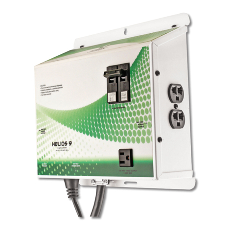
P2410W P2420W
10A
12V/24V
Auto(GEL/SEL/FLD)
Default: GEL
5mA/12V 3mA/24V
12V System<22V 24V System<55V
10A 20A
170W/12V;340W/24V 340W/12V;680W/24V
-35℃~+45℃
IP68
0.16kg
5V*n
10s
≤3000m
82*58*20mm
GEL
14.2V*n
13.8V*n
13.2V*n
12.6V*n
11.1V*n
-3Mv/2V/℃
4. Use Suggestions
3.Please keep the battery and the controller in the same environment as far as possible.
Because the external temperature sensor will monitors the environment of the controller then
compensates the temperature of the battery. It will also protects the controller from over-
temperature.
6.It is unwise to leave any battery empty for long time and any battery should be charged at
least once a month. If it is not charged for a long time, it is likely to cause permanent
damage to the battery. So we have certain requirements for our users during use, please
keep charge greater than discharge so that the battery can be fully charged.
1.The controller automatically recognizes the system voltage 12V/24V when it is powered up.
Please connect the DC load first and then the battery that ensure the reliability of the
connection.
2.As this device might get heat while charging, so please try to install it in a ventilated and
heat-dissipating environment.
4.Please choose the wire that is the same as or larger than the required size of the device.
Also the length of the wires should not be too long to avoid misjudging the voltage of the
device due to the wires’ loss.
5.Please ground the positive terminal if grounding is required. This device is a common
positive design.
5. Status LED Indications
LED Indications
PV
Battery
Load
Status
Off
Steady On
Slow Flash
Quick Flash
Off
Steady On
Slow Flash
Quick Flash
Steady On
Flashing
Solar input not charging / Unconnected
/ PV Reversed
PV voltage higher than the controller light
control voltage
Charging Mode
Solar Over Voltage
Battery Disconnected
Battery On
Battery Over Discharged
Battery Over Voltage
DC Load On
DC Load Overload
Functions
6. Controller Specifications
Model NO.
Max Load Output Current
Battery System Voltage
No-load Loss
Max Solar Input Voltage
Rated Solar Charge Current
Max Solar Input Power
Operating Temperature
IP Protection
Net Weight
Light Control Voltage
Light Control Delay Time
Operating Altitude
Controller Dimension
Battery Voltage Battery Parameters
Battery Types
Boost Charge Voltage
Float Charge Voltage
Boost Charge Recovery Voltage
Over-discharge Recovery Voltage
Over-discharge Voltage
Auto Temperature Compensation
Package Instruction
Manual
Bluetooth
PARAMETERS
Packaging Status
YES
Optional
ITEMS
Note: In the absence of special instructions, the parameters in the data sheet shall prevail. If
you have the requirements for other battery type for setting or require Bluetooth function,
please make a remark when ordering. And we also support thecustomization of special wires.
Load Mode Always on (Load mode can be customized )
