Magnetrol Solitel User manual

Installation and Operating Manual
Solitel
Vibrating
Rod Level
Switch

Read this Manual Befo e Installing
This manual provid s information on th Solit l®
Vibrating Rod L v l Switch. It is important that all
instructions ar r ad car fully and follow d in s qu nc .
D tail d instructions ar includ d in th Complete
Installation s ction of this manual.
Conventions Used in this Manual
C rtain conv ntions ar us d in this manual to conv y
sp cific typ s of information. G n ral t chnical mat rial,
support data, and saf ty information ar pr s nt d in
narrativ form. Th following styl s ar us d for not s,
cautions, and warnings.
Notes
Not s contain information that augm nts or clarifi s
an op rating st p. Not s do not normally contain
actions. Th y follow th proc dural st ps to which
th y r f r.
Cautions
Cautions al rt th t chnician to sp cial conditions that
could injur p rsonn l, damag quipm nt, or r duc
a compon nt’s m chanical int grity. Cautions ar also
us d to al rt th t chnician to unsaf practic s or th
n d for sp cial prot ctiv quipm nt or sp cific
mat rials. In this manual, a caution box indicat s a
pot ntially hazardous situation which, if not avoid d,
may r sult in minor or mod rat injury.
Wa nings
Warnings id ntify pot ntially dang rous situations or
s rious hazards. In this manual, a warning indicat s an
immin ntly hazardous situation which, if not avoid d,
could r sult in s rious injury or d ath.
Safety Messages
Th Solit l syst m is rat d by th IEC for us in Cat gory
II, Pollution D gr 2 installations. Follow all standard
industry proc dur s for s rvicing l ctrical and comput r
quipm nt wh n working with or around high voltag .
Always shut off th pow r supply b for touching any
compon nts. Although high voltag is not pr s nt in this
syst m, it may b pr s nt in oth r syst ms.
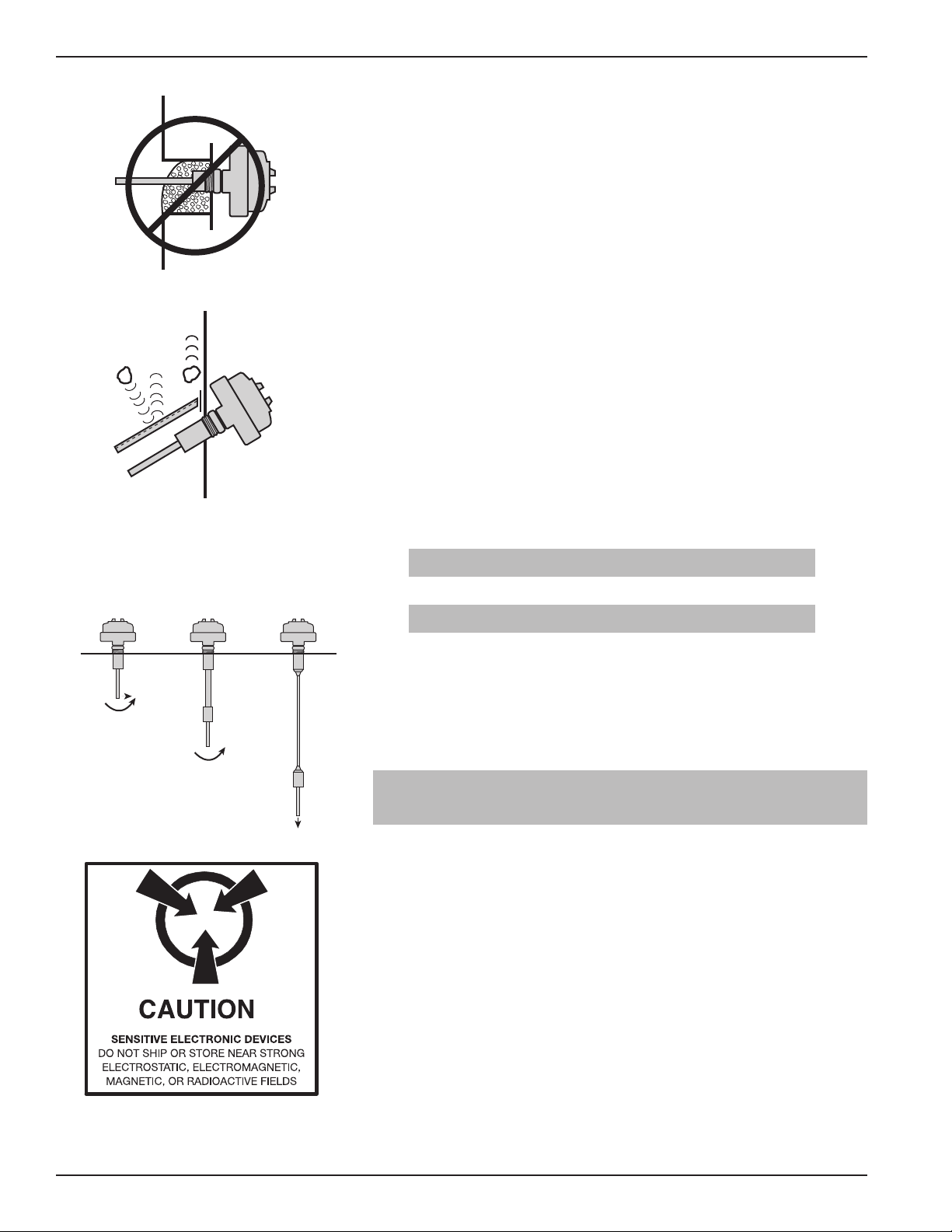
El ctrical compon nts ar s nsitiv to l ctrostatic
discharg . To pr v nt quipm nt damag , obs rv saf ty
proc dur s wh n working with l ctrostatic s nsitiv
compon nts.
This d vic compli s with Part 15 of th FCC rul s.
Op ration is subj ct to th following two conditions: (1)
This d vic may not caus harmful int rf r nc , and (2)
This d vic must acc pt any int rf r nc r c iv d, includ-
ing int rf r nc that may caus und sirabl op ration.
Low Voltage Di ective
For us in Cat gory II installations. If quipm nt is us d
in a mann r not sp cifi d by manufactur r, prot ction
provid d by quipm nt may b impair d.
WARNING! Explosion hazard. Do not conn ct or
disconn ct quipm nt unl ss pow r has b n switch d off
or th ar a is known to b non-hazardous.
Notice of Copy ight and Limitations
Copyright © 2019 Magn trol Int rnational
MAGNETROL r s rv s th right to mak chang s to th
product d scrib d in this manual at any tim without
notic . MAGNETROL mak s no warranty with r sp ct
to th accuracy of th information in this manual.
Wa anty
All MAGNETROL l ctronic l v l and flow controls ar
warrant d fr of d f cts in mat rials or workmanship
for ight n months from th dat of original factory
shipm nt.
If r turn d within th warranty p riod; and, upon
factory insp ction of th control, th caus of th
claim is d t rmin d to b cov r d und r th warranty;
th n, MAGNETROL will r pair or r plac th control at
no cost to th purchas r (or own r) oth r than
transportation.
MAGNETROL shall not b liabl for misapplication,
labor claims, dir ct or cons qu ntial damag or xp ns
arising from th installation or us of quipm nt. Th r
ar no oth r warranti s xpr ss d or impli d, xc pt
sp cial writt n warranti s cov ring som MAGNETROL
products.
Quality Assu ance
Th quality assuranc syst m in plac at MAGNETROL
guarant s th high st l v l of quality throughout th
company. MAGNETROL is committ d to providing
full custom r satisfaction both in quality products and
quality s rvic .
Th MAGNETROL quality assuranc syst m is
r gist r d to ISO 9001 affirming its commitm nt to
known int rnational quality standards providing th
strong st assuranc of product/s rvic quality availabl .

1.0 Introduction
Th Solit l®Vibrating Rod L v l Switch provid s r liabl
l v l d t ction of bulk solids and powd rs. This compact,
int gral switch is suitabl for high or low l v l d t ction
in hopp rs and silos. It may also b us d for plugg d
chut d t ction.
Th rugg d, singl -pi c prob is suitabl for us in a
vari ty of powd rs or granular mat rials with a minimum
bulk d nsity of l ss than on pound p r cubic foot.
1.1 Principle of Operation
Th Solit l®rod vibrat s at a 350 Hz fr qu ncy. Wh n
m dia mak s contact with th rod, th vibration is damp-
n d. Th att nuation of th vibration is d t ct d by th
int gral mount l ctronics, changing th status of th r lay.
2.0 Installation
2.1 Unpacking
Unpack th instrum nt car fully. Mak sur all compo-
n nts hav b n r mov d from th packing mat rial.
Insp ct all compon nts for damag , and r port any
conc al d damag to th carri r within 24 hours.
Ch ck th cont nts of th carton, making sur it agr s
with th packing slip and th purchas ord r. V rify that
th mod l numb r imprint d on th nam plat match s
th numb r on th packing slip and th purchas ord r.
R port any discr panci s to th factory. Ch ck and r cord
th s rial numb r for futur r f r nc wh n ord ring parts.
Serial Number
2.2 Mounting
Prior to installation, it is r comm nd d that th unit b
calibrat d using a sampl of th m dia to b m asur d.
Refe to Calib ation, Section 2.5.
IMPORTANT: Handl th instrum nt with gr at car ,
sp cially th prob . Any impact on th prob can damag
th vibration syst m.
3
56-601 Solitel Vibrating Rod Level Switch
Figure 1

Th SOLITEL switch is mount d to th v ss l using a
11⁄2" NPT thr ad d conn ction.
• Ensur that th tip of th prob is locat d at th d sir d
switching point giving consid ration to th slop angl of
th mat rial.
• Th switch may b install d v rtically or horizontally
(at a downward angl ) as shown in Figur 1 on pag 3.
• Avoid mounting th s nsor in a r c ss wh r buildup
could damp n th vibration. S Figur 2.
• Do not cut or b nd th vibrating rod.
IMPORTANT: A d fl ction plat is r quir d wh n th
prob is xpos d to falling mat rial, collaps d arch, or, in th
cas of a low l v l switch, wh n th drag forc of th mpty-
ing mat rial xc d th sp cifications. Th d fl ctor can b
a baffl plat or angl iron (11⁄2" ×11⁄2" ×1⁄8") locat d 4 to
6 inch s abov th rod. S Figur 3.
Obs rv th sp cifications for b nding forc (F),
torqu (M), and pull forc (F) as indicat d b low:
S Figur 4.
Standard: F = 100 pounds (445 N)
M = 63 foot pounds (85 Nm)
Ext nd d Rigid: M = 63 foot pounds (85 Nm)
Wh n using an xt nd d l ngth v rsion for low l v l
alarm, mount th prob abov th outl t of th v ss l to
avoid th prob b ing dragg d along by th outflowing
mat rial.
2.3 Electrostatic Discharge (ESD)
Handling Procedure
MAGNETROL l ctronic instrum nts ar manufactur d
to th high st quality standards. Th s instrum nts utiliz
l ctronic compon nts which may b damag d by static
l ctricity pr s nt in most work nvironm nts. Th
following st ps ar r comm nd d to r duc th risk of
compon nt failur du to l ctrostatic discharg :
1. Ship and stor circuit boards in anti-static bags. If an
anti-static bag is not availabl , wrap board in aluminum
foil. Do not plac boards on foam packing mat rials.
456-601 Solitel Vibrating Rod Level Switch
Figure 2
Figure 3
VXH VXR VXK
F
M
F
M
Figure 4

2. Use a grounding wrist strap when installing and
removing circuit boards. A grounded workstation is
also recommended.
3. Handle printed circuit boards only by the edges. Do not
touch components or connector pins.
4. Ensure that all electrical connections are completely made
and none are partial or floating. Ground all equipment to
a good earth ground wiring.
2.4 Wiring
Manually position the housing in the correct direction to
allow for easy wiring. The housing can rotate one full turn.
1. Make sure the power supply is turned off.
2. Unscrew and remove housing cover.
3. Connect power leads to the proper terminals. To simplify
wiring, the terminal strips may be removed from the
module by lifting the front edge of the terminal block.
Refer to Figure 5.
a. 120 VAC – Connect the “hot” wire to terminal marked
L1 and the “neutral” to terminal L2/N. There is no con-
nection to the center terminal.
b. 24 VDC – Connect wires to terminals (+) and (-). There
is no connection to the center terminal.
4. To ensure optimum noise immunity, attach the ground
wire to the green grounding screw inside the housing base.
Caution: On 4 VDC units, the negative terminal of the power
supply is isolated from ground and proper earth grounding
of the power supply shield wire is necessary for noise
immunity.
5. Connect relay terminals. Refer to Figure 6.
6. Set the fail-safe umper as described in the table on page 6.
For alarm applications, it is recommended that the
de-energized status of the relay be used as the alarm status.
This allows detection of power failure as an alarm status.
7. Wiring is complete. Replace the housing cover.
8. Apply power to the unit.
5
56-601 Solitel Vibrating Rod Level Switch
Figure 6
L1(+) No Connection L2/N(-)
Power
LED
Fail safe jumper
Sensitivity
adjustment
NO CO NC
Relay
Figure 5

2.5 Calibration
Ensur that th fail-saf jump r is install d in th prop r
position as d scrib d in Tabl 1. Th LED will show
r d wh n in alarm condition and gr n wh n in normal
condition. T st th op ration of th switch by holding,
and th n r l asing th vibrating rod; th LED will
chang color.
Th s nsitivity of th switch can b chang d using th
d nsity adjustm nt scr w. Not that this adjustm nt scr w
has 270 d gr s of rotation. Do not rotat past th stops.
NOTE: If the adjustment is too sensitive, the switch may detect
even slight residue of material rather than level.
Prior to installation, it is r comm nd d that th unit b
calibrat d using a sampl of th m dia to b m asur d.
656-601 Solitel Vibrating Rod Level Switch
Power Material Level Fail-Safe Jumper LED Color Relay Coil Relay Terminal
NO to CO NC to CO
6–7 7–8
On High A position Green De-energized Open Closed
B position Red Energized Closed Open
On Low A position Red Energized Closed Open
B position Green De-energized Open Closed
Fail High/Low A/B De-energized Open Closed

3.0 Reference Information
3.1 Troubleshooting
SOLITEL is a simpl and r liabl d vic . How v r, car
must b tak n to avoid impacting or damaging th vibrat-
ing prob .
In th v nt th SOLITEL stops vibrating, th following
proc dur will id ntify if th probl m is with th l ctron-
ic modul or with th s nsor:
Disconn ct th wir s going to th s nsor. (T rminals 3, 4,
and 5). Th following giv s th xp ct d voltag rang
b tw n th s nsors.
If th s voltag r adings ar not obtain d, th l ctronics
ar d f ctiv and n d to b r plac d. If th s voltag s ar
m asur d, th probl m is with th s nsor.
NOTE: The probe and electronics must be matched to ensure
proper operation. Use the following procedure to match
the electronics and the vibrating probe:
1. Conn ct th wir s from th s nsor to t rminals 3, 4, 5.
Th r will b two wir s of th sam color and on wir of
diff r nt color. Th two similar wir s go to t rminals 4 and
5; th singl wir go s to t rminal 3.
2. If th pot ntiom t r is lab l d “d nsity” turn to th low
position – if lab l d “s nsitivity” turn to th high position.
Not this pot ntiom t r has a 270 d gr turn.
3. Apply pow r to th l ctronic modul .
4. Turn th l ctronic modul ov r.
7
56-601 Solitel Vibrating Rod Level Switch
Terminals Voltage
3 and 4 4 to 6 VDC
3 and 5 0.3 to 1.0 VAC
Figure 7
Front Rear

5. Connect a digital multimeter between points MP5 on the
back of the module and ground connection terminal 3 on
the electronic module) or the body of the vibrating probe.
See Figure 7 on page 7.
6. Adjust potentiometer P2 on the rear of the electronic mod-
ule to obtain a voltage between 0.4 volts and 1.0 volts. The
reading should be as close to 1.0 volt as possible.
7. Grasp the vibrating section of the sensor with your hand.
The vibration should stop and the relay will change state.
8. Remove your hand from the sensor. The relay will
change state.
9. The electronic module and probe are now matched.
3.2 Agency Approvals
3.2.1 CSA
Model Approval
VXX-D1BX-XXX Class I, D v. 2
Groups A, B, C, & D
Class II, D v. 1
Groups E, F, & G
Type 4X
3.3 Replacement Parts
Item Description Part Number
1 Base 004-9189-001
2 Cover 004-9105-001
3 Cover o-r ng 012-2101-345
4 Electron cs module:
110 VAC Z30-9011-001
24 VDC Z30-9011-004
5 Bracket 005-6680-001
6 Probe o-r ng 012-2408-001
7 Snap r ng 010-5138-001
8 Sleeve 004-0111-001
9 Probe Consult Factory
856-601 Sol tel V brat ng Rod Level Sw tch
These un ts have been tested to EN 50081-2
and EN 50082-2 and are n compl ance w th
the EMC D rect ve 89/336/EEC.
These un ts have been evaluated to the
appl cable UL and CSA standards. CSA s
accred ted as a NRTL (Nat onal Recogn zed
Test ng Laboratory) n the Un ted States.
NRTL/C
➁
➀
➂
➃
➄
➅
➆
➇
➈

3.4 Specifications
3.4.1 Performance
Description Specification
Input voltage 110 VAC +10/-15%
24 VDC (±10%)
Powe consumption L ss than or qual to 3 VA
Ope ation f equency 350 Hz
Output elay SPDT 8 amp @ 250 VAC
SPDT 1 amp @ 24 VDC
Time delay 6–10 s conds
(d p nding on d nsity adjustm nt)
P ocess connection 11⁄2" NPT
Housing NEMA 4X
Ope ating p ocess conditions
Standa d -4 to +230 °F
(-20 to +110 °C)
Enhanced pe fo mance -40 to +320 °F
(-40 C to +160 °C)
Ambient elect onics temp. -40 to +140 °F, s chart at l ft
(-40 to +60 °C)
Relative humidity 98%
Maximum p ocess p essu e 360 psig
Minimum Density 50 oz/ft3or 0.05 gm/cm3
Mate ials specifications
Vib ating od 316 stainl ss st l
Rigid extension 316 stainl ss st l
Inse tion length
VXH 8.25 inch s (209 mm)
VXR 10 to 100 inch s (25 to 254 cm)
Maximum mechanical load on p obe
St anded p obe 63 Ft/lbs. (85 Nm)
Extended igid p obe 63 Ft/lbs. (85 Nm)
56-601 Solitel Vibrating Rod Level Switch
-40 F
(-40 C)
00
-40 F
(-40 C)
140 F
(60 C)
95 F
(35 C)
167 F
(75 C)
320 F
(160 C)
Process Temp.
Ambient Temp.

10 56-601 Solitel Vibrating Rod Level Switch
Standard Length
DIMENSIONAL SPECIFICATIONS inches (mm)
1.73 (44) Dia.
6.34
(161)
Insertion
length
8.25
(209)
3.44 (87)
Rotation clearance
11/2" NPT
process connection
3/4" NPT
Conduit connection
2.75
(69)
4.63
(117) Dia.
3.63
(92)
3/4" NPT
plugged
1.5
(38)
3.4.2 Physical
Extended Rigid Probe
1.73
(44) Dia
6.34
(161)
Insertion
length
11/2" NPT
process connection
3.44 (87)
Rotation
clearance
3/4" NPT
Conduit
connection
2.75 (69)
4.63
(117) Dia.
3.63
(92)
1.5
(38)
3/4" NPT
plugged

11
56-601 Solitel Vibrating Rod Level Switch
3.5 Model Numbers
3.5.1 Solitel®Level Switch Standard and Extended Rigid Probe
VD1B
1 Standard, length in inches
2 Enhanced performance*, length in inches
H Standard rigid, 8.25" (21 cm) length
R Extended rigid
0 110 VAC
2 24 VDC
DESIGN TYPE
PROBE TYPE
INPUT VOLTAGE
Design type code 1 or 2 with probe type code R: Code 000
fixed length of 8.25" (21 cm)
Design type code 1 or 2 with probe type code R
10 to 100 inches Example: 10 inches = code 010
INSERTION LENGTH
*Recommended for temperatures up to +320° F (+160° C) or for sticky materials.

Service Policy
Ow ers of Mag etrol co trols may request the retur of
a co trol or a y part of a co trol for complete rebuildi g
or replaceme t. They will be rebuilt or replaced prompt-
ly. Co trols retur ed u der our service policy must be
retur ed by Prepaid tra sportatio . Mag etrol will repair
or replace the co trol at o cost to the purchaser (or
ow er) other tha tra sportatio if:
1. Retur ed withi the warra ty period; a d
2. The factory i spectio fi ds the cause of the claim
to be covered u der the warra ty.
If the trouble is the result of co ditio s beyo d our co -
trol; or, is NOT covered by the warra ty, there will be
charges for labor a d the parts required to rebuild or
replace the equipme t.
I some cases it may be expedie t to ship replaceme t
parts; or, i extreme cases a complete ew co trol, to
replace the origi al equipme t before it is retur ed. If
this is desired, otify the factory of both the model a d
serial umbers of the co trol to be replaced. I such
cases, credit for the materials retur ed will be determi ed
o the basis of the applicability of our warra ty.
No claims for misapplicatio , labor, direct or co seque -
tial damage will be allowed.
Return Material Procedure
So that we may efficie tly process a y materials that are
retur ed, it is esse tial that a “Retur Material
Authorizatio ” (RMA) umber be obtai ed from the
factory, prior to the material's retur . This is available
through Mag etrol’s local represe tative or by co tacti g
the factory. Please supply the followi g i formatio :
1. Compa y Name
2. Descriptio of Material
3. Serial Number
4. Reaso for Retur
5. Applicatio
A y u it that was used i a process must be properly
clea ed i accorda ce with OSHA sta dards, before it is
retur ed to the factory.
A Material Safety Data Sheet (MSDS) must accompa y
material that was used i a y media.
All shipme ts retur ed to the factory must be by prepaid
tra sportatio .
All replaceme ts will be shipped F.O.B. factory.
NOTE: See Electrostatic Discharge Ha dli g Procedure
o page 4.
705 Enterprise Street • Aurora, Illinois 60504-8149 • 630.969.4000
Copyright © 2019 Magnetrol International, Incorporated
Table of contents
Other Magnetrol Controllers manuals