FM Systems DVS702 User manual

DVS702
DATA A/B SWITCH
INSTALLATION MANUAL
IB637202

DESCRIPTION
The DVS702 DATA A/B SWITCH is a high isolation high frequency relay used to switch digital
signals such as SMPTE 310 and (SDTV) 270Mb signals. The switch has two inputs and one output in
an A/B configuration. The switching function is controlled by an external switch contact, RS232, or TTL
type signal. There are no active elements in the data path to degrade the signal, and if a power failure
occurs the data from the A channel will not be interrupted.
The unit comes equipped with a front panel selector switch. The operator can select the data
switch to Channel A, Channel B, or Remote operation. When the front panel switch is in the Remote
operation position, the unit is controlled by an external input signal. There is a "C" form relay output to
report the position of the A/B switch for remote telemetry.
The unit has BNC female connectors for the data inputs and output and a removable screw
terminal connector for the power and control signals. The switch is housed in a sturdy aluminum die
cast box which is completely RF shielded. The box can be mounted in the front or rear of your rack
with the standard side mounting bracket.
The unit can be used to engage a hot standby digital source or to put up a test pattern when
main data fails. This system will maintain your video data integrity and reduce trouble calls. It can also
be used where unattended video switching must occur.
FEATURES
Features of the DVS702 include a front panel three position command switch which is used to
manually force either the primary (A) data channel, secondary (B) data channel, or (REM) remote
external for unattended command and control.
The unit has front panel LEDs that indicate the status of the data switch. A Green LED
indicates the switch is in the (A) channel position, another Green LED indicates when the switch is in
the (B) channel position.
Standard BNC female connectors are used for the data inputs and the common output, and a
plug-in style removable screw terminal connector is used for the power and status output relay
contacts. This removable screw terminal plug can be pre-wired to reduce your installation time.
This switcher is housed in a sturdy aluminum die cast box which is completely RF shielded.
The box can be mounted in the front or rear of your rack with the standard mounting bracket. An
optional 19" mounting bracket is available. The ordering part number is PMS700-5A. It holds 5 units
and has a common wall mount power supply to power all 5 units. When using the PMS700-5A you
must use right angle BNC adaptors to make the abrupt turn to the rear of the unit for cables to route
without kinking.
DVS702.ISB PAGE1OF3

SET-UP AND INSTALLATION
Remove the equipment from the packing materials. The following materials should be supplied
with each order.
QTY 1 DVS702 (Blue Box).
QTY 1 Power Cube +24 VDC.
QTY 1 6 Position screw terminal Connector (attached).
QTY 1 Rack Mount Angle Bracket (attached) or PMS7005A.
Locate a convenient place in your rack and mount the unit using the handy Rack Mount Angle
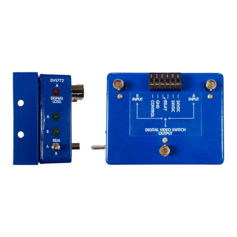
Bracket. Next attach the Primary data signal to the input BNC connector labeled (A INPUT). Then
attach the Secondary data signal to the BNC connector labeled (B INPUT). The BNC connector
labeled (DIGITAL VIDEO SWITCH OUTPUT) is the output of the data switch. The data that is
selected either manually or automatically will appear at this connector. The OUTPUT DATA MUST
HAVE A 75 OHM TERMINATION AT THE END OF THE CABLE. Be sure to terminate the output of
this data switch.
The 6 position snap in screw terminal connector is numbered from left to right, 1 to 6. The
following is a table of the connection inputs and outputs used on this connector. The data switch and
telemetry output is accomplished by internal relay switching. In the event of power loss the data is
switched to the Primary "A" data channel.
1. "CONTROL" Attach contact switch, RS232 +, or TTL +.
2. "GND" Attach contact switch, RS232 -, or TTL -.
3. "RELAY" Telemetry C form relay output 1.
4. "RELAY" Telemetry C form relay output 2.
5. 24 VDC power input + or -, either polarity.
6. 24 VDC power input - or +, opposite polarity.
CONNECTOR BLOCK DIAGRAM
1 2 3 4 5 6
OPERATION
On the front panel there is a Three Position LOCKING SWITCH, to move this switch it is
necessary to PULL OUT THE HANDLE OF THE SWITCH before trying to change its position. DO
NOT FORCE THE SWITCH. There are three command modes for the switch. The first is marked (A),
this will cause the DVS702 to manually force the data switch to the A input source.
The second is marked (B), this position will cause a manual switch to the B input. The third
position is (REM) which stands for REMOTE CONTROL. This position will allow a control signal on the
6 position screw terminal to operate the switch. This signal can be a remote switch contact, RS232, or
TTL signal from other equipment.
DVS702.ISB PAGE2OF3

Inside the unit there are jumper setting that allow the user to program the operating
characteristics of the device. Jumper jacks are used to select the mode of operation. To select a
feature simply connect the jumper jack so that it connects the two gold pins on the feature you want to
select.
SW2 selects the operating characteristic of the input signal connected to terminals 1 and 2 of
the 6 position screw terminal. If SW2 is selected on "NOR" the unit will switch to input B when a
contact is closed or a + voltage is applied to terminal 1 of the 6 position screw terminal.
If SW2 is selected to the "INV" position then the input control is inverted and the unit will switch
to the B channel input when a switch is open or a - appears at the terminal 1 of the 6 position screw
terminal.
If SW2 is selected to the "TOG" position then the input control will toggle between A and B
each time there is a change in the state of terminal 1 of the 6 position screw terminal. Example: if a
switch was connected to control the relay, each time you closed the switch the relay would switch from
one input to the other and back again when the switch was closed again.
The SW5 jumper pins select the C form telemetry relay output. When the jumper is selected in
the "NO" position the output contacts will be open when the data is switched to the A channel. If you
select the "NC" position then the output contacts will be closed when the data is switched to the A
channel. This selector lets you set the output relay telemetry contacts to interface with any other
equipment.
MAINTENANCE
There are no adjustments or calibration required with the DVS702.
DATA SPECIFICATION
Standard SMPTE 310 up to (270Mb) SDTV
Level 800mVpp (typ)
Input Impedance 75 Ohm (non-select input)
Loop-through (select input)
Cross-Talk (270Mb) <50 dB
Front Panel Control Three Position (A, B, and Remote)
Front Panel Indicators Two LED (A, B)
MECHANICAL
Power requirement 24 VDC Power Cube (included)
Current requirement 110 mA
Connectors (Data) BNC (Female)
Connectors (Power and Control) Plug-in Screw Terminal (6 position)
Enclosure 3.5 x 4.5 x 1.5 Die Cast Aluminum
Mounting Side Rack Mounting Bracket
DVS702.ISB PAGE3of3
Table of contents
Other FM Systems Switch manuals
Popular Switch manuals by other brands

Aeon Labs
Aeon Labs Aeotec Micro Smart Energy Switch G2 manual
socomec
socomec SIRCOVER PV 200A manual
Tyco Electronics
Tyco Electronics 8 Port 10/100Mbit/s Ethernet Smart Switch with Fibre... Product user guide
StarTech.com
StarTech.com ST4100USB installation manual
Atlona
Atlona Omega AT-OME-EX-KIT installation guide
Cisco
Cisco Catalyst 4500e Series installation guide

