DESCRIPTION
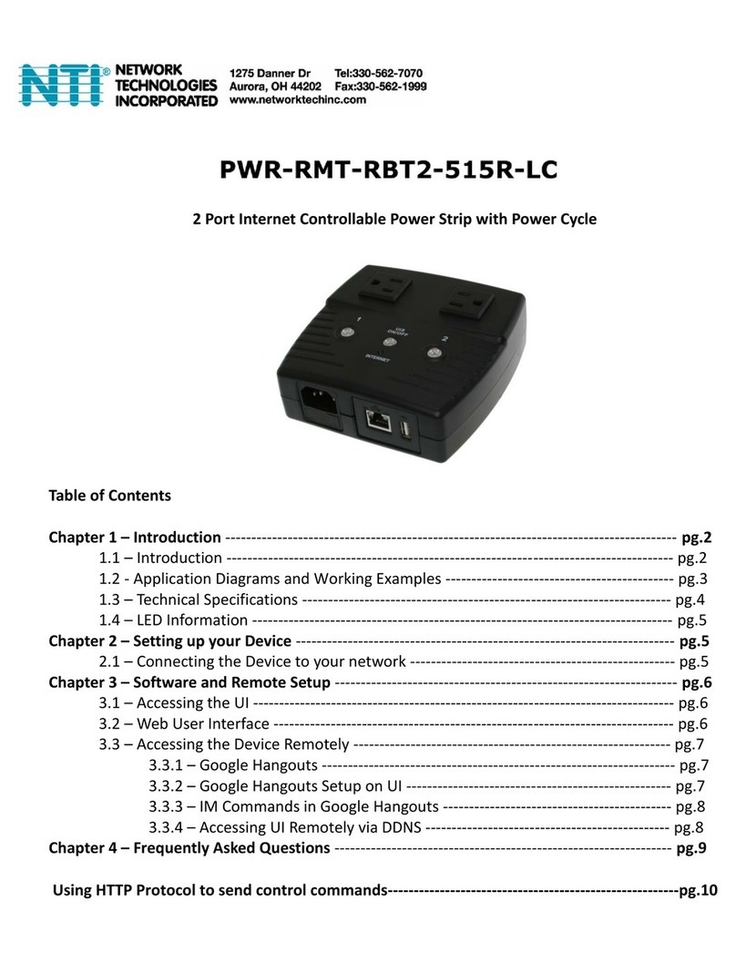
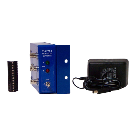
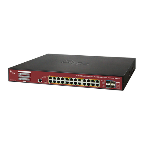
The IPX A/B switch monitors the communications path on any IP network and
automatically switches to an alternate network path when a loss of signal occurs on the primary
path. This network switch will identify the loss of any IP data signal due to removal of an IP
camera or modem, loss of power, a cable disconnect, or a defective camera or modem output.
The unit detects the loss of data communication on the network for any reason such as power
loss, or equipment failure, broken shorted or disconnected wire cables and tampering of any kind.
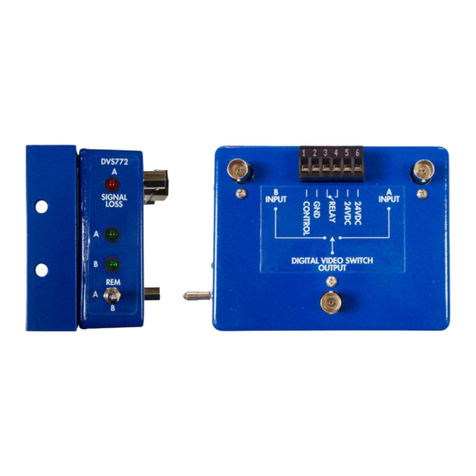
The IPX continuously displays the Data condition of the primary network with an L.E.D. indicator
and a relay contact output for external alarms or it can be jumper programmed for a low voltage
DC output to control other equipment relays. Use it to monitor your IP cameras or any IP network
signal and switch to a secondary source for continuous data communications.
Normally Open or Normally Closed Alarm contacts are provided to send an alarm or
activate equipment when loss of data on the primary network occurs. These contacts are field
programmable for Normally Open or Normally Closed contact operation. Connect this unit to a
local alarm panel to alert monitor personnel that a network is being tampered with or send a
message to a remote site by connecting the alarm output to external dialing equipment. The
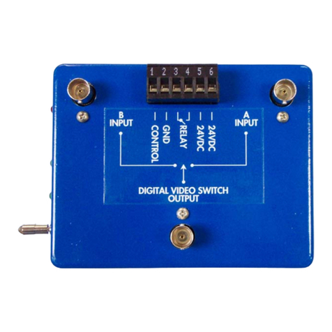
A/B relay switch inputs and output are all accessible to match any switching configurations. This
allows you to monitor one network and switch a completely different network if you need to.
The IPX A/B switch can be connected anywhere in the network path where an alternate
network path is available. The "High Impedance Loop through Input" will not affect the data signal
even if the power fails and it passes the P.O.E. Power Over Ethernet on all wires of the active
channel. P.O.E is disconnected on the failed data path.
Use this unit in any network installation that requires guaranteed continuous
communication. The IPX has an easy mounting flange that will mount to any surface with just two
screws and is supplied with a 12 VDC power cube.
MOUNTING INSTRUCTIONS
The rugged one piece mounting structure allows you to mount the unit firmly in place with
two screws. Select a place to mount the unit away from harsh or wet environments indoors is
recommended. The IPX should be located near the monitor equipment or anywhere along the
path of the IP video signal. Select a position that gives you the best access to cable the system
and reduce the labor in installation.
HOW TO CABLE THE IPX
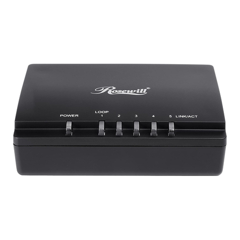
Attach the cable coming from the camera to one of the IP Video 8P8C (RJ-45) connectors
marked “A” on the detector side of the unit. The “A” connectors loop through so you can use either
one for the input or output. Next for a conventional installation attach a short jumper cable from
the other IP Video 8P8C (RJ-45) connector marked “A” on the detector to the “A” port on the
switch side of the unit. Then connect the secondary network source to the “B” connector on the
switch. Then connect the “COM” output of the switch to your network equipment to complete the
data path.
IPXisb PAGE2OF4


