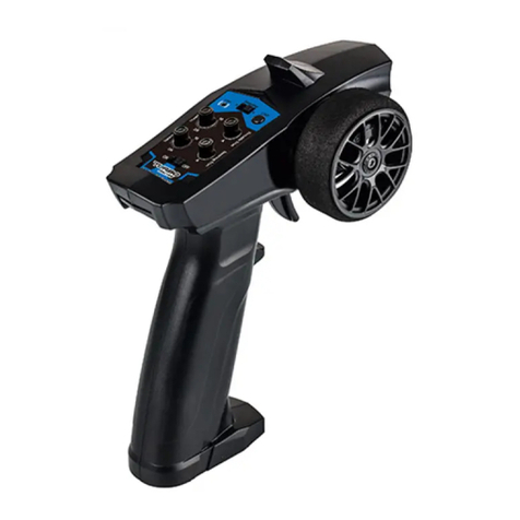
FMA Direct T-80RF User manual

T- 8 0 R F
4-channel microcomputer FM radio control transmitter
User’s guide
Note: Read this manual carefully before operating this product.
FMA, Inc.
5716A Industry Lane
Frederick, MD 21704
Sales: (800) 343-2934 zTechnical: (301) 668-7614
www.fmadirect.com

T-80RF user’s guide – 2 – FMA Direct
Thank you for purchasing the FMA Direct T-80RF radio control
transmitter. This unit provides narrowband FM output with
PPM encoding for radio controlled aircraft and surface craft
(boats, cars and hovercraft). The transmitter operates on any
72MHz RC aircraft channel (11 through 60) or 75MHz surface
channel (61 through 90) when equipped with an appropriate
crystal. It offers user-selectable positive or negative shift, ena-
bling it to work with any 72MHz PPM receiver on the same
channel. The T-80RF uses the latest microprocessor technology
to control every function of the radio and provide such features
as servo reversing on all channels, tri-rates and elevon/V-tail
mixing.
This manual provides information for setting up and using the
T-80RF transmitter. Please read it carefully before using the
transmitter. The manual contains sections covering:
Safety precautions
Other radio components you’ll need
Identifying transmitter components
Installing the antenna
Powering the transmitter
Setting up the radio system
Conducting a radio system preflight check
Troubleshooting
Introduction T-80RF features
Frequency selection. The T-80RF can transmit on any one
of the fifty 72MHz or 75 MHz channels (11 through 90)
allocated for radio controlled aircraft. One crystal is
provided for the channel you selected when you purchased
the transmitter. (According to F.C.C regulations, you cannot
change the crystal in your transmitter unless you are a valid
holder of an F.C.C. Second Class or First Class Operator’s
License.)
Mixing. The T-80RF can be set to mix elevator and aileron
controls for use with aircraft incorporating elevons (for
example, flying wings) or V-tails. (For best results, center
control surfaces mechanically after trimming in flight.)
Servo reversing. Switches conveniently located on the
front panel change the direction of servo rotation. This
enables you to install servos and linkages in the best
mechanical configuration, then simply change a switch to
obtain the correct direction of motion.
Tri-rates. Tri-rates, set by a switch on the front of the
transmitter, desensitize controls while you are learning to fly
(beginners tend to over-control). The T-80RF provides 50%
and 75% throws (in addition to the full 100% throw)
simultaneously on the aileron, elevator and rudder channels.
The T80RF is particularly useful for reducing the throw on
small aircraft using short control horns.
Trims. Each of the four channels has a trim adjustment to
compensate for variations in the model and local flying
conditions.
Battery indicator. Transmitter battery status is displayed
when the transmitter is on, enabling you to check for safe
battery power level at a glance.
Selectable frequency shift. The T-80RF can be used with
any narrowband FM PPM receiver you already own.
Ergonomic design. Ribbed case and concave stick tips give
you a solid grip on the transmitter and controls, allowing
you focus on smooth and safe operation of your model.
Recessed power switch helps prevent accidental shut-off.
Function 4-channel computer-controlled FM radio control transmitter
Size 6.75" wide x 2.6" deep x 6.25" high (including handle, not including antenna)
Weight 15.6 oz. (without batteries)
Frequencies All U.S. 72 and 75 MHz radio controlled aircraft frequencies: Channel 11 through Channel 90
Power 8 AA alkaline batteries or optional 8-cell, 600 milliamp NiCad battery pack
Current drain 185 milliamps
RF output power 400 milliwatts
Encoding PPM (universal, selectable positive or negative shift)
Operating pulse width 1.0 milliseconds to 2.0 milliseconds (1.5 milliseconds neutral) on each channel
F.C.C. ID KH8-RFD1
T-80RF specifications
2001 FMA, Inc. All rights reserved. Reproduction of this publication is prohibited. User Guide Version 2.0 10/9/2001

FMA Direct – 3 – T-80RF user’s guide
Safety precautions
Radio controlled models are not toys! Please observe these
safety precautions:
Follow all instructions in this manual to assure safe
operation.
If you have not assembled and operated a radio controlled
model before, obtain help from an experienced modeler.
You will need guidance to successfully assemble, test and
operate radio controlled models. One of the best ways to
obtain help is to join your local radio control club.
Never fly radio controlled airplanes near people, buildings,
telephone or power lines, cars, trees or other objects on the
ground or in the air.
Keep your radio controlled models and equipment away
from children. Do not allow unauthorized people of any age
to operate radio controlled models without proper
supervision from an experienced modeler.
In some areas of the country, you cannot legally operate
radio controlled models except at approved fields. Check
with local authorities first.
Observe frequency control. If someone else is operating a
radio controlled model on the same channel as your
transmitter, do not turn on your transmitter—even for a
short time. Your transmitter’s channel number is marked
on the crystal cover (see next page). When a model receives
signals from two transmitters on the same channel at the
same time, it cannot be controlled and will crash—possibly
causing personal injury or property damage. For safety,
most RC flying fields have formal frequency control
rules. Follow them carefully.
Do not operate your radio control transmitter within 3 miles
of a flying field. Even at a distance, your transmitter can
cause interference.
Do not operate radio controlled models and equipment in the
rain, or at night.
Protect all electronic equipment from exposure to rain,
water, high humidity and high temperatures.
Discard batteries in accordance with local waste disposal
and recycling regulations.
FMA Direct recommends that you join the AMA. They can
help you find a club in your area.
Academy of Model Aeronautics
5161 East Memorial Drive
Muncie, Indiana 47302
Phone: (800) 435-9262
Web: www.modelaircraft.org
Besides the T-80RF transmitter, you’ll need:
Receiver, operating on the same radio control channel as the
transmitter.
Switch harness.
Servos for moving aircraft control surfaces.
Optional extension cable for connecting aileron servo to
receiver.
For an engine-powered aircraft: additional servo (for
controlling engine speed), and battery pack to supply power
to receiver and servos.
For an electric motor-powered aircraft: electronic speed
control (for controlling electric motor speed and supplying
power to receiver and servos).
Other radio components you’ll need
Tip: FMA Direct carries a full line of compatible receiv-
ers, servos, electronic speed controls, battery packs,
chargers and related flight equipment.
1. Locate the end of the antenna having the threaded hole.
2. Gently slide that end of the antenna into the antenna hole in
the top of the transmitter, until the antenna can’t be slid in
any farther (don’t force it).
3. Gently rotate the antenna clockwise (as seen from the top).
Stop rotating when the antenna is secure.
Installing the antenna

T-80RF user’s guide – 4 – FMA Direct
Identifying transmitter components
Antenna
Carrying handle
Battery condition indicator
Left stick
Power switch Neck strap hook
Trims
NiCad battery charging jack
Servo reversing switches
Function switches: mixing, tri-rates
and positive/negative shift
Crystal cover
Note: Look here for your
transmitter’s channel number
Right stick

FMA Direct – 5 – T-80RF user’s guide
The T-80RF can be powered either by alkaline batteries or by
an optional rechargeable NiCad battery pack. You selected
the type of power when you purchased the transmitter. Fol-
low the instructions on this page for your power system.
Installing alkaline batteries
1. Remove the battery cover: push inward on the cover where
it is marked “Push,” then slide the cover toward the
bottom of the transmitter.
2. Install 8 fresh AA alkaline cells according to the polarity
markings in the battery compartment.
3. Replace the battery cover: position the cover over the
battery chamber, insert the cover tabs into the slots in the
transmitter body, then slide the cover toward the top of the
transmitter.
1. Turn the T-80RF on by sliding the power switch to the up
position.
2. Observe the battery condition indicator light (just above
the power switch):
3. Turn the T-80RF off by sliding the power switch to the
down position.
Powering the transmitter
Tip: Alkaline batteries should last for about 10 hours
of operation. Take an extra set to the flying field, in
case the set in the transmitter becomes unusable.
Using the optional NiCad batteries
If you ordered the NiCad battery option, the battery pack was
installed at the factory and you do not need to install it. How-
ever, you must charge the battery pack for 24 hours before us-
ing the transmitter for the first time. Charge the battery pack
using the included charger.
Charging the NiCad batteries
1. Turn off the T-80RF by sliding its power switch to the down
position.
2. Connect the charger’s transmitter connector to the Charge
jack on the front of the T-80RF.
3. If you also need to charge a receiver battery pack, connect
the charger’s receiver connector to the pack.
4. Plug the charger into a standard 120VAC wall outlet. If the
batteries are properly connected and charging, the charger’s
corresponding indicator light will glow.
5. Before first use, charge the batteries for 24 hours. Then,
before each flying session, charge the batteries for 10 to 12
hours.
Caring for NiCad batteries
NiCad batteries, if properly maintained, will provide long life.
About once per month, you should fully discharge NiCad bat-
teries, then fully charge them. This helps prevent NiCad
“memory” effects, which can lead to lower capacity and false
indications of proper charge level.
Tip: After initial battery charging, a field charger can
recharge transmitter, receiver and/or flight pack NiCad
batteries in as little as 20 minutes from a 12 volt stor-
age or automobile battery. This is convenient when
you need to charge batteries and there isn’t a 120VAC
outlet nearby to supply power for a wall plug-in type
charger. The FMA Direct catalog lists several peak-
detecting field chargers (or visit www.fmadirect.com on
the Web). Please read and follow the instructions that
come with your field charger before fast-charging any
battery pack.
Tip: FMA Direct offers battery management systems
that help keep batteries in top condition.
Note: The NiCad battery pack is permanently installed
in the T-80RF. If it needs to be replaced, please return
the T-80RF to an FMA service center.
Note: Check the battery indicator periodically during
each session. If you are flying an airplane and the bat-
tery indicator turns red, land the plane immediately.
Green Transmitter is ready for use.
Yellow Batteries are approaching a depleted state.
Avoid using the transmitter until batteries have
been replaced or recharged.
Red Batteries are depleted, and must be replaced or
recharged before you can use the transmitter.
No color Batteries are dead, and must be replaced or
recharged before you can use the transmitter.
Note: You cannot charge the T-80RF NiCad battery
pack if the transmitter is on.
Determining battery condition
CAUTION: If you are at or near a flying field, ob-
serve frequency control rules and comply with local
procedures before turning on your transmitter. When
the transmitter is on—even for a few seconds, it is
radiating radio frequencies which may interfere with
a radio system already operating on the same fre-
quency.

T-80RF user’s guide – 6 – FMA Direct
Setting up the radio system
A. Set transmitter frequency shift.
The T-80RF works with any narrowband FM receiver with
PPM decoding. You must, however, set the transmitter’s fre-
quency shift to match the receiver you will be using. Check the
receiver’s specifications to determine whether it uses positive or
negative shift. Universal receivers can be set to either positive
or negative shift, so check the receiver to determine its configu-
ration.
1. Locate the PPM switch in the Functions section on the T-
80RF front panel.
2. Set the switch as follows:
B. Set mixing.
If your airplane is equipped with elevons or a V-tail, you’ll need
to activate mixing. If your plane has conventional controls
(ailerons, elevator, rudder), mixing must be off.
1. Locate the Mix switch in the Functions section on the
T-80RF front panel.
2. Using a very small flat-blade screwdriver, set the Mix
switch as follows:
CAUTION: Be sure to check and, if necessary,
change the PPM frequency shift setting when using a
different receiver.
For a... such as... move switch...
Negative shift
receiver
FMA, Futaba, Hitec
and most others
Down (off)
Positive shift
receiver
JR, Airtronics/Sanwa Up (on)
Note: If your flying wing or V-tail aircraft is equipped
with an electronic mixer, set T-80RF mixing to off.
CAUTION: Be sure to check and, if necessary,
change the Mix switch when you use the transmitter
with a aircraft having a different control configuration.
For... set Mix switch...
Conventional controls (ailerons,
elevator, rudder) or electronic mixer in
aircraft
Down (off)
Elevons or V-tail Up (on)
About mixing
The T-80RF has 50-50 bi-directional mixing between the eleva-
tor and aileron channels. For each degree of elevator motion,
the aileron channel moves an equal amount. And for each de-
gree of aileron motion, the elevator moves an equal amount. In
the model, two servos move the elevons or V-tail surfaces. With
this kind of control configuration, the servos are called the right
servo and left servo (instead of aileron servo and elevator
servo).
With mixing, when you move the transmitter’s elevator stick, the
control surfaces move to make the airplane go up or down.
When you move the transmitter’s aileron stick, the control sur-
faces move to make the airplane yaw/roll left or right.
Tip: Mixing frees the rudder channel for another func-
tion. You could, for example, use the rudder channel
for flaps, retracts, to drop a parachute or push the
shutter button of an on-board camera.

FMA Direct – 7 – T-80RF user’s guide
C. Set the control throws.
Control throw refers to how far an airplane’s control surfaces
move in response to the maximum movement of the corre-
sponding control stick on the transmitter. You must set control
throws with the T-80RF’s tri-rate at 100%.
1. Install the servos, linkages, receiver, switch harness and
receiver battery in the aircraft according to instructions
supplied with those items. (If you purchased an FMA flight
pack, refer to the manual supplied with it.)
2. Be sure the servos are connected to the receiver as follows:
3. Locate the 50% and 75% switches in the Functions section
on the T-80RF front panel.
4. Using a very small flat-blade screwdriver, move the 50%
and 75% switches to the down (off) position. This sets the
tri-rate feature to 100% so you can initially set up the
control surfaces.
5. Set all four transmitter trims to their centered positions.
6. Turn on the transmitter, then turn on the receiver.
7. With the transmitter control sticks centered, make sure that
the control surfaces are in their neutral positions. If a
control is offset from neutral, adjust the appropriate linkage.
8. Set each control surface to the amount of travel
recommended by the airplane’s manufacturer. Do this by
changing the location of the clevis in the servo arm and/or
control horn holes.
Example: If the manufacturer specifies a 1/2" control throw
for the elevator, then the elevator trailing edge should move
1/2" up or down from its neutral position when you move
the transmitter’s elevator stick all the way up or all the way
down.
9. Using the table below, set the tri-rate to match your skill
level. If you are a beginner, ask your instructor for advice
(the instructor may want to test the aircraft at 100%, then
select a different setting before letting you control the
Setting up the radio system — continued
Note: At this point, don’t use the transmitter trims to
set control surfaces to their neutral positions—make
only mechanical adjustments in the linkages. This
assures that the servos and their corresponding con-
trol surfaces are in their neutral positions at the same
time.
For this skill level... set
50% switch...
and set
75% switch...
Beginner (50% rate) Up (on) Down (off)
Intermediate (75% rate) Down (off) Up (on)
Advanced (100% rate) Down (off) Down (off)
Connect this servo... to this FMA receiver* channel...
Elevator 1
Aileron 2
Throttle or
speed control
3
Rudder 4
*If used with receivers from other manufacturers, channel order
may be different. Check your receiver’s manual for channel as-
signments. If you aren’t sure about channel assignments: a) plug
one servo into one receiver channel, and move the transmitter
sticks to determine which stick is associated with that channel, then
b) move the servo to other channels and repeat.
Note: The 50% and 75% tri-rates simultaneously
desensitize the aileron, elevator and rudder controls.
CAUTION: If you are at or near a flying field, ob-
serve frequency control rules and comply with local
procedures before turning on your transmitter. When
the transmitter is on—even for a few seconds, it is
radiating radio frequencies which may interfere with
a radio system already operating on the same fre-
quency.

T-80RF user’s guide – 8 – FMA Direct
D. Set control throw directions (servo reversing).
You must assure that the aircraft’s control surfaces and throttle
move in the correct directions. If they move in the incorrect di-
rections, you will not be able to control your airplane.
1. Turn on the transmitter, then turn on the receiver.
2. Move each control stick on the transmitter, and compare the
airplane’s control surfaces and throttle with the pictures on
this page and the next page (depending on your airplane’s
configuration).
3. If a surface or the throttle moves in the wrong direction, use
a small flat-blade screwdriver to change the position of the
corresponding channel switch in the Reverse section of the
transmitter’s front panel. Check control movement again.
Setting up the radio system — continued
Conventional controls
Rear view
Rear view
Roll control (aileron, channel 2*)
Roll right
Roll left
Rear view
Rear view
Pitch control (elevator, channel 1*)
Pitch up
Pitch down
Rear view
Rear view
Yaw control (rudder, channel 4*)
Yaw right
Yaw left
CAUTION: If you are at or near a flying field, ob-
serve frequency control rules and comply with local
procedures before turning on your transmitter. When
the transmitter is on—even for a few seconds, it is
radiating radio frequencies which may interfere with
a radio system already operating on the same fre-
quency.

FMA Direct – 9 – T-80RF user’s guide
Setting up the radio system — continued
*Note: Channels assignments are for the T-80RF
and correspond to the servo reversing switches.
Elevon controls V-tail controls
Throttle control (channel 3*)
Idle
Full speed
Rear view
Rear view
Roll control (channel 2*)
Roll right
Roll left
Rear view
Rear view
Pitch control (channel 1*)
Pitch up
Pitch down
Rear view
Rear view
Roll control (channel 2*)
Roll right
Roll left
Rear view
Rear view
Pitch control (channel 1*)
Pitch up
Pitch down
Note: Stick movements and control throws shown
on these pages are exaggerated for clarity. Nor-
mal flying requires only small stick movements.

T-80RF user’s guide – 10 – FMA Direct
Before starting and flying any aircraft, you should perform a
thorough preflight check of the propeller, engine/motor, air-
frame, control surfaces, linkages and many other parts. Details
are beyond the scope of this manual, but the steps below cover
typical radio system check-out.
1. Check receiver battery voltage with an extended range
voltmeter. (A standard voltmeter isn’t effective for checking
receiver batteries. An extended range voltmeter applies a
load, which simulates typical use conditions for more
accurate measurement of battery voltage.)
2. Assure servos, switch harness and receiver battery are
securely connected.
3. Assure receiver antenna is deployed.
4. Assure transmitter antenna is secure. Tighten if necessary.
5. Extend transmitter antenna to its full length.
6. Check transmitter battery condition: turn on the transmitter
and observe the battery indicator above the power switch. If
it is green, the transmitter is ready to use.
7. Check tri-rate switches to assure they are set to match your
skill level.
8. Turn on receiver.
9. Check for proper control directions: move all four
transmitter sticks—one at a time—and observe the
corresponding control surfaces and throttle. Change servo
reversing and/or mixing settings as needed.
10.Assure control linkages move freely. Correct any linkage
binding. (Binding linkages can rapidly deplete the receiver
battery.)
11. Perform a range check to assure the airplane can be safely
controlled by the transmitter at a distance. (If you don’t
know how to perform a range check, ask your instructor or
get help from an experienced modeler. FMA flight pack
manuals contain range check distances.)
After starting the engine and before taking off, check the con-
trols again. Engine vibration may reveal loose connections or
other radio system problems. If the radio system doesn’t per-
form perfectly, stop the engine and correct any problems.
Conducting a radio system preflight check
CAUTION: If you are at or near a flying field, ob-
serve frequency control rules and comply with local
procedures before turning on your transmitter. When
the transmitter is on—even for a few seconds, it is
radiating radio frequencies which may interfere with
a radio system already operating on the same fre-
quency.
Many “shootdowns” occur during pre-flight
checks. You must coordinate with other flyers so
that two transmitters are never transmitting on the
same channel at the same time.
About FMA
FMA, Inc. has been designing innovative radio control elec-
tronics for more than 30 years. FMA designs are known for
their high quality and reliable performance. Since 1994, FMA
Direct has assembled an impressive line of more than 300 radio
control products available through dealers and directly from the
company, backed up by solid customer support. Please visit the
FMA Web site (www.fmadirect.com) for the latest information
about our products.
Products available from FMA Direct include:
Dual conversion receivers: 4, 5, 6 and 8 channels; sub-
micro, micro and standard sizes; 72MHz, 75MHz and 6
meters.
Servos: micro, mini, standard and high torque.
Flight packs: including receiver, servos and battery pack or
speed control.
Electronic speed controls: for RC cars, airplanes and boats.
Electric motors and propulsion systems.
Field chargers and battery management systems.
Electric airplanes: including the Razor flying wing.
Battery packs: for receivers, transmitters and electric flight.
And many other radio control components and accessories.

FMA Direct – 11 – T-80RF user’s guide
Transmitter troubleshooting
Symptom Possible cause
Battery indicator doesn’t light up. Batteries are dead.
Controls chatter during range check. Transmitter antenna is loose.
Transmitter battery doesn’t have enough power.
Receiver battery doesn’t have enough power.
Servo or battery connectors not securely connected to receiver.
Control operates wrong direction. Servo reversing switch is set incorrectly.
Aileron control moves both ailerons and elevator.
Elevator control moves both elevator and ailerons.
Mixing for elevon/V-tail is activated, but model has conventional controls.
Unexpected or uncommanded control excursions.
Someone else is transmitting on the same frequency. Do not fly until the
frequency is clear.
Battery charger connected and plugged in, but not
charging.
Transmitter is on.
Warranty
FMA, Inc. warrants this product to be free of manufacturing defects for the term of one year from the date of purchase. Should any
defects covered by this warranty occur, the transmitter shall be repaired or replaced with a unit of equal performance by FMA, Inc.
or an authorized FMA service station.
Limits and exclusions
This warranty may be enforced only by the original purchaser, who uses this product in its original condition as purchased, in strict
accordance with the product’s instructions. Units returned for warranty service to an FMA service center will be accepted for ser-
vice when shipped postpaid, with a copy of the original sales receipt or warranty registration form, to the service station designated
by FMA, Inc.
This warranty does not apply to:
Consequential or incidental losses resulting from the use of this product.
Damage resulting from accident, crashes, misuse, abuse, neglect, electrical surges, reversed polarity on connectors, lightning or
other acts of God.
Damage from failure to follow instructions supplied with the product.
Damage occurring during shipment of the product either to the customer or from the customer for service (claims must be pre-
sented to the carrier).
Damage resulting from repair, adjustment, or any alteration of the product by anyone other than an authorized FMA technician.
Installation or removal charges, or damage caused by improper installation or removal.
Call (301) 668-7614 for more information about service and warranty repairs.
FMA limited warranty on transmitter products

Table of contents
Other FMA Direct Remote Control manuals
