FUTABA 6DA User manual

Instruction Manual
Thank you for purchasing the Futaba 6DA 6-channel with Flight Set radio system. Whether this is your first
R/C radio system, or you’re moving up or replacing a trusted old friend, we believe you’ll be pleased with
your 6DA. Futaba is the leader in R/C radio technology.
Please read this instruction manual carefully and use the 6DA radio system safely. If you are unfamiliar with
some of the terms in this instruction manual, take a few minutes to read the glossary. It contains useful
information about terms that will help you understand the functions and features of this radio. Save this
manual for future reference and, most of all, have fun!
Entire Contents © Copyright 2001 FUTZ8570 V1.0
Safety Information ......................2
Features & Specifications ............6
Battery Care ................................7
Installing Servos ..........................7
Setting Up Your Radio Gear ........8
Transmitter Operation...............10
Servo Reversing .........................11
Throttle EPA ..............................12
AST's .........................................13
Dual Rates.................................14
Aileron-to-Rudder Mixing .........15
Dual Aileron Servos/Flaperons ..16
Aileron Differential ...................17
Retractable Landing Gear..........18
Flaps..........................................19
Flap-to-Elevator Mixing .............19
Trainer Function........................20
Prepare to Fly............................20
Glossary ....................................21
Troubleshooting Guide..............23
Radio System
•No part of this manual may be reproduced in any form without prior permission.
•The contents of this manual are subject to change without prior notice.
•This manual has been carefully written. Please write to Futaba if you feel that any corrections or clarifications should be made.
•Futaba is not responsible for the misuse of this product.
Warranty
The US Futaba Service Center will warranty this radio for one year after the purchase date from defects
in materials or workmanship. Please read the enclosed Futaba Warranty Card for full details of this
radio’s warranty.
Make sure you save the receipt or invoice you were given when you bought your radio! It is your
proof of purchase and we must see it before we can honor the warranty.
To return your radio for repairs covered under the warranty, or for non-warranty service, please ship it with
a detailed explanation of your concerns to the address listed below. Please include as many means of
contact as possible. Daytime fax number and email address will allow us to provide you automated
information updates, and will assist the service team in contacting you as quickly as possible.
Futaba Service Center
1610 Interstate Drive
Champaign IL 61822
www.futaba-rc.com
phone: 217-398-0007
8:00am - 5:00 pm Central Time M-F
fax: 217-398-7721
email: [email protected]

223
To ensure safe use, observe the following precautions.
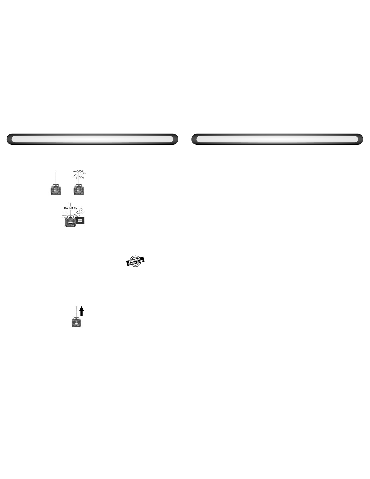
Precautions During Flight
• Do not fly or turn on simultaneously with
another radio on the same frequency.
Interference will cause
a crash. Use of the
same frequency will
cause interference
even if the modulation
method (AM, FM,
PCM) is different.
• Do not fly on rainy or
windy days, or at night.
Water will penetrate into the
transmitter (Tx) and cause
faulty operation, or loss of
control, and cause a crash.
Do not fly in the following places:
• Near other R/C flying fields (within about
2.5 miles [4km]).
• Near people on the ground, or objects in
the air.
• Near homes, schools, hospitals, or other
places where there are a lot of people.
• Near high tension lines, high structures,
or communication facilities. Radiowave
interference and obstructions may cause a crash. A
crash caused by trouble in the R/C set, or the model
itself, may cause death or property damage.
Other Precautions
• Do not fly when you are tired, sick, or
intoxicated. Fatigue, illness, or intoxication will
cause a loss of concentration or normal judgment
and result in operation errors and a crash.
• Extend the antenna to its full
length. If the antenna is shortened,
the effective range of the radio signal
will be shorter.
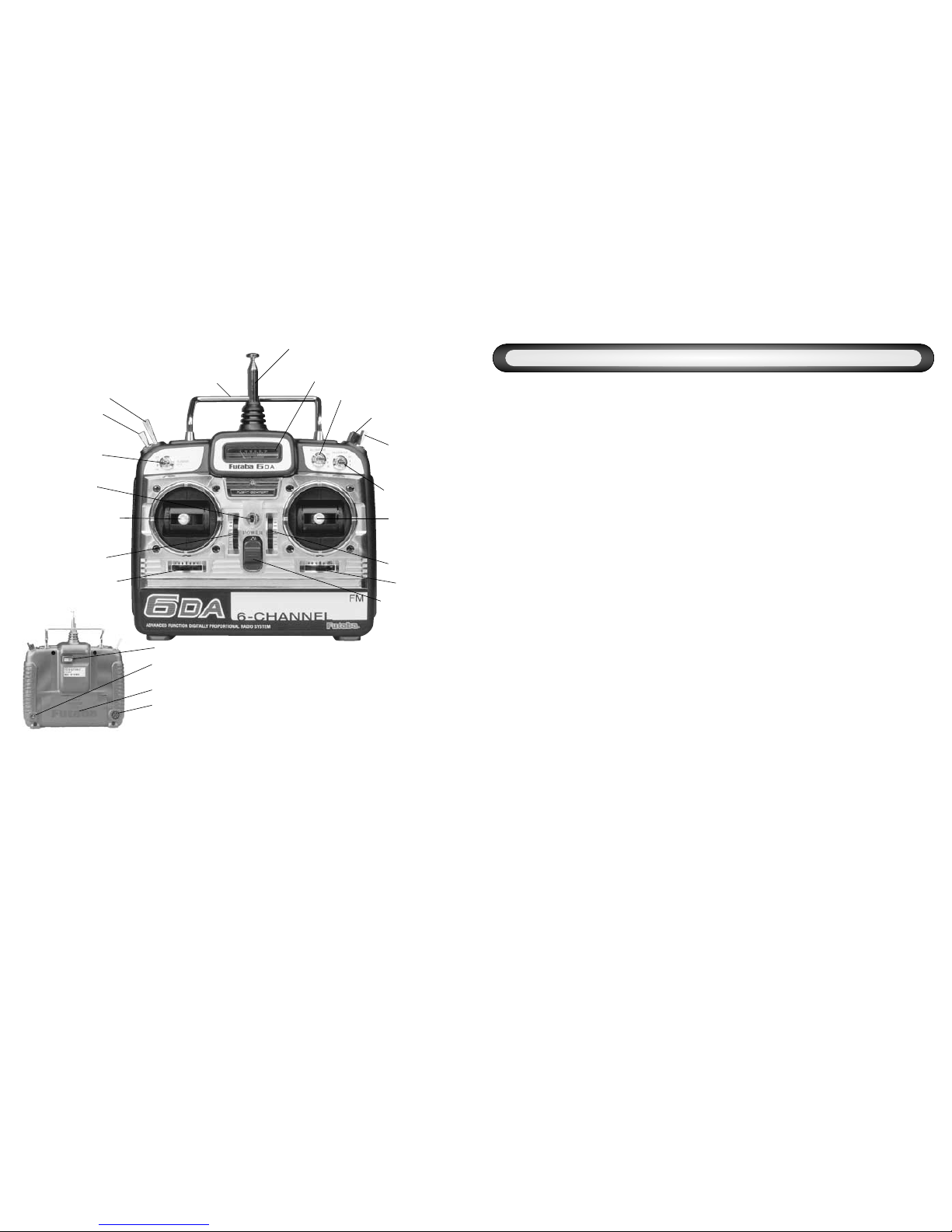
• Check that the transmitter (Tx) antenna is
not loose. If the transmitter antenna comes off
during use, control will be lost and the model
will crash.
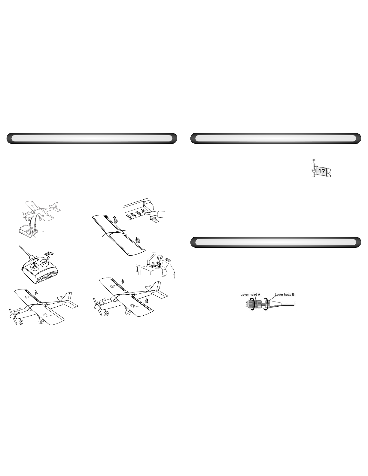
• Always test the R/C set before use. Any
abnormality in the R/C set, or model, may cause a
crash. Before starting the engine, check that the
direction of operation of each servo matches the
operation of its control stick. If a servo does not move
in the proper direction, or operation is abnormal, do
not fly the plane.
• When placing the transmitter (Tx) on the
ground during flight preparations, be sure
that the wind cannot knock it over. If it is
knocked over, the throttle stick may be pushed to full
throttle, the engine will speed up and may create a
very dangerous situation.
• When adjusting the R/C set, always stop
the engine. If the engine suddenly goes to full
throttle, it may cause an injury.
• Do not get fuel, oil, etc. on plastic parts.
The plastic may melt, discolor, become brittle and fail
to function.
• Always use Genuine Futaba transmitters,
receivers, servos, ESCs, NiCd batteries,
and other optional parts. Futaba is not
responsible for damage, etc. caused by the use of
parts other than Genuine Futaba parts. Use the parts
described in the instruction manual and catalogs.
NiCd Battery Charging Precautions
Always charge the NiCd batteries before
each flight. If the battery goes dead during flight, the
plane may crash or fly away.
Charge the R/C NiCd battery with the
standard charger, or fast field charger (sold
separately). Overcharging may cause burns, fire,
injury, blindness, etc. due to overheating, breakage,
electrolyte leakage, etc.
Do not short the NiCd battery connector
terminals. Shorting the terminals will cause sparking
and overheating and result in burns or fire.
Do not drop or apply strong shock to NiCd
battery. The battery may short out and cause
overheating or breakage and electrolyte leakage,
resulting in burns or damage from chemical contents.
SAFETY INFORMATION
Problem Possible causes Solution
Short range
Collapsed or loose Tx antenna...........Fully extend the antenna and make sure it is
securely attached
Interference.........................................Check frequencies in area and
check Rx installation
Rx antenna poorly routed ...................Reroute antenna away from other wiring
Severed Rx antenna ...........................Send to Futaba service center for new antenna
Tx or Rx battery not fully charged ......Fully charge batteries prior to use
Rx or Tx out of tune............................Send to Futaba service center for retuning
Crash damage ....................................Send to Futaba service center for inspection and repair
Faulty Rx or Tx crystal ........................Install new crystal and perform range check
Sluggish servo response
Low Tx or Rx batteries........................Fully charge batteries prior to use, may need cycling
(you must remove the batteries from the TX to cycle,
and this requires opening the Tx case.)
Binding servos causing
excess battery drain............................Check pushrods and free binding
Too many servos.................................Use fewer servos if possible, or use a higher capacity
battery pack
Tx meter low
Tx batteries are discharged ................Fully charge batteries prior to use
Tx meter above red zone
but servos do not function
Rx batteries are discharged................Fully charge batteries prior to use
No power to receiver...........................Move Rx switch harness to “ON” position
Switch harness incorrect ....................Make sure all leads are in the proper positions
Reversing switch stuck in-between
positions..............................................Move switch fully to one side or the other
Interference or servos glitching
Another Tx is on your channel............Turn off immediately and do not operate your system
until other user is finished
Outside interference............................Check local R/C club to learn of dangerous frequencies
in your area
Engine or motor electrical noise .........Reroute antenna or servo leads as far away from
engine or motor as possible
One glitching servo
Malfunctioning servo...........................Replace servo
Other interference...............................Check quality and installation of servo lead or extension
Servo movement not as expected
Mix accidentally activated ...................Check all mix dip switches
Servos connected incorrectly..............Check all servo connections
Interference.........................................See above
Too much/Too little throw ....................Check AST and D/R settings and switches
TROUBLESHOOTING GUIDE

22 3
Retractable Gear - Landing gear which can
be drawn up into the aircraft during flight.
Retract Servo - A specialized servo which
only travels to full deflection and is not
proportional. When input is given, the servo
moves from one extreme to the other, which,
when installed properly, will either bring the
retractable gear all the way up and hold it in place,
or lower it completely and hold it down.
Rudder (RUD) - Tail control surface, attached
to the vertical fin, that controls the direction of
the aircraft.
Reverse (REV) - For the servo reversing
function, this refers to the reverse side. The
opposite side of reverse is the normal side.
Roll - The rotation of the aircraft’s wing tips up or
down.
Servo Horn - A plastic part installed to the shaft of
a servo which changes the rotating motion of the
servo to linear motion. A linkage is hooked to this to
transmit motion to the surface.
Servo Reversing - Changes the direction in
which the servo travels.
Stick - A Control providing input to the transmitter.
Throttle (THR) - Controls the fuel/air mixture of
the engine. When opened (throttle high position), a
large fuel/air mixture is sucked in and the engine
speed increases. When closed (throttle low position),
the engine speed decreases.
Throw - The distance a control surface moves in
response to movement of the transmitter stick.
Trainer Function - An electronic feature which
allows two transmitters to be connected by an
optional cord. Allows instructor to give and regain
control from the student.
Trim - A device that adjusts the neutral point of
each servo. In the case of the throttle, the trim
adjusts only the low end of the travel.
Up - (“up” elevator) The direction in which the
trailing edge of the control surface moves.
Yaw - The rotation of the aircraft’s nose to the left
or right.
Storage and Disposal Precautions
Do not leave the R/C set, battery, model
airplane, etc. within the reach of small
children. Touching and operating the R/C set, or
licking the battery, may cause injury or damage due to
chemical content.
Do not throw the NiCd battery into a fire or
heat the NiCd battery. Also, do not
disassemble or rebuild the NiCd battery.
Breakage, overheating, and electrolyte leakage may
cause injury, burns, or blindness.
NiCd Battery Electrolyte
The electrolyte in a NiCd battery is a strong alkali and
can cause blindness if it gets in the eyes. If you get the
electrolyte in your eyes, immediately wash your eyes
with water and see a doctor. If you get the electrolyte on
your skin or clothes, it may cause a burn. Immediately
wash it off with water.
Do not store the R/C set in the following
places:
• Where it is very hot (75°F [40C] or more)
or very cold (18°F [-10C] or less).
• Where the set will be exposed to
direct sunlight.
• Where the humidity is high.
• Where there is strong vibration.
• Where it is dusty.
• Where there is steam and heat.
Storing the R/C set in the places listed above may
cause distortion, corrosion and product failure.
If the R/C set will not be used for a long
time, remove the NiCd batteries from the
transmitter and the model and store them
in a dry place.
If the batteries are left in the transmitter and model, the
battery electrolyte may leak out and damage the
system, degrade the performance and shorten the life of
the transmitter and model.
NiCd Battery Recycling
(for North America only)
Used NiCd batteries are an important resource. Stick
tape over the terminals and take the used batteries to a
NiCd battery recycling center.
The RBRC Battery Recycling Seal on
the nickel-cadmium (NiCd) battery
that should be used in our product
indicates Futaba is voluntarily
participating in an industry program
to collect and recycle these batteries
at the end of their useful life, when
taken out of service in the United States or Canada. The
RBRC program provides a convenient alternative to placing
used NiCd batteries into the trash or the municipal waste
system, which is illegal in some areas. Please call 1-800-822-
8837 for information on NiCd battery recycling in your area.
Futaba’s involvement in this program is part of our
commitment to preserving our environment and conserving
our natural resources.

21
Adjustable Servo Travel (AST) - An
electronic adjustment of how far a servo moves when
full inputs are given. Allows fine-tuning of the
deflection provided to the control surface after
adjusting the linkages as closely as possible.
Sometimes called ATV. Note: AST has only one pot
which adjusts both ends of travel simultaneously.
Aileron (AIL) - Control surfaces on the left and
right sides of the main wing. These surfaces
control banking (rolling) of the aircraft.
Aileron Differential (AIL/DIFF)- An electronic
or mechanical setup which results in less down travel
than up travel on each aileron servo to correct for
unwanted yawing or “barrel rolling” effects when
aileron input is given.
Binding - A problem with control linkages where
the surface does not move freely or where the
servo is attempting to push the surface farther
than it can physically go. This problem is frequently
noticeable due to a loud humming or “buzzing” of
the servo.
Channel -
• The frequency on which an aircraft’s radio
equipment is transmitting.
(ex. Ch. 11 is 72.010MHz)
• The number of servos the radio can
independently control. The 6DA is a 6-channel
radio, so it can independently operate 6 servos
in a model.
• The receiver slot into which a servo is plugged
in a receiver to operate a particular function. For
example, a single aileron servo is plugged into
channel 1, also called slot 1. Its counterpart in a
dual aileron servo setup is plugged into channel
6, also called slot 6.
Control Surface - A moveable portion of the
Fin, Stabilizer or Wing that produces changes in
the aircraft’s path of flight.
Down -(“down” elevator) The direction in which the
trailing edge of the elevator moves.
Dual Rate (D/R) - An electronic adjustment
which reduces servo travel when activated.
Elevator (ELE) - Control surface that moves up
and down on the horizontal stabilizer of an aircraft
and controls pitch.
End Point Adjustment (EPA) - An
electronic function which allows for independent
adjustment at each end of servo travel. Sometimes
called ATV.
Flaperon - Twin aileron servo function, with one
servo operating each aileron, which provides
normal aileron function when aileron input is given
and also moves both ailerons in unison to operate
as flaps when flap input is given.
Flap (FLP)- A single control surface across the
center or a pair of matched control surfaces, one
on each side of the wing which, when lowered,
slows the aircraft down, increases lift and allows
the aircraft to fly at slower speeds.
Linkage - Mechanism that connects the servos
to the control surfaces. Includes pushrods,
clevises, control horns and servo arms.
Mix - An electronic action within a transmitter
which commands a second servo to operate in
direct proportion to the control movement of the
primary servo.
Normal (NOR) - For the servo reversing
function, it is the normal side. The opposite side is
the reverse side.
Pitch - The rotation of the aircraft’s nose up
or down.
4
GLOSSARY
Power switch: Turns the transmitter “On” or “Off.” In the
upper position, the power is “On”.
Voltage indicator: This is an expanded scale voltmeter. It is
not calibrated in volts. When the needle deflects to the
boundary between the silver and red zones or lower,
recharge or replace the battery. Do not operate the
transmitter if the needle descends into the red area.
Removable Antenna: Radiates signal to the receiver.
Never operate the transmitter without extending this
antenna or you may create interference to other modelers
and decrease your control of your model.
Aileron, Elevator, Throttle and Rudder sticks: Controls
designated function. See page 10 for the transmitter
operation instructions.
Aileron, Elevator, Throttle and Rudder trim levers: Used
to shift the neutral or idle position of each servo. (As the
throttle stick is moved up towards the high throttle position,
the throttle trim will have less effect.)
Carrying handle: Provides an easy means of transporting
the transmitter.
Neck strap hook: Secures the transmitter to the neck strap
(optional).
Rudder trim
lever
Flap/Elevator
Mix switch
Aileron/Rudder
Mix switch
Aileron Dual Rate
switch (Ail. D/R)
Voltage indicator
Removable antenna
Carrying handle
Elevator Dual Rate
switch (Elv. D/R)
Neck Strap hook
Retract switch
(On/Off)
(Ch.5)
Trainer System switch
Throttle (Ch.3)/Rudder (Ch.4)
stick
Elevator (Ch.2) /
Aileron (Ch.1) stick
Elevator trim lever
Throttle trim
lever
Power switch
Aileron trim lever
Flap knob (Ch.6)
NOTE: This graphic shows the
default assignments for a
Mode 2 aircraft system as
supplied by the factory.
Crystal: Determines operating frequency. (please see page 6.)
NiCd Charging port: Charging jack used when charging the transmitter
NiCd battery.
Back cover: Cover for Flight Set Control Center and Tx NiCd.
Trainer port: Connects the trainer cord when using the trainer function.
The trainer cord is sold separately. See page 20 for the trainer function
operation instructions.

Retract switch (Ch.5): Controls the raising and lowering of retractable landing gear or
other feature. Not all models will use this function. (see page 18)
Flap knob: Controls the flap servo(Ch.6).
Turning clockwise lowers flaps. Turning
counter-clockwise raises flaps.
(see page 19)
Flap Control lever: Sets fixed position for flap movement to ease use in flight.
See page 19 for use of Flap Control lever.
Dual Rate switch (Ail. D/R and Elv. D/R):
Used to set and reduce the servo travel by flipping each Dual Rate switch. (see
page 14)
Trainer switch: Controls the link between the instructor and student transmitters when
using the trainer function. The student transmitter can only be operated when this
switch is being held “on”. (see page 20)
20 5
FLAP FL/ELE
MIX
OFF
ON
• Never turn on the student transmitter
power switch. Turning on the power switch
will cause interference and a crash.
• Set the student and instructor transmitter
functions and trims to the same settings.
For example, if the direction of operation is
reversed, control may be lost and the plane
may crash.
• The student Tx can only be an FM (PPM)
type transmitter.
Operating Instructions
• With both transmitters off, plug the trainer
cord into the instructor’s Tx, then
the student’s.
• Turn on instructor’s Tx. DO NOT turn on the
student Tx.
• Check proper operation of all controls.
• Hold the trainer switch “on” and check the
operation of all controls of the student Tx.
• Alternating from instructor to student, set
throws and trims to be identical.
BEFORE EACH FLIGHT
• Confirm that you have exclusive use of your frequency.
• Check your Tx and Rx battery voltage.
• Turn on Tx first, then Rx.
• Check direction and smooth movement of every control surface.
• Range check the radio by having another person hold the model. With the antenna fully
collapsed, walk at least 50 feet from the model. Ensure all control surfaces function properly.
• Have fun!!
TRAINER FUNCTION
PREPARE TO FLY
The trainer function is a very effective way to train students. To use it, the optional trainer cord TC-FM
is necessary. The special trainer cord can be connected to all Futaba FM and PCM transmitters
manufactured after 1991.
1
ON SD
234567 89
100 %
50% AIL
100 %
50% ELE
100 %
25% HI
100 %
25% SERVOREVERSE
FLP, ELE
AIL, RUD
FLPRN
LO
100 %
50% AIL
100 %
50% ELE
100 %
50% RUD
100 %
50%FLP>ELE AIL>RUD
FLP>DIFF
100 %
50%
1
ON SD
234567 89
100 %
50% AIL
100 %
50% ELE
100 %
25% HI
100 %
25% SERVOREVERSE
FLP, ELE
AIL, RUD
FLPRN
LO
100 %
50% AIL
100 %
50% ELE
100 %
50% RUD
100 %
50%FLP>ELE AIL>RUD
AIL>DIFF
100 %
50%
Servo Reversing dip
switches: Switches that
reverse the direction of
operation of a servo.
The numbers
correspond to the
channel number of each
control function.
The lower position is the
normal side and the
upper position is the
reverse side.
(see page 11)
AST (Adjustable
Servo Travel) (AIL,
ELE, RUD):
Used to adjust total
servo travel.
Adjusts both ends
of the servo travel
at one time.
(see page 13)
MIX adjustments
(AIL to RUD, FLAP to
ELE, AIL Differential):
Used to adjust the
amount of movement of
second servo.
(see pages 15,17&19)
Dual Rate pots (Ail./Elv.):
Used to reduce the servo
travel when flipping each
Dual Rate switch. The travel
reduction for the aileron and
elevator may be set
independently.
(see page 14)
Trainer Jack
(Trainer Cord TC-FM
sold separately)
Retract
switch
(Ch.5)
FLIGHT SET CONTROL CENTER
Mixing Activation dip switches:
switches that activate the electronic
mixes and features.
(see pages 15&19)
Throttle EPA (End Point
Adjustment) pots (Low/High)
Used to adjust throttle servo
travel limits.Servo travel at
both end points can be
adjusted independently in each
direction. (see page 12)

619
• If the model has separate flaps (not flaperons,
as covered on page 16) plug the flap servo into
channel 6 on the Rx.
• Most models will change pitch upon deploying
flaps (some will climb; others dive). Test fly the
model and determine the direction and
amount of elevator throw required to correct
for this change.
• Activate this feature with dip switch #7 and
then turn it on with the mix switch. Adjust the
amount as required to match the amount of
elevator required in flight.
Plane balloons
when flaps drop
FLAPS FLAP-TO-ELEVATOR MIXING
BEFORE
AFTER
Flap Control lever:
By using the flap control lever, you can set the
maximum up deflection of the flaps. This way, you
can keep from accidentally applying flaps as
spoilers during flight, and do not need to look for
center on the knob while in flight.
To use, simply turn the flap dial until the flaps are
at the upmost position you desire. Now slide the
flap control lever over the splines of the flap knob
so that the long arm is touching the side of the
radio. Now the flap knob can not be rotated
counterclockwise any further, and you have the
large lever available to easily deploy flaps!
Transmitter (Tx)
• Digital Proportional 6CH FM Two-Stick 72MHz♦Transmitter
• Flight Set Adjustment Control Center
• Narrow-band Transmission Technology
• Fully Proportional Flap Control
• Flaperon with Adjustable Aileron Differential Capability
• Separate Elevator and Aileron Dual Rate Switches and Adjustments
• Flap-to-Elevator (not available simultaneously with flaperon) and Aileron-to-Rudder
Separate Mix Switches and Adjustments
• Two-Position Retract Switch for Gear Operation
• Momentary-on Trainer Switch
• Analog Battery Voltage Indicator
• Electronic Analog Trim Adjustments on All Four Primary Control Surfaces
• All-Channel Servo Reversing Switches
• Throttle Hi and Low EPA Adjustments
• Elevator, Aileron and Rudder AST Adjustments
• 9.6v NiCd Rechargeable Battery and Dual Charger Included
Receiver (Rx) FP-R127DF* ** Servos (Sx) S3004
• Interchangeable Crystal, 72MHz* Freq.** • Torque: 42 oz.-in. at 4.8V [2.99 Kg*cm]
• Size: .82" x 1.39" x .82" • Size: .77" 1.59" x 1.41"
[20.8mm x 35.3mm x 20.8mm] [19.6mm x 40.4mm x 35.8mm]
• Weight: 1.50 oz. [42g] • Speed: .22 sec/60 degrees
• Dual Conversion Narrow Band Technology • Weight: 1.50 oz. [42g]
• 4.8v NiCd Rechargeable Battery Included
*This device complies with part 15 of the FCC rules. Operation is subject to the following two conditions.
1) This device may not cause harmful interference.
2) This device must accept any interference received including interference that may cause undesired operation.
**For proper operation and the safety of all concerned, please be sure that if you choose to change your receiver's frequency to stay with in the proper
band. If your receiver was originally on channels 11-35, then it is 'low band'. If it was on 36-60, then it is 'high band'. Do not change frequencies outside
of the band of your receiver.
It is against FCC regulation for anyone but a licensed technician to change your transmitter's frequency. You may replace a damaged crystal of the
same channel, but the radio must be properly retuned after transmitter channel change.
FEATURES & SPECIFICATIONS
♦6DA systems sold
outside the USA include:
• R138DF Receiver (Rx) on
either 35 or 40MHz.
• 6DA Transmitter (Tx) on
either 35 or 40MHz.
FLAP FL/ELE
MIX
OFF
ON
1. Rotate Flap knob
to operate flaps.
1. Deploy flaps using
the Flap knob.
2. Observe flight
characteristics of your
airplane when flaps
are deployed.
3. Activate
FLP/ELE dip
switch and adjust
the FLP>ELE pot.
4. Level flight with
Flap to Elevator
mixing.

18 7
• First, follow your model’s
instructions carefully for proper
installation and fitting of the retract
mechanisms. [If you are using
mechanical retracts, the most
secure means of operation is with
a true “retract servo” such as
Futaba’s S136G (not included).
See "Retract Servo" in the
glossary on page 21.]
• The retract channel has no
AST (Adjustable Servo Travel).
Therefore, you MUST properly
set it up mechanically to ensure
“lock” on the gear and to avoid
binding or buzzing of the servo.
• When everything is operating
properly by hand, plug the retract
servo into slot 5 on the Rx. Test
the gear’s movement. Reverse
the servo, if required, per the
instructions on page 11.
RETRACTABLE LANDING GEAR
BEFORE
AFTER
• The transmitter includes a genuine Futaba 8-cell
NiCd battery pack, NT8S, already installed.
Please see page 3 regarding information on
proper disposal of these batteries.
• Do NOT attempt to use your radio prior to
properly charging both your transmitter and
receiver battery packs. Using the included wall
charger, plug your transmitter charge lead into
the charge jack on your transmitter, and plug the
receiver charge lead into the receiver pack’s
lead and allow the batteries to charge for 16-20
hours prior to use. (Be sure both LED charger
lights are lit.)
• Always charge your
radio system overnight
with the wall charger or
otherwise peak the
batteries prior to use.
Although the wall
charger’s average charge
rate is approximately
50mAh, because of the
resistance of the
batteries it is always best
to use the wall charger for at least 8 hours prior
to flying. Use a loading voltmeter to check the
voltage of the receiver pack between each use,
charging the receiver battery to its peak voltage
prior to using it any time the voltage indicator
reads less than 5.0 volts for the receiver pack.
• You may use an optional 5-cell, 6-volt receiver
battery pack (NR5F) with your new radio
system. Note, however, that while 6 volts
provides more torque and speed from the
servos, it also provides a significantly shorter
run time for the same capacity and may shorten
the life of the servos proportionally.
This can be confusing, so it may help to
compare the current in the battery to water in a
bucket. If you have four small holes in the
bucket, the water will come out at a certain rate.
Add a fifth hole the same size, and you’re
supplying more water (increasing the current
and therefore making the servos stronger AND
faster); however, the bucket empties 20%
sooner than when it only had four holes.
• NiCd batteries discharge, or lose power, on a
gradual curve. However, this curve is not a flat
line; that is to say, if the pack uses 100mA in the
first 10 minutes it will not continue to provide
100mA every 10 minutes until it is fully
discharged. Rather, it starts out providing at a
certain rate, then its output drops off in a curve
which becomes very steep as the pack
approaches discharge. Because of this
discharge curve, it is imperative that you check
battery voltage immediately prior to each use.
Servo
Screws
Rubber
Isolators
Grommets
Servo
Rail
BATTERY CARE
INSTALLING SERVOS
Assemble and mount your servos.
Note: the grommets must be installed as shown
(large end against the aircraft) to provide proper
isolation. A small drop of medium CA on each
isolator prior to installation will secure it to the
servo and ease installation.
Slot 5
1. Plug the retract servo
into slot 5.
2. Activate Retract switch.
3. Retracts come up.

817
• For aerodynamic reasons, if a
model’s two ailerons move the
same amount, some models will
yaw, or pull, toward the dropped
aileron. For example, if the modeler
gives left aileron inputs, the right
aileron drops and the left aileron
rises. If they move the same
amount, besides rolling to the left,
the model will also yaw to the right.
Aileron differential decreases the
amount of down travel for each
aileron without affecting the up
travel. By test flying and adjusting
this feature, the model can be
made to track straighter.
• Decrease the downward travel of
the twin aileron servos by
adjusting the aileron differential
pot. Doing so will help your model
to roll axially and not “barrel roll,”
turning toward the lowered aileron,
as shown in the sketch.
• If using the flaperons as flaps
AND differential, be sure to check
that you have sufficient aileron
controls even when you have full
flap throw. Decrease differential
until safe control is available.
AILERON DIFFERENTIAL
BEFORE
AFTER
Servo Connection
• Plug the aileron servo into slot 1.
• Plug the elevator servo into slot 2.
• Plug the throttle servo into slot 3.
• Plug the rudder servo into slot 4.
• Plug the gear servo (optional) into
slot 5.
• Plug the flap servo (optional) into
slot 6.
Not used with 6-CH transmitter
To Rx battery
SETTING UP YOUR RADIO GEAR
• Connector Connection:
Insert the receiver, servo, and
battery connectors fully and firmly.
• Receiver Vibration-proofing:
Vibration proof the receiver and
battery by wrapping them in
sponge rubber or similar material.
If the receiver may get wet,
waterproof it separately by
placing it in a plastic bag or
balloon. If the receiver is
subjected to strong vibration and
shock or gets wet, it may operate
erratically and cause a crash.
• Receiver Antenna:
Do not cut or bundle the receiver
antenna. Also, do not bundle the
antenna together with the servo
lead wires. Cutting or bundling the
receiver antenna will lower the
receiver sensitivity and shorten
the flight range and cause a
crash. Attach the antenna to the
top of the tail.
• Power Switch Installation:
When installing a receiver power
switch to the fuselage, cut a
rectangular hole somewhat larger
than the full stroke of the switch
knob and install the switch so it
moves smoothly from ON to OFF.
Always install the switch so it will not
come into direct contact with engine
oil, dust, etc. Generally, install the
switch to the fuselage on the side
opposite the muffler exhaust. Plug
the receiver battery into the black
battery lead on the switch
harness. Be sure the power
switch is “OFF.” Plug the red
switch harness lead into the “B”
battery slot on the receiver.
Flaperon
or flaps
Gear
Rudder
Throttle
Elevator
Aileron
1. Give aileron stick input
during flight.
2. This illustrates what
happens when both
ailerons have the
same throw.
4. Rolls become
straighter.
3. Decrease the
Aileron
Differential pot.

16 9
• Twin aileron servos are a very beneficial set up
which allows the modeler more precise control
and adjustment of the aileron response of the
model, as well as providing “flaperons” — the
movement of both aileron servos in the same
direction at the same time to act as flaps.
• Plug the right aileron servo into channel 1 and
the left aileron servo into channel 6. Notice
that moving the aileron stick moves only the
right aileron servo.
• Activate the flaperon feature with dip switch #9.
Note that both aileron servos now move with the
aileron stick. Check the servo direction for both
servos and adjust as required.
• The two aileron servos now operate in unison,
creating flap action when the flap knob is turned.
This feature is always active, so take care not to
move this knob accidentally in flight. See page
19 for instructions on using the flap control lever.
• This radio cannot support two aileron servos on separate receiver channels AND a separate flap servo at the same time. If your model
requires both twin aileron servos and flaps, you must use a y-harness to drive the two aileron servos. Also note that this radio cannot
support a flaperon-to-elevator mix. If you have flaperons active, the flap-to-elevator pot sets up aileron differential, not a mix.
CH 1
CH 6
DUAL AILERON SERVOS/FLAPERONS USING THE FREQUENCY BOARD
NON-SLIP ADJUSTABLE STICK LEVER
The length of the stick can be adjusted.
1. Unlock, the two heads, A and B, by turning them in the arrow directions.
2. Adjust the stick to the most comfortable length.
3. Lock the heads by turning them in the opposite direction of the arrows.
1. Stick the band number seal to the
frequency board.
2. Install the frequency board to the antenna.
3. Pass the frequency board over the small
part of the antenna and slide it to the
large part.
4. Cut off the unused side along the slot with
cutters, etc.
BEFORE
AFTER
1. Plug each
aileron into the
proper channel.
4. Activate
the Flaperon
dip switch.
6. Move flap
knob when flap
is desired.
7. When the flap knob is moved, both
ailerons move down.
5. Both ailerons
should move when
the stick is deflected.
2. Deflect
aileron stick.
3. only one
aileron moves.

10 15
• When a model is rolled, it loses
some lift and so the model slides
nose down in the turn. An aileron-
to-rudder mix gives opposite
rudder, keeping the nose up and
the turn level. This is called a
"coordinated turn."
• To set up aileron-to-rudder
mixing, first activate the function
with dip switch #8, then turn it on
with the mix switch. Next adjust
the pot to set the desired amount
of rudder response.
• This mix is turned on and off by
a switch, allowing you to safely
experiment with this feature in
flight. Each model will require a
different amount of mix to
perform up to its potential, so
start with a small amount and
adjust accordingly to suit your
needs. (If you are still flying
under the guidance of an
instructor, be sure the instructor
knows this feature is available
and set up on the radio.)
AILERON-TO-RUDDER MIXINGTRANSMITTER OPERATION & SERVO MOVEMENT
BEFORE AFTER
Right Stick
Right Stick
Left Stick
Left Stick
Aileron Operation
When the aileron stick is moved to the right, the
right aileron is raised and the left aileron is lowered,
relative to the direction of flight, and the plane
rotates right. When the aileron stick is moved left,
the ailerons move in the opposite direction. If the
plane has rolled, the aileron stick must be moved in
the opposite direction to correct.
Elevator Operation
When the elevator stick is pulled back, the
elevator is raised, the tail of the plane is forced
down and the plane climbs (UP operation). When
the elevator stick is pushed forward, the elevator
is lowered, the tail of the plane is forced up and
the plane dives (DOWN operation).
Throttle Operation
When the throttle stick is pulled back (low
throttle), the engine throttle lever arm moves to
the SLOW (idle) side. When the throttle stick is
pushed forward (full throttle), the throttle lever
arm moves to the HIGH (high speed) side.
Rudder Operation
When the rudder stick is moved to the right, the
rudder moves to the right and the nose moves to
the right, relative to the direction of flight. When
the rudder stick is moved to the left, the rudder
moves to the left and the nose moves to the left.
Full Throttle: carburetor fully
opened
Low Throttle: carburetor at idle
position(not fully closed)
This controls the roll of the airplane.
This controls the pitch of the airplane.
This controls the yaw of the airplane.
This controls the speed of the airplane.
Turning on the power:
Set the transmitter (Tx) throttle stick to idle.
1. Turn “On” the transmitter (Tx) power switch.
2. Turn “On” the receiver (Rx) power switch.
Turning off the power:
Stop the engine.
1. Turn “Off” the receiver (Rx) power switch.
2. Turn “Off” the transmitter (Tx) power switch.
• Safety Tip: Remember to ALWAYS turn on the transmitter first, then the receiver, to be sure you never
lose control of the model. Likewise, ALWAYS turn off the receiver first, then the transmitter. If the Tx
power switch is turned off first, the engine may go to full throttle unexpectedly and cause an injury.
2. Turn AIL/RUD
mixing switch on.
1. Activate the
#8 dip switch.
3. Adjust the
AIL/RUD pot.

14 11
• Servo Reversing is a feature that
allows you to correct the
direction a servo travels without
mechanically changing the
linkage in your model.You simply
flip a dip switch on your Flight
Set Adjustment Control Center
and the polarity of the servo
control reverses.
• Check the direction of all servo
operation and reverse any servo
as needed. For example, if the
rudder moves left when right
rudder command is given, then
move the servo reversing switch
for channel 4 from NOR to REV.
Check that the rudder now
operates properly.
Flight Set
Adjustment
Control Center
SERVO REVERSING
BEFORE
AFTER
• A “dual rate,” or second, lower rate,
on the model’s ailerons or
elevators can make the model
easier to handle at higher speeds,
while keeping plenty of
responsiveness available on the
high rate when flying at slow
speeds such as landing.
• Check the model’s instructions,
and determine if the manufacturer
has provided desired low rate
settings for aileron and elevator.
Pull the elevator rate switch to the
down position and adjust the
elevator dual rate pot to reach this
desired throw. Repeat for aileron.
Correct Low Rate Throw
Low Rate same as High Rate
ELEVATOR AND AILERON DUAL RATES
BEFORE
AFTER
Turning the Dual Rate
pot counterclockwise
decreases the
servo’s travel.
1. Move rudder
stick right.
2. Rudder moves
to the left.
4. Rudder moves
to the right.
3. Move the servo reverse
dip switch.
1. Pull the Dual Rate
switch down to the
low position.
4. Adjust the Dual
Rate pot to give the
correct throw.
5. Check to see that
the rate is correct.
2. Move the stick
to full deflection.
3. Check the throw.

12 13
• Move the throttle stick to full
throttle. Does the barrel of the
engine’s carburetor open
completely? Does it open
completely before the servo has
moved its full distance, so the
servo is pushing against the barrel
at full throttle causing the servo to
“buzz” or the pushrod to flex?
Always correct the throw as
closely as possible by adjusting
the linkage. Then use the Throttle
High EPA pot to fine-tune the full
throttle setting.
• Now close the throttle
completely, including pulling the
throttle trim closed. Does the
barrel just close completely on
your engine as the trim hits
bottom? If not, adjust the Throttle
Low EPA pot until it does, so the
engine can be shut off safely
from the radio.
Servo
Buzzing
Pushrod
Bowing
When adjusted
correctly, there is no
servo buzz or bowing
of the pushrod
Turning the Throttle High
EPA pot counterclockwise
decreases the throttle
servo travel.
THROTTLE END POINT ADJUSTMENTS (EPA)
BEFORE
AFTER
• Read your model’s instructions to
determine the proper distance
each control surface should move.
This is called “throw.” If the model's
instructions specify a “High” and
“Low” rate, use the High rate here.
With the dual rate switches in the
“off” positions, move each control
its full distance and measure the
throw. Note that it is very common
for your initial installation/set up to
provide you more or less
movement of the control surface
than is desirable to fly the aircraft.
• Always adjust the throw as closely
as possible first by moving the
clevises in or out on the model's
control horns and servo arms.
(Using AST settings below 80%
will significantly affect the precision
of the servos’ response to your
commands.) If needed, adjust the
AST pots for each surface until the
proper throw is set.
Too Much Throw Correct Throw
ADJUSTABLE SERVO TRAVEL (AST)
BEFORE AFTER
Turning the AST pot
counterclockwise
decreases the servo’s travel
at full stick deflection.
1. Move the throttle stick
to full up.
1. Move the stick to
full deflection.
3. Adjust the proper
AST pot.
4. Confirm
the throw is
correct.
2. Measure the
throw.
2. Adjust the servo's
end point.
Table of contents
Other FUTABA Remote Control manuals

FUTABA
FUTABA 8FG Operating instructions

FUTABA
FUTABA MAGNUM SPORT FP-2P User manual

FUTABA
FUTABA FX-20 User manual

FUTABA
FUTABA FP-5NLP User manual

FUTABA
FUTABA 9 CHP SUPER User manual

FUTABA
FUTABA 3GR-2.4G User manual

FUTABA
FUTABA FP-G133 User manual

FUTABA
FUTABA 14MZ User manual

FUTABA
FUTABA FASSTest-2.4GHz T16SZ Series User manual

FUTABA
FUTABA 14MZ User manual

FUTABA
FUTABA CONTEST-7 User manual

FUTABA
FUTABA T32MZ User manual

FUTABA
FUTABA 3PM User manual

FUTABA
FUTABA Attack FP-R2GS User manual

FUTABA
FUTABA T8J-2.4G User manual

FUTABA
FUTABA T16IZ User manual

FUTABA
FUTABA 6YG-FM User manual

FUTABA
FUTABA 3PM Instruction Manual

FUTABA
FUTABA T6L SPORT User manual

FUTABA
FUTABA T18MZ User manual