FMA T80RF User manual

T80RF
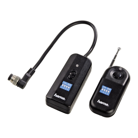
4Channel, microcomputer FMR/CTransmitter
OPERATIONS MANUAL
NOTE: PLEASE READ MANUAL COMPLETELY BEFORE OPERATION
FMA, Inc.
9607 Dr. Perry Road - Unit 109
Ijamsville, MD 21754
Sales: (800) 343-2934 -Technical: (301) 831-8980

RF FRQUENCY SELECTION
You may operate your T80 transmitter on any one of fifty RF channels at 72 MHz for airborne models and on any one of 30 RF channels at 75MHz by
selection of frequency at purchase. By F.C.C. regulations, you are not permitted to change the frequency determining element (Crystal) in your
transmitter unless you are a valid holder of an F.C.C. Second Class Operator's License.
4 OR 5 CHANNEL OPERATION
No matter how complex your model, T80 has the channel flexibility and capacity to allow you to operate any model you can build requiring from one to
five independent channels of control. If your transmitter has five channel capability, that option may be by either a switch for retract gear or by a control
knob provided for remote control of the sensitivity of the FMA COPILOT Dave(tm).
MIXING
The T80 has a program selection for mixing of aileron and elevator as used for elevons or V-tail controls.
SERVO REVERSING ON 4 CHANNELS
One can electronically change the direction of any servo using the control panel on the front of T80. A very important result obtains: Install the servos in
the most direct and functional way, to put the emphasis on the control linkage quality and reverse the servo's direction as necessary.
TRI-RATES FOR AILERON, ELEVATOR, AND RUDDER
Tri-rates gives the ability to desensitize the controls of the trainer aircraft while learning to fly without making permanent changes in linkages or available
servo travel.
TX BATTERY EVALUATION SYSTEM
Transmitter battery voltage is displayed at all times during operation. The tri-color LED display located at the upper edge of the face of the transmitter
glows green for normal operating range, transitions to yellow when the battery approaches 9V, and turns red when the danger zone is reached. If you
ever observe the display turning red, land or return your model to your presence as soon as possible. Please do check the warning light from time to
time, not after your model has crashed!
Thank you for choosing the FMA Direct T80RF, 4 channel, FM radio control transmitter. FMA Direct has been designing radio control equipment for
modelers for over 30 years. The "T80RF" uses an advanced microprocessor to control every function of the radio including:
•Rates (50%, 75%, 100%)
•Mixing (Elevon/Vtail Mix)
•Servo Reversing (All 4 Channels)
•Frequency shift selection (Positive or Negative)
The main purpose of the T80RF radio is to provide a flexible and reliable radio control system that will take the modeler into the 21st Century. The
"T80RF" meets all spectrum occupancy regulations imposed by the F.C.C.. The use of the Master Oscillator, Power Amplifier system of generating RF
allows for super narrow band, clean transmission. This permits virtually all the transmitted RF to be at the frequency of the interest instead of having
inefficient dissipation of power in unwanted harmonics. Careful shaping of the modulation pulses by a Miller Integrator ensures efficient use for the
occupied spectrum.
Please read this manual carefully before using your T80RF.
Let us know how the system works for you!
INTRODUCTION & FEA TURES
S P E C IF IC A T IO N S
SIZE: 6.75”L X 2.60”D (INCLUDING STICKS) X 6.25”H (INCLUDING HANDLE)
WEIGHT: 4 oz. (W/OUTBATTERIES)
FUNCTION: 4 CHANNEL, COMPUTER CONTROLLED, FM R/C SYSTEM
RF OUTPUT POWER: 400 Mw
FREQUENCIES: ALL LEGAL 72 MHz AND 75 MHz R/C FREQUENCIES CH 11– CH 90
MODULATION: FM/PPM (UNIVERSAL, SELECTABLE SHIFT + OR -)
POWER SYSTEM: 8 “AA” ALKALINE OR OPTIONAL ONE 8 CELL, NICD (600 Mah)
CURRENT DRAIN: 150 mA
OPERATINGPULSE WIDTH 1.0ms TO 2.0ms EACH CHANNEL (1.5ms NEUTRAL)
FEA TURES

ERGONOMICALLY DESIGNED CASE
The case of the T80 has been designed to give the maximum grip on the box while allowing your fingers freedom and flexibility to control your model
smoothly and safely.
TRIMS
Each of the four (stick controlled) channels has a trimming adjustment alongside the appropriate direction
of motion. These trims give 15 degrees of control authority in each direction to compensate for inaccuracies in the model or local conditions. They shift
the entire range of the channel motion. It is advisable to re-center the trims after each use and make the appropriate modifications to the control surfacs
using the adjustable push-rod clevis. This way the servos are centered instead of being biased off-center. It is important to know that having servos off-
center will cause non-linearity of control motion and should be avoided.
SETTING UP
Plug in the servos, receiver, battery, and switch harness that you plan to use. Check that the switches for the mixing circuits are in the OFF position
before turning on the radio. Turn on the transmitter and then the receiver. The LED battery condition display should illuminate and be green. Please be
aware that the transmitter will be radiating when you turn on. If you are operating you model at a club facility, be sure to observe the frequency control
system in effect at that location and to comply with local procedures for operating your transmitter.
STICK MODE
The stick mode can be changed from 1 to 2 as described below. The stick mode is purely a preferential choice with Mode 2 being the m9ost common
choice in the U.S. Basically, the throttle stick in the U.S. in Mode 2 is on the left and in Mode 1, it's on the right. All compensation is automatically
handled by swapping the elevator and throttle connector cables at the encoder board and the spring for the elevator need be moved to the opposite stick
by removing the back and physically changing the spring and ratchet exactly as they were on the opposite side.
MODULATION/FREQUENCY SHIFT
PPM is the baseline mode for T80. PPM allows for the use of the radio with FM receivers you may own. Your radio will work as a normal 4 or 5-channel
radio. You can use the (shift) DIP switch to select either positive or negative pulse; FMA, Futaba, Hitech, and most receivers work with negative shift
and Airtronics and JR receivers work with a positive shift. FM radio control transmitters have two possible modes of frequency shift keying (FSK). Either
the carrier is set to be nominally 1.5 KHz below the center frequency and shifts 3 KHz upward to be 1.5 KHz above the center frequency when a
modulation pulse is received at the RF deck from the encoder. This is referred to colloquially as "low-going-high" or positive shift. Most R/C transmitters
use negative shift. Two particular brands do not: JR and Airtronics/Sanwa. The latter are "high-going-low". Your T80 transmitter will accommodate
either shift so that T80 can be used with any FM/FSK receiver with PPM decoding. Please be aware that this convention occurs uniformly for the 72MHz
band. It is not always the case for 75MHz.
Select the DIP switch setting that applies to your particular receiver. Do remember to make the change if you shift from one receiver type to the other.
For this, and all functions, it is wise to check for proper operation before each flight/run of your model. While you are at it, be sure the antenna on your
transmitter and receiver are extended. More than one has flown away when the receiver antenna was left coiled up inside the model!
TRI-RATES
PREPARATION
C/10 CHARGING INSTRUCTIONS
If your transmitter has alkaline cells, they will operate for many weeks without having to be replaced. Check the LED battery display before each flight/
run and replace alkalines as soon as the display blushes red. Unlike rechargeable cells, alkaline cells do not drop precipitously as they go down in the
manner that NiCd and NiMh cells do. However, output power will reduce and range would be shortened. If your transmitter has the NiCd pack, a spe-
cific C/10 charger is provided with it for the transmitter pack and either a 500 mAh receiver pack. Transmitter and receiver NiCds require a 24-hour
charge when they are first used. After use, they will require an overnight charge (10 to 12 hours) to maintain a fully charged state. Please note that all
NiCd batteries develop a "memory" of discharge level and, if not fully discharged periodically, may refuse to discharge below this level, leading to a
false indication of capacity. It is highly recommended that you acquire an EINSTEIN battery management system for use with all your batteries, R/C or
other to ensure long-life and reliability by controlled discharge to the end of capacity, but not beyond, about once per month. (FMA Direct P/NEINX-
LDEL)
The charger supplied has two display LED's that denote that the receiver batteries and/or the transmitter's batteries are properly connected and charg-
ing.
The charging port for the transmitter is located on the left front of the case. The charger will work only when the transmitter is OFF. When the trans-
mitter is properly plugged into the charger, the appropriate LED will illuminate when the charger is on.
FAST FIELD CHARGING OF BATTERIES
Optionally, FMA Direct produces a fast field charger for T/X, R/X, and electric power packs of batteries. Even if you forgot to charge your batteries
overnight, you may charge them in 20 minutes via our peak detecting method. Several FMA Direct peak-detector fast chargers are available for this
function. You may make a selection of a fast charger that fits this and other uses from our web site at www.fmadirect.com. Read and follow the in-
structions that come with your fast charger before fast charging any battery pack.
OPERATION

Tri-rates are usually meant to desensitize stick movement for beginners from end-to-end of travel, so that over-control is minimized. Most rate settings
are used in this manner, though each person will try different uses depending on the model's needs. There is no dual rate for throttle, since and
alternate reduction of throw is not wanted in this function. A 50% dual rate is suggested on Aileron, Elevon, and Rudder for a starting point for beginning
flyers. As skill and need increases, move up to 75%, then to 100%.
SERVO REVERSING
Earlier radios had only mechanical slide switches, which became unreliable with time, and caused radio failures. Thanks to the microprocessor, this
function is now 100% electronic and extremely easy to do using highly reliable DIP switches for Aileron, Elevon, and Rudder. This function is often used
for aileron servos in reverse or when the mechanics of setting up a servo makes it easier to install on the opposite side of the servo wheel and requires,
therefore, a reverse movement.
MIXING
Models with elevons such as the FMA RAZOR flying wing and models using a V-tail for flight control require a mixer for aileron and elevator either in the
model (FMA MX80) or in the transmitter. T80 has this feature built-in and selectable. This is a 50-50 mixer. That is, it is bi-directional between the
elevator and aileron channels. For each degree of elevator motion, the aileron channel moves an equal amount and conversely. In the model, two
servos move, for example, the elevons. However, they are no longer referred to as an aileron or elevator servo, but rather, left servo/right servo. The
elevon or tail surfaces will both move upor down simultaneously for an up or down elevator command. When aileron command is given, the right servo
will move the right elevon up and the left servo will move the elevon down to produce roll. This combination then gives all the control needed for flying
the model. Always be certain you have disabled mixing when you move to a conventional model and be sure mising is engagted when you are ready to
fly an elevon model. Boat modelers may find it convenient to use this arrangement with twin motors. As stick is advanced, both motors accelerate and
as steering is applied, power to the motors provides differential steering. The rudder may be used independently on the rudder tiller. This makes the
throttle channel available for an auxiliary function. You may chose to remove the centering spring from the elevator stick and engage the ratchet to
make throttle positionable while steering is self-centering.
Table of contents
