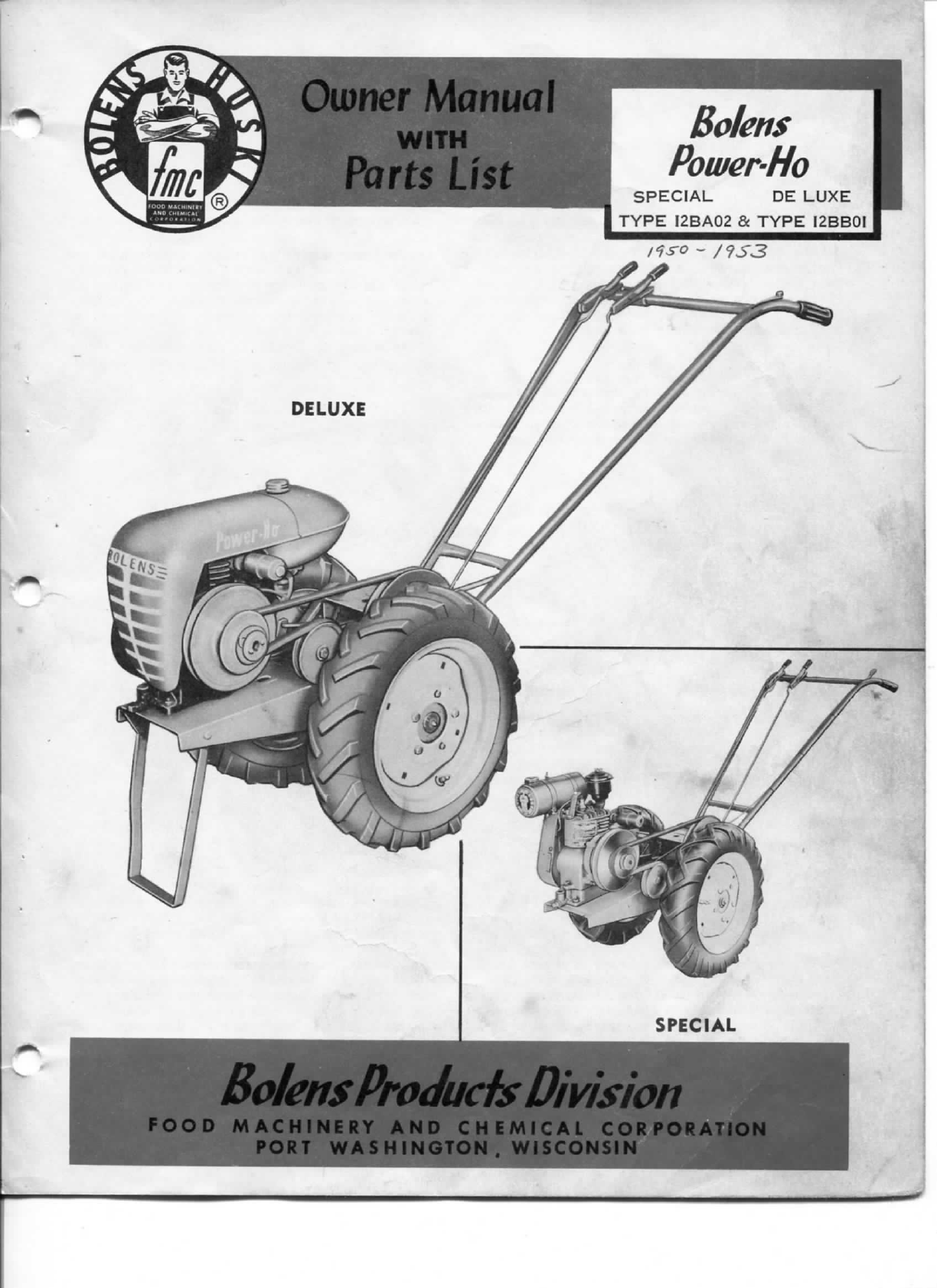
FMC Bolens Power-Ho Special User manual
Owner
Mama
WITH
Parts
List
/^s-o
- /9S3
DELUXE
Bolens Producis Division
_
FOODMACHINERYANDCHEMICALCORPORATION
PORT
WASHINGTON
.
WISCONSIN
To
The
Bolens
Owner
This
Owners
Manual
has
been
especiallyprepared
tobringtoyourattentionallinformation
needed
to
operateandmaintainyour
Powe
r
- Ho
tractorwith
maximumefficiency-Read
these
instructionscare-
fully
beforeassemblingoroperatingthetractor.
Through
propercareandoperation,asexplainedin
this
manual,youwillobtainlong,efficient
service
and
trouble
free
operationfromit.
Informationregardingoperationandmaintenanceof
thePower-Ho
engine
isnotincludedin
this
manual.
A
separate
engine
instructionmanualisincludedwith
eachtractorandshouldbeconsultedforallinfor-
mationconcerning
adjustments
andoperation.
REGISTERYOURTYPE
AND
SERIALNUMBER
Registeryourtractor
type
number,serialnumberand
engine
serialand
type
numberinthe
space
provided
below
and
always
refer tothemwhenwritingforin-
formationororderingparts.Completetheregistra-
tioncardreceivedwiththetractorandreturntothe
factory.Aname
plate
showing
type
andserialnumber
of
thetractorisattachedtotheframe.The
engine
type
andserialnumt)erisonthe
engine
nameplate.
TRACTOR
TYPE
NO.
TRACTOR
SERIAL
NO.
ENGINETYPE
NO
ENGINESERIAL
NO.
POWER-HODELUXE
TYPE
12BB101
IS
EQUIPPED
WITH
2H.P.
ENGINE
BOLENSPOWER-HOMODELS
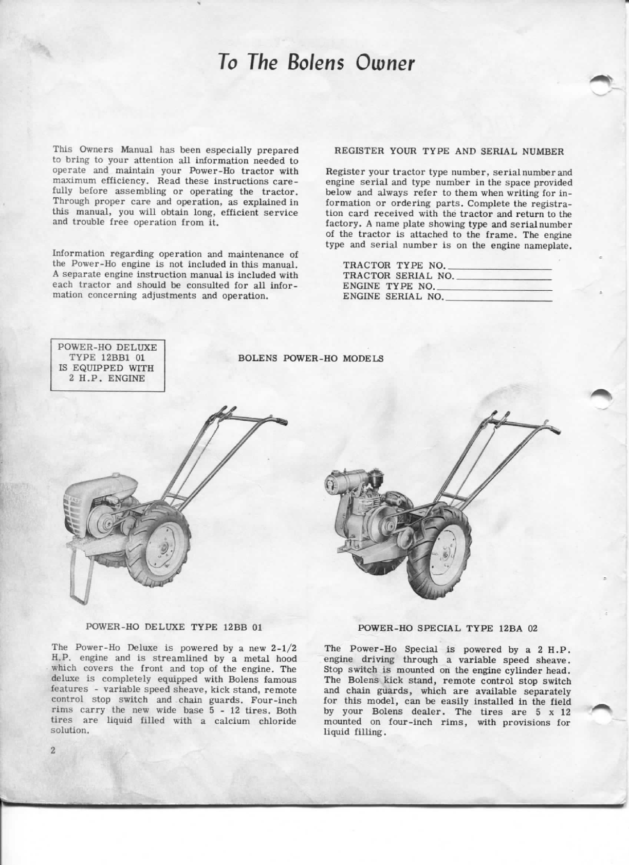
POWER-HODELUXETYPE
12BB01
POWER-HOSPECIALTYPE
12BA02
The
Power-HoDeluxeispoweredbya new2-1/2
H.P,
engine
andisstreamlinedbya metalhood
which
covers
thefrontandtopofthe
engine.
The
deluxe
is completelyequippedwithBolensfamous
features
- variable
speed
sheave,
kickstand,
remote
control
stop
switchandchainguards.
Four-inch
rimscarrythenew
wide
base
5-12tires.Both
tires
are
liquid
filledwitha calciumchloride
solution.
The
Power-HoSpecialispoweredbya 2 H.P.
engine
drivingthrougha variable
speed
sheave.
Stopswitchismountedonthe
engine
cylinder head.
The
Bolenskickstand,
remote
control
stop
switch
and
chainguards, whichareavailableseparately
for
this
model,canbe
easily
installedinthefield
byyourBolensdealer.The
tires
are5 x 12
mountedonfour-inchrims,withprovisionsfor
liquid
filling.
2

Description
Attachment
Control
Lever
Main
Idler
Control
Lever
StopSwitch
Throttle
Control
Wire
and
Shut-off
Control
Wire
Variable
DriveSheave
Figure
1.
1.
BOLENSPOWER-HO
tractorsarewalkingtype
tractorswitha ground
speed
rangeof1-1/4to
3-1/4milesperhour.A completelineofattach-
ments
areavailableforplowing,harrowing,seeding,
cultivating,lawnmowing,sicklemowing,grading,
snow
plowingandmanyotheryear-aroundopera-
tions
.
2.Thefour-cycle,single-cylinder,air-cooleden-
gine
with6 to1 gearreductiondrives thetractor
througha variablepitch
sheave
anda differential
sheave.
Speed
changes
from1-1/4to3-1/4miles-
per-hour
aremadebyvaryingthepitchofthedrive
sheave
bya simpleadjustment.Thedifferential
sheave
withratchets
allows
the
outside
wheeltoturn
fasterwhenturning.
Final
drivetothe
wheels
is
througha chainoneachwheel.
3.Allcontrolsareconvenientlylocatedonthehan-
dle.Therighthandlever
operates
maindriveidler
pulleyandthe
left
handlever
operates
front-mounted
attachments.Throttlecontrolislocatedonthe
left
handlefor
easy
accessibility.Stopswitchonthe
handleisstandardontheDeluxeandoptionalonthe
Special.
4.ThePower-Hoisequippedwithnewwide
base
tires,
size
5-12,mountedonfourinchrims.The
tiresonthedeluxearefilledwith20poundsof
calcium
chlorideforadditionaltraction.Thetires
onthespecialarenot
liquid
filledbutcanbeif
additional
tractionis desired.Twopoundsofcalcium
chloridetoonegallonofwaterwillwithstandfreez-
ing
to20°F.
5.
Front
attachments
aremountedonthefrontofthe
tractor
withBolensSnap
Hitch.
Rearmounted
attachments
areattachedbya pinintheframe.
Instructionsforinstalling
attachments
areincluded
witheachattachment.
6.A kickstandisprovidedontheDeluxemodel
whichautomatically
latches
whenkickedback.A
thumblatch
releases
thestandwhichsupportsthe
tractor
withoutattachments.
7.
TYPE
AND
SERIALNUMBER.
Thenameplate
isattachedtothetopofthetransmissionbracket,
figure1.Whenwritingforserviceinformationor
ordering
partsforyourPower-Ho,alwaysfurnish
the
TYPE
NO.and
SERIALNO.
stamped
on
this
plate.
3

Installation
StopSwitch
Throttle
Control
Clip
Spring
Clip
Throttle
Control
Wire
Shut-off
Control
Wire
Figure
2,
Transmission
BracketBolt-
Handle
Bolts
Lower
RodEnd
Idler
Control
Arm
ASSEMBLY
INSTRUCTIONS
1.Thetractor,asshipped
from
thefactory,is
crated
withthe
wheels
removedandthehandleas-
semblypackedina separatepackage.
This
handle
assemblypackageincludestwoupperidlercontrol
rodsandmainidlerlowerrodassemblywhichare
standard
equipmentonbothPower-Hotractors.
2.Installwheelassembliestotractorsothey
will
rotateindirectionindicatedbyarrowontire.Hub
boltsareshippedinaccessorybagattachedto
tractor.
3.Removethefourhandleboltsatbottomofhandle.
Position
tractorhandleandinsertbottomhandle
boltsoneachsideofframe.
Then
inserttophandle
bolts.Adjusthandletodesiredoperatingpositionand
tightenallfournuts.A handleadjustmentof7 inches
is provided
between
lowandhighhandleposition.
4.Installthemainidlercontrolassembly,which
includesthelowerspringloadedrodassembly,on
therightsideofhandleassemblyasfollows.Posi-
tion
lowerrodassemblyundertransmissionbracket
and
attachrodendtoidlercontrolarm.Insert
bottomendofmainidlercontrolrodthroughidler
rod
link
from
theinside,thenthroughcenterhole
in
springretainerandsecurewithspring
clip,
see
inset
offigure2.Usethecenterholeofspring
retainer
fortemporaryinstallation.
Then
assemble
idler
controlhandletotherightweldedbracketon
handlecrossbarwithboltsandnutsprovided.
5.Adjustidlercontrolassemblyforproperbelt
tension.
With
leverengaged,thecompressionspring
should
becompressedapproximately1/4inchto1/2
inch
forproperbelttension.Usetheproperoneof
five
holes
in springretainerforthisadjustment.
6.Insertbottomendofattachmentcontrol
rod
through
leftsideidlerrod
link
from
theinsideandsecure
withspring
clip.
Attachcontrolhandletotheleft
weldedbracketonhandlecrossbarwithnutsand
bollsprovided.
This
controlassemblyis usedfor
front
mountedattachments,suchaslawnmower
and
sicklemower.
7.Thethrottlecontrolassemblyand
stop
switchwire
havebeenproperlyassembledatthefactorythrough
thetransmissionbracket.(Stopswitchisoptionalon
Special.)
Bring
throttlecontrolwireabovelower
crossbarofhandleassemblyandattachthrottle
control
leverattop
INSIDE
positionofhandle,see
figure
2,Holes,throughthehandle,havebeen
provided
forthisinstallation.
8.
Bring
stop
switchcontrolwirewith
stop
switch
attachedoverlowercrossbarofhandleassembly
in
thesamepositionasthethrottlewire.Install
stop
switchcontroltotopendofhandlethrough
holeprovidedandattach
stop
controlwire,see
figure
2,
When
installing
stop
switchhe sureto
insertoneshoulderbushingontopandoneonbottom
of
handlesothatthemachinescrew
does
notcontact
handleandshortoutengine.
9.Threeclipsareprovidedinaccessorybagfor
holding
throttlewireandshutoffwiretogetheron
handleassembly.
4

Operation
1.
IMPORTANT:
Nooilisinthecrankcaseofthe
engine
whenshippedfromthefactory.Beforestarting
the
engine
BE
SURE
TO
FILLTHECRANKCASE
TO
THE
LEVEL
INDICATEDWITH
THE
RECOM-
MENDEDLUBRICANTSPECIFIED
IN
THEENGINE
MANUAL.
The
engine
isshippedwithoilinthe
gear
case,
however,
this
shouldbecheckedbefore
startingtobesureitisfilledtotheproperlevel.
Further
instructionspertainingtothe
engine,
its
careandlubricationarecontainedin the
engine
manual;
these
shouldbestudiedverycarefully.
2.
LUBRICATION,
Beforeoperatingyourtractor,
lubricateasfollows:
There
arefourhighpressure
grease
fittingsonthe
tractor;
oneontheidlerpulley,oneatcenterof
transmissionbracketandoneoneachwheelhub.
Lubricate
each
grease
fittingapproximatelyevery8
to10hoursofoperation.A
grease
gunis provided
withthetractor.Cleanallfittingscarefullybefore
applying
lubricant.UseMobileNo.4 (orequivalent)
and
applynewlubricantuntiloldlubricantis forced
out.Periodicallylubricateworkingpartsoftractor
withlightoiltorsmoothoperation.
3.
KICKSTAND.
Thefrontkickstandisoperated
bythumblatchatcenterofmainframedirectly
behind
the
engine.
Itautomatically
latches
tobottom
of
mainframewhenswungbackward.
4.
WHEELSETTINGS.
Twowheel
settings
areavail-
ableonthePower-Ho.Thetractorisshownin
figure1 withthe
wheels
dishedinward.This
setting
is17
inches
center-to-centuroftires.Fora wider
22-3/4
inchcenter-to-centertread,removehub
bolts
andreverse
wheels
so
they
aredishedout.
5.
TIREPRESSURE
Keeptiresinflatedto6 pounds
pressureatalltimes.Tiresfilledwithanti-freeze
calcium
chloridesolutionshouldalwaysbechecked
for
pressurewithvalveinuprightposition.
6.
OPERATION.
Start
engine
withbothidlercontrol
levers
inforwardposition.Afterthe
engine
is
run-
ning,
tostarttractor,movemaincontrolleverback.
To
stop
engine,
holddown
stop
switchuntil
engine
stops.
7.
TRACTOR
CARE.
Keepthetractor shelteredfrom
the
weather
whennotinuse.Attheendofeach
season
itisadvisabletohaveyourdealer
give
your
Power-Ho
a thoroughcheck-upforlongertractor
lifeand
better
performance.Beforestoring,
lubri-
cate
as
suggested
and
coat
any
exposed
metalparts
witha rustpreventitive.
8.
VARIABLESHEAVE.
Thevariable
sheave
pro-
vides
a ground
speed
rangeof1-1/4to3-1/4miles
perhourthroughadjustmentofpitch.Tochange
speed,liftupspringcliponadjustingnutuntil
disengagedfromchannelin
sheave
hub.Thenturn
adjustingnuttodesired
speed
position,figure3.
Four
and
one
-halfturnsofadjustingnutisthe
rangefromlowpositiontohighpositionofthe
sheave.
Thelow,or
outside
setting,
isfor
slow
forward
ground
speed
whilethehigh,orfurthest
Turn
Clockwise
To
Increase
Speed
Spring
Clip-
Adjusting
Nut
Variable
Sheave
Turn
Counterclock-
wise
toDecreaseSpeed
Figure
3
inward
setting
isforhighforwardgroundspeed.
WTien
adjustingthe
sheave
fordifferenttractor
speeds,
checkbelttensionand,if
necessary,
adjust
theidlercontrolassembly,paragraph9.
9.
DRIVEBELTADJUSTMENT.
Toinsurelongbelt
life,theidlercontrolshouldnotbesetto
cause
excessive
tensiononthebelt.Properbelttension
is obtainedwhenthecompressionspringinthespring
retaineris compressed1/4inchto1/2inch. Ad-
justmentis madebyremovingthespringcliponthe
idler
controlrod,changingthepositionofthespring
retaineratthepointofassemblytotheidlerrod
link
andcontrolrod,toanotheroneofthefive
holes
provided,
figure2.K beltadjustmentcannotbe
properly
madeby
this
procedure,
loosen
the
engine
mountingbolts,movethe
engine
forward
in
the
slotted
holes
andre-tightenbolts.Thenfinalcorrectbelt
tensioncanbemadebytheidlercontroladjustments.
10.
CHAINADJUSTMENT.
Thetransmissionbracket
is attachedtomainframewithfour
bolts
andnuts,
figures1 and2.Loosen
these
four
nuts
undermain
frame,
pull
backwardontransmissionbracketuntil
chainsare
firm
andtightennuts.Chainsshouldbe
tightenedtothepointwherethereis verylittle
slackbutcautionshouldbeusedsothatchaiRsare
nottootight.
11.
CHAINS.
Itisadvisabletorunchainsdry.
Oiling
thechains,particularlyifthetractor isbeingusedin
grittysoil,
causes
fineabrasivedirttoadheretothe
chain.
This
causes
excessive
wear.Attheendof
each
season,
removeandthoroughlywashthechains
in
kerosene;thendryand
reassemble
totractor.
12.
ENGINE.
Referto
engine
manual,
13.
TRANSMISSIONSHAFT.
Thisshaftcontains
hardenedportionswhichareatdifferentpositions
from
theend.Theseportionscannotbereadily
identifiedasboth
ends
arefinishedoffexactlyalike
witha Woodruffkeywayanda snap
ring
groove.
However,a
spot
drill
isontherighthandendof
this
shaftandwheneverchanging
this
partitis
necessary
that
this
spot
drilledendbeassembledontheright
hand
side
whenviewingthetractorfromtherear.
14.
JACKSHAFTSHEAVE.
Differentialactionwheel
ratchetsareattacheddirectlytothejackshaft
sheave.
The
unitis packedwith
grease
atthefactoryandthe
ratchetsshouldberemoved
once
a yearforrepack-
ing
witha goodfiber
grease.
Thisratchet
sheave
allows
smoothturningand
easy
operationofthe
tractor.

6

IMPORTANT
ORDERING
INSTRUCTIONS
InappointingBolens
agencies
consideration
has
been
given
to
theirability
to
provideprompt
and
efficientservice.
We
recommend
that
yourlocal
dealer
be
contacted
for
your
service
requirements.
He
wiU
furnishcorrectpartsfrom
his
stock
or
order
them
foryouif
necessary.
To
insure
getting
correctmaterialswithoutdelay
please
supply
the
followinginformation.
Please
print
to
avoiderrors.
1.
The
type
number
ofthe
Power-Hotractor
and
serialnumberstamped
onthe
nameplate.
2.
Whenordering
engine
parts
giveengine
serial
and
type
number
as
stamped
onengine
plate.
3.Quantity,partnumber,
and
description
of
each
part
wanted.
4.
Advise
asto
whether
partsshould
be
shipped
by
mail,
expressor
freight.
(All
repairorders
are
shipped
F.O.B.
factory.)
5.
Name,shippingaddress
and
mailaddress.
This
parts
list
covers
both
models
12BAand12BB.
Wheredifferences
between
models
occur
themodel
ofthe
tractor
on
which
the
part
is
used
follows
name
of
part
in
parenthesis.
Ref.
No.
No.
Part
No.
Description
Req*d
1
181030
Wheel
- 3"*
2
1701393
Wheel
- 4"**
2
2
101085
Hub
Bolt
6
3
1104954
GreaseFitting
3
4
121896
Retainer
Ring
2
5
121895
Thrust
Washer,
7/8
2
6
308932
Spacer 2
7
1185007
Bearing
4
8
990578
Hub
&
SprocketAssy
(lessbrgs)2
9
1185013
Link
2
10
180124
Drive
Chain
2
11 119469
Spindle 2
12
1185050
KnurledSetScrew,
3/8-16x3/8
2
13
990601
Kick
Stand(12BB)
1
14 990599
Frame
1
15 149899
Latch
Spring(12BB)
1
16
308761
Stand
Latch
(12BB)
1
17
Woodruff
Key,
5/32x 5/8
2
18
211046
Drive
Sprocket
1
19
1185010
Bearing
2
20 308747
IdlerRod
Link
2
21
1700984
Clip
2
22
990581
TransmissionBracket
1
23
1110086
GreaseFitting,
45*^ 1
24
990586
IdlerPulley
1
25
190138
Pulley
Sleeve 1
26
1107372
Flat
Washer,
1/2 1
27
129042
IdlerPulleyBolt
1
28
119533
TransmissionShaft
1
29
990583
InnerRatchetw/sprocket
— 1
30 990497
Sheave
1
31 149897
Pawl
Spring 2
32 308737
Pawl
2
33
990584
Outer
Ratchet
1
34 121897
Retainer
Ring
2
35
1700880
Thrust
Washer
As
Req'd.
36
990618
Chain
Guard
L.H.
(12BB)
1
37
180173
Chain
1
38
310814
Pin
1
39
1700774
Spring**
1
40
Machine
Screw,
10-32x 3/8**
2
41 1700779
SpecialWasher**
1
42
1700773
SpecialNut**
1
43
1702386
Adjusting
Sheave**
1
44 1104335
Key,
3/16x3/16x2** 1
45
1702384
Variable
Sheave**
1
46
SetScrew,
3/8-16
x 1/4**
2
47 17
0078
0
Variable
Sheave
Assy**(Incl.
39
thru
46) 1
Ref.
No.
No.
Part
No.
Description
Req'd.
48
1700398
Drive
Sheave*
1
49
Sq.
Key,3/16x 3/16x 1* 1
50
310830
Lower
Control
Rod
1
51
149896
Spring
1
52 1107369
Washer,
5/16 1
53
308788
Spring
Retainer
1
54 1700989
Lower
Control
Assy(Incl.
50
thru
53) 1
55 135037
Spring
Clip
2
56
180886
Rubber
Handle
Grip
2
57 310827
Idler
Control
Rod 2
58
308878
•
Throwout
Lever 2
59 308879.
Throwout
Clamp 2
60 130147
Bearing
Pin
2
61
990625
Lever
Assy
{Incl.
55
thru
60)
2
62
290568
Throttle
Lever
1
63 1701079
Throttle
Wire,
66" 1
64
1701080
Throttle
Casing,
63" 1
65
1700806
Throttle
Assy(Incl.
62,63,64)
1
66
180885
Handle
Grip
67
1700213
Ground
Switchfl2BB)
1
68
Mach
Screw,
8-32x 1-1/2(12BB)1
69
1701051
ShoulderBushing(12BB)
70
1701361
Ground
SwitchAssy(12BB)(Incl.
67,
68,
69.
washers
&
nuts) 1
71
1701288
Ground
Wire
(12BB)
1
72
149925
Cable
Clip
73 1700799
Wire
Clip
(12BB)
74
990595
Welded
Handle(Only)
1
75
1701520
Gasoline
Tank
(12BB)
1
76 1701529
Tank
Support(12BB)
1
77
1701528
Hood
(12BB)
1
78
1701522
Grille
(12BB)
See
Note
1 1
78
1703010
Grille
(12BB)
See
Note
2 1
79 1701525
Grille
Mounting
Clip
(12BB)
1
80
1700141
Fuel
Strainer(12BB)
1
81 1701575
Connector(12BB)
1
82 66489
Gasoline
Line
(12BB)
1
83
1701513
BeltStop
1
84
1108566
Belt,
57" 1
85
990611
Chain
Guard,
R.H.(12BB)
1
86
1700321
Spacer(12BB)
See
Note
1 1
87
1701531
Spacer(12BB)
See
Note
1 1
88
1701530
Spacer(12BB)
See
Note
1 1
89
1103201J
SpecialScrew,
5/16-18
x 1-3/^
(12BB)
See
Note
1
90
1701536
Brace
(12BB)
1
91 1701675
Nipple
(12BB)
1
92 1701997
Seal(12BB)
I
NOTE:
All
bolts,
nuts
and
washers
are
standard
ImplementDealer.
*
Used
on12BAupto
Serial
No.
A18710
**
Used
on12BA
afterSerial
No.
A18710
and
all12BB
Models
can
be
obtainedfromyour
Local
Hardware
or
1-
Used
on
12BBwith
engine
type
No.
702814
sizes
and
NOTE
NOTE
2 -
Used
on
12BBwith
engine
type
No.107829
NATIONWIDE
SERVICE....
GENUINE
FACTORY
REPAIR
PARTS
The
BolensDivision
of
FoodMachinery
Cor-
poration
has
established
a
nationwidereputa-
tion
for
qualityproducts.Thisreputation,
gainedthroughadvancedengineering
and
effi-
cientmanufacturing
methods
is
important
to
rememberwhenbuyingreplacementparts.
Genuine
Bolenspartsassure
the
continued
highperformance originallybuiltintoyour
equipment.Bolensdealers
are
appointed
on
theirabilitytoprovidepromptefficientservice,
and
are
backed
bythe
Bolensserviceorgani-
zation.Whenreplacingpartsconsultyour
nearest
Bolensdealer
for
GENUINEBOLENS
SERVICE
PARTS
When
buying
new
equipment,remember
the
protectiveserviceofferedthrough
the
Bolens
dealer
in
yourcommunity.
PIONEERMANUFACTURERS
OF
GARDENTRACTORS
ANDEQUIPMENT
FOODM A C H I
Form
No.550338-4
PORT
I
R
Y ANDCHE
WASHINGTON,
IC A L
CORPORATION
WISCONSIN
Ken
Cook Milwaukee
LHtw
U.S.A.
This manual suits for next models
3
Table of contents


