manuals.online logo
Brands
  1. Home
  2. •
  3. Brands
  4. •
  5. RHINO
  6. •
  7. Tractor
  8. •
  9. RHINO RHINO 2409 User manual

RHINO RHINO 2409 User manual

Other manuals for RHINO 2409

5

Other RHINO Tractor manuals

RHINO KUBOTA GRAND-L30 Series User manual

RHINO

RHINO KUBOTA GRAND-L30 Series User manual

RHINO 95 BACKHOE User manual

RHINO

RHINO 95 BACKHOE User manual

RHINO 2347 QT User manual

RHINO

RHINO 2347 QT User manual

Popular Tractor manuals by other brands

Capital Automotive Equipment CAEL-245 manual

Capital Automotive Equipment

Capital Automotive Equipment CAEL-245 manual

Kubota MX5200 Operator's manual

Kubota

Kubota MX5200 Operator's manual

Verts Loisirs VLB12597 instruction manual

Verts Loisirs

Verts Loisirs VLB12597 instruction manual

satoh BULL S-630 Instruction book

satoh

satoh BULL S-630 Instruction book

Yard-Man Series 834 owner's manual

Yard-Man

Yard-Man Series 834 owner's manual

Cub Cadet 19A30024100 installation manual

Cub Cadet

Cub Cadet 19A30024100 installation manual

Ariens 936051 Operator's manual

Ariens

Ariens 936051 Operator's manual

MacDon M150 Assembly instructions

MacDon

MacDon M150 Assembly instructions

Toro 03200 Reelmaster 3100-D Operator's manual

Toro

Toro 03200 Reelmaster 3100-D Operator's manual

MASSEY FERGUSON 5400 Series Service manual

MASSEY FERGUSON

MASSEY FERGUSON 5400 Series Service manual

Belarus 3522.5 Operator's manual

Belarus

Belarus 3522.5 Operator's manual

CARRARO Vigneto Operator's manual

CARRARO

CARRARO Vigneto Operator's manual

Cub Cadet 3208 Operator's manual

Cub Cadet

Cub Cadet 3208 Operator's manual

GREMO 1250F Workshop manual

GREMO

GREMO 1250F Workshop manual

HATTAT A90 Service manual

HATTAT

HATTAT A90 Service manual

Kubota WSM STV32 Workshop manual

Kubota

Kubota WSM STV32 Workshop manual

Kubota M108DC Operator's manual

Kubota

Kubota M108DC Operator's manual

AL-KO Heritage RS 14/82 Instruction book

AL-KO

AL-KO Heritage RS 14/82 Instruction book

manuals.online logo
manuals.online logoBrands
  • About & Mission
  • Contact us
  • Privacy Policy
  • Terms and Conditions

Copyright 2025 Manuals.Online. All Rights Reserved.

F-3978 1 of 4 7-2-2004
2-7414
MOUNT KIT
2409 LOADER
MASSEY FERGUSON TRACTORS
ASSEMBLY MANUAL
Keep With Operator's Manual
Mounting brackets can be installed using tools ordinarily
available. Shut off tractor engine and engage tractor
brakes during installation.
After loader is installed, check to be sure front tires clear
loader and mounting brackets in all possible positions.
NOTE: Leave all attaching hardware loose until mount-
ing brackets are completely assembled to facilitate as-
sembly and proper alignment. Tighten all hardware to
torque specifications in loader operators manual.
INSTALLING MOUNTING BRACKETS (Figure 1)
1. Remove bolts securing tractor front weight bracket to
tractor front casting. Refasten weight bracket with
front mounting bracket (1) mounted over front weight
bracket using 5/8 x 2” cap screws (15) and 5/8” lock
washers (18).
2. Install left midmounting bracket (4) to tractor trans-
mission casting using 3/4” spacer (5), 5/8” flat
washer (19), 5/8” lock washer (18) and 5/8 x 2-1/2”
cap screw (8) in upper rear hole and 5/8” flat washer
(19), 5/8” lock washer (18) and 5/8 x 1-1/2” cap screw
(9) in upper front hole. Fasten lower holes in left
midmounting bracket using .69” spacers (6), 5/8 lock
washers (18) and 5/8 x 2-1/4” cap screws (16).
3. Install right midmounting bracket (3) to tractor cast-
ing using 3/4” spacer (5), 5/8” flat washer (19), 5/8”
lock washer (18) and 5/8 x 2-3/4” cap screw (14) in
upper rear hole and 5/8” flat washer (19), 5/8” lock
washer (18) and 5/8 x 1-3/4” cap screw (17) in upper
front hole. Fasten lower holes in right midmounting
bracket using 2.69” spacers (7), 5/8” lock washers
(18) and 5/8 x 4-1/4” cap screws (21).
4. Remove inspection cover plate on underside of
clutch housing.
5. Fasten cross tie (2) to right and left mid mounting
brackets (3 & 4) using 5/8 x 2” cap screws (15) and
5/8” lock nuts (20).
6. Fasten cross tie to bottom of tractor using 5/8” flat
washers (19), 5/8” lock washers (18) and 5/8 x 1-3/4”
cap screws (17).
MODEL 2WD 4WD LESS CAB WITH CAB
MF431 X X
7-2-2004 2 of 4 F-3978
2-7414
PARTS LIST - MOUNTING KIT
ITEM PART NO. DESCRIPTION QTY.
1 52371 BRACKET, Front Mounting 1
2 51864 CROSS TIE 1
3 51861 BRACKET, Midmounting, Right 1
4 51868 BRACKET, Midmounting, Left 1
5 42787-1 SPACER TUBE .75" 2
6 42787-7 SPACER TUBE .69" 2
7 42787-6 SPACER TUBE 2.69 2
8 41838-64 SCREW, Cap, 5/8-11 x 2-1/2 1
9 41838-29 SCREW, Cap, 5/8-11 x 1-1/2 1
10 41838-7 SCREW, Cap, 3/4-10 x 2-1/2 4
11 41840-8 NUT, Lock, 3/4-10 4
12 52374 YOKE 1
13 39240 DECAL, Do not tow ... 2
14 41838-79 SCREW, Cap, 5/8-11 x 2-3/4 1
15 41838-27 SCREW, Cap, 5/8-11 x 2 10
16 41838-14 SCREW, Cap, 5/8-11 x 2-1/4 2
17 41838-32 SCREW, Cap, 5/8-11 x 1-3/4 5
18 41837-7 WASHER, Lock, 5/8 18
19 42502-12 WASHER, Flat, 5/8 8
20 41840-7 NUT, Lock, 5/8-11 4
21 41838-78 SCREW, Cap, 5/8-11 x 4-1/4 2
INSTALLING LOADER TO MOUNTING
BRACKETS
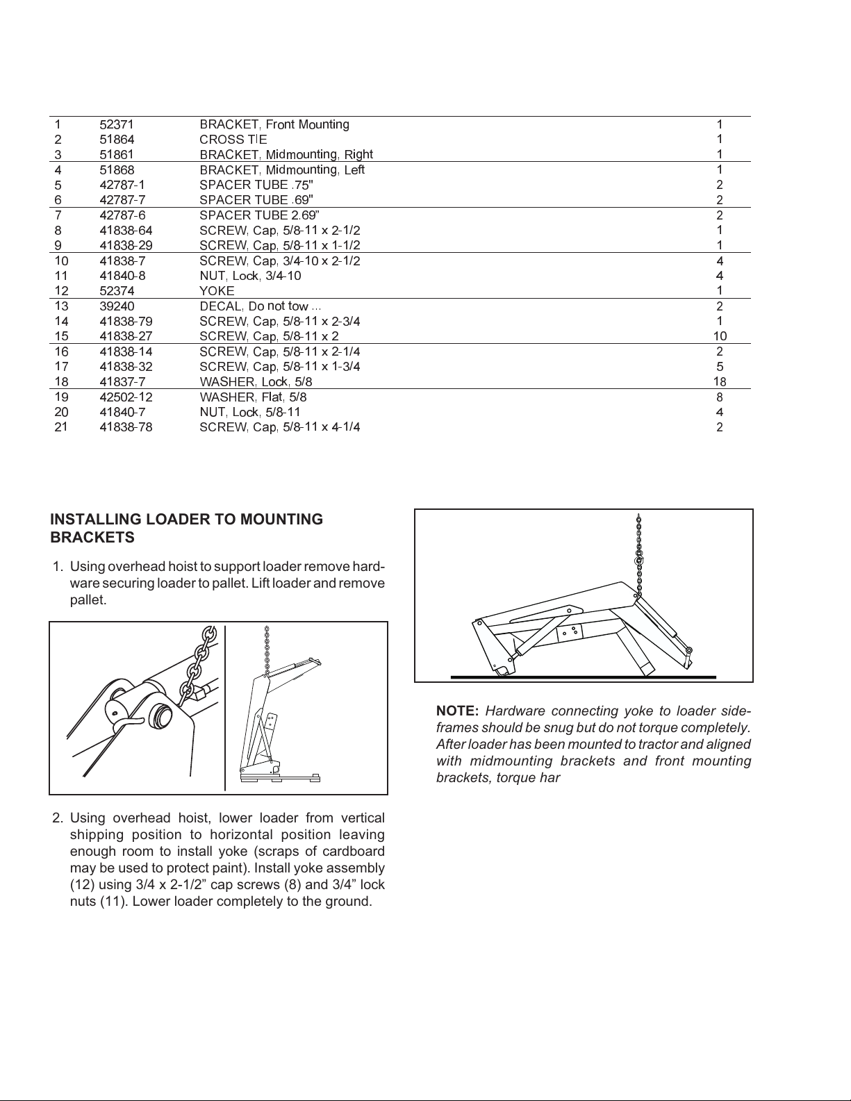
1. Using overhead hoist to support loader remove hard-
ware securing loader to pallet. Lift loader and remove
pallet.
2. Using overhead hoist, lower loader from vertical
shipping position to horizontal position leaving
enough room to install yoke (scraps of cardboard
may be used to protect paint). Install yoke assembly
(12) using 3/4 x 2-1/2” cap screws (8) and 3/4” lock
nuts (11). Lower loader completely to the ground.
NOTE: Hardware connecting yoke to loader side-
frames should be snug but do not torque completely.
After loader has been mounted to tractor and aligned
with midmounting brackets and front mounting
brackets, torque hardware to 239-262 ft. lb.
3. Install hose or valve kit to tractor and loader. Refer to
assembly manual provided for installation instruc-
F-3978 3 of 4 7-2-2004
2-7414
10
11 13
21
18
17
14
18
19
3
20
5
7
15
19
18
17
15 18
19
8
9
18
19
16
18
5
6
4
1
12
2
Figure 1
Mount Kit Assembly
7-2-2004 4 of 4 F-3978
2-7414
INSTALLING LOADER TO MOUNTING
BRACKETS (Continued)
4. Reposition overhead hoist by looping nylon strap
around yoke near loader side frames at balance
point of loader.
5. Using overhead hoist, raise loader until side frame
uprights will clear front tires. Remove locknut and
washer from loader hinge and swing each hinge
open.
6. Position loader so hinges hook over mid mounting
tubes and yoke tube fits inside front mounting
bracket.
7. Clamp hinges to midmounting tubes with 3/4”flat
washers and 3/4”flex-lock nuts (supplied with
loader).
IMPORTANT: Be sure to use flex-lock nuts to clamp
hinge. Tighten flex-lock nuts against hinge securely,
but not to more than 125 ft.-lb. torque.
8. Adjust front wheel tread settings or steering stops, if
necessary to prevent interference between tires and
loader. Refer to tractor operator's manual for adjust-
ment procedures.
INSTALLING BUCKET
Refer to instruction sheet for instructions on installing
bucket.
INSTALLING BUCKET LEVEL INDICATOR
1. Attach indicator guide tube to cylinder pin. Guide
tube is positioned to outside of boom.
2. Slide bucket level indicator rod through guide tube.
Attach other end of rod with 1/8 x 1”cotter pins and
3/8”flat washers.
3. Locate tractor and loader on level surface. With bot-
tom of bucket resting on surface, cut off excess rod
flush with end of guide tube or paint exposed rod a
contrasting color.
Balance point
of loader
Hinge open
Level Indicator for
Pin-On or Quick-Attach
Buckets or Attachments
Indicator
Guide
Tube Loader Right
Boom Arm
Cotter Pins
Flat Washers
Indicato
r
Rod
INSTALLATION INSTRUCTIONS