FMUSER INTERNATIONAL GROUP INC. 广州市汉婷生物技术开发有限公司
2/ 57
Directory
Chapter 1 Product Outline...............................................................................3
1.1 Outlines .................................................................................................................3
1.2 Features.................................................................................................................4
1.3 Specifications.......................................................................................................5
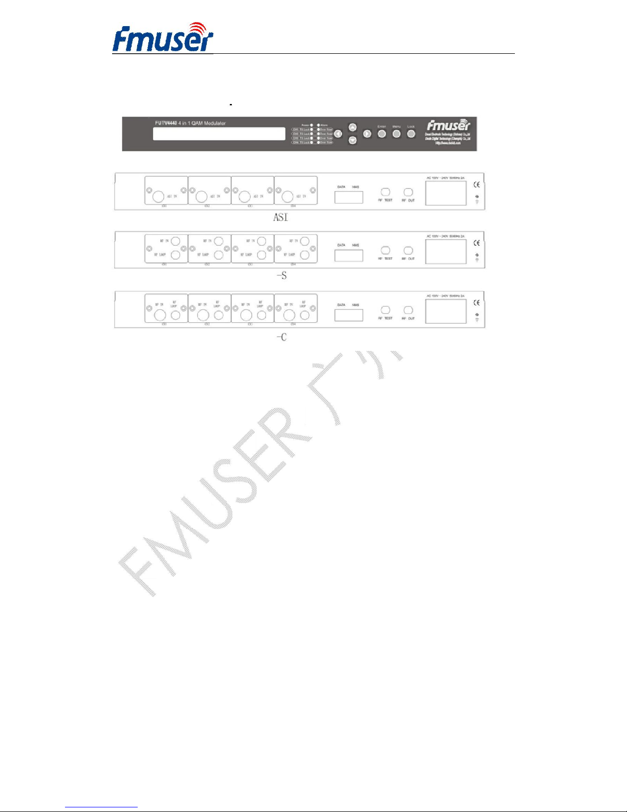
2.1 Front panel............................................................................................................6
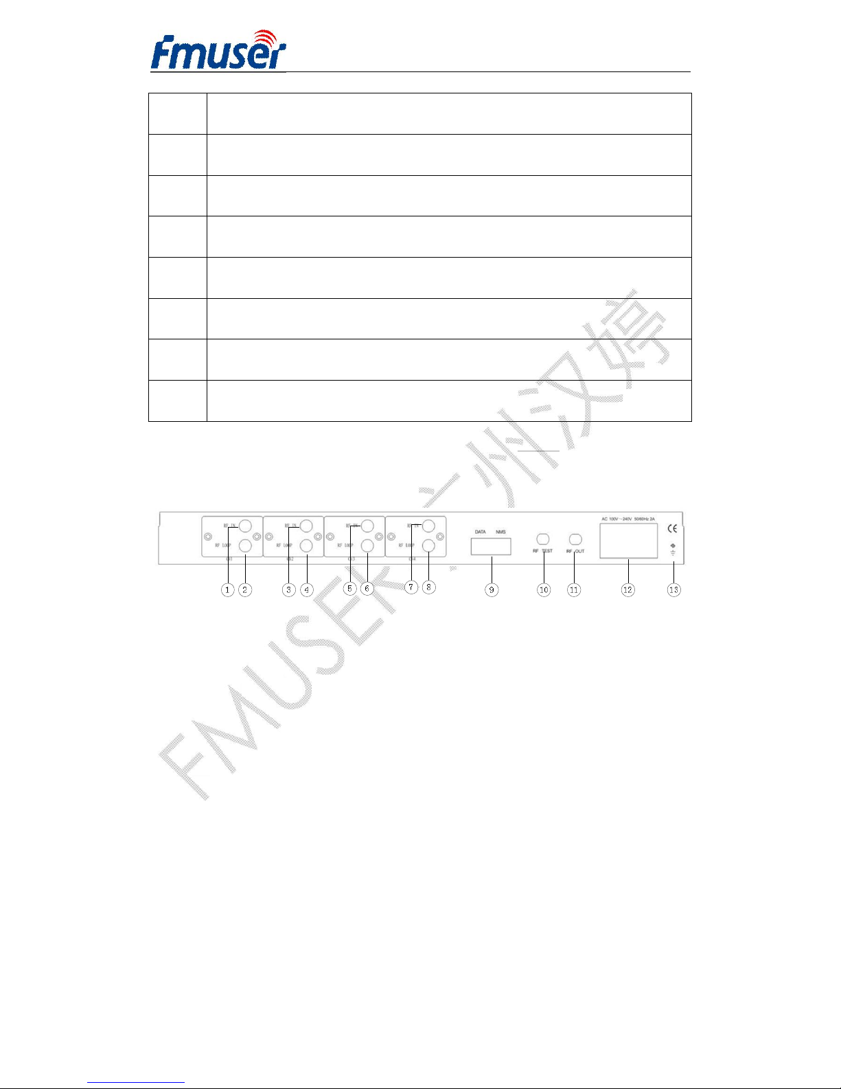
2.2 Rear Panel: (The 4-in-1 QAM modulator can take various RF inputs of
DVB-S/DVB-C/DVB-S2 signals by installing the relevant build-in tuners or ASI
input optional.) ............................................................................................................6
Chapter 3 Installation Guide............................................................................9
3.1 Acquisition check.................................................................................................9
3.2 Installation Preparation .......................................................................................9
Chapter 4 Operation.......................................................................................14
4.1 Operation.............................................................................................................14
4.2 Main Interface .....................................................................................................14
Chapter 5 NMS Setting...................................................................................32
5.1 Installation...........................................................................................................32
5.2 Software Operation ............................................................................................32
5.3 FUTV4440B 4in1 QAM Modulator Operation...................................................39
Chapter 6 Troubleshooting ...........................................................................56
Chapter 7 Packing List...................................................................................57