PROception proMOD1 User manual

Page 1Page 4
UHF A/V modulator
PD2011-9005-03
INSTALLATION AND OPERATION INSTRUCTIONS
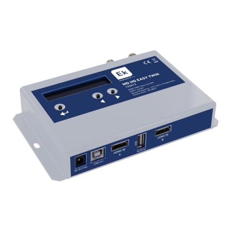
The proMOD1 is a general purpose A/V modulator for use where a UHF TV signal
needs to be generated from the output of e uipment which does not have an internal
modulator.
Features
nStandard A/V inputs on SCART socket (phono adapter supplied).
nUK (System I ) double-sideband modulated output.
nUHF output channel selectable in range E21 to E69 (setting automatically restored
on power-up).
nVHF-UHF loop-through input.
nBuilt-in mains power supply.
Applications
nCCTV security cameras, DVD players, camcorders, games, etc.
Location
The modulator can be located in any convenient position and does not re uire fixing.
Clearance of at least 50 mm should be allowed above and around the unit for
ventilation. Avoid positioning the modulator on top of a stack of other e uipment as
this may result in an excessive ambient temperature.
Do not leave the modulator resting on a carpet or install it where it may
become smothered with curtains or other soft furnishing fabrics. When
installing the modulator in a roof space ensure that it will not come into contact
with thermal insulation material.
RF signal connections
To preserve RF screening integrity the signal connections to the modulator should be
made using good uality coaxial cable and connectors (IEC type). This is particularly
important in a system carrying digital terrestrial TV (DTT) to minimise the ingress of
impulsive electrical interference from home appliances.
The use of crimp connectors, used in accordance with the manufacturers instructions
will give the best results. The importance of achieving sound braid connections cannot
be over-stressed. The use of cable benchmarked under the CAI scheme is
recommended.
Performance data given are typical unless otherwise stated. Proception Limited reserves the right to change
product designs and specifications without prior notice.
Safety Instructions
OVERHEATING
The recommen e ventilation clearances an other precautions given in the relevant section
of this instruction leaflet shoul be observe to prevent overheating. No unit shoul be fixe
where it is likely to become smothere by soft furnishing fabrics such as curtains, or by thermal
insulation material in a roof space or buil ing voi . Mains powere equipment shoul not be
left resting on a carpet.
WATER AND FIRE RISKS
The appliance is not waterproof. It is inten e for in oor use only an must not be fixe where
it coul be expose to ripping or splashing water. Objects containing liqui s shoul not be
place on or near the appliance.
To prevent risk of fire, no object with a nake flame shoul be place on or near the appliance,
or its associate wiring.
MAINS PLUG
The appliance is supplie with a stan ar fuse plug fitte . If this is unsuitable, refer to the
instructions below. If you nee to change the fuse in the fitte plug, a 3 Amp fuse to BS 1362
carrying the ASTA or BSI approval mark must be use . Always replace the plastic fuse carrier
when renewing the fuse.
CHANGING THE PLUG
If the fitte mains plug is not suitable for the socket-outlets in use, it shoul be cut off an a
new plug fitte .
Wiring the New Plug: Instructions supplie with the new plug shoul be followe . The brown
wire must be connecte to the live (L) terminal of the plug an the blue wire to the neutral (N)
terminal. Neither wire shoul be connecte to the earth (E) terminal of a 3-pin plug (the
appliance oes not require an earth connection). Ensure that the cor grip in the plug is correctly
use an clamps the sheath of the cor firmly.
Fuse Rating: If the new plug is a fuse type, the fuse fitte shoul be rate at not more than 3
Amp.
Caution: The ol plug shoul be estroye imme iately since it woul be angerous if plugge
into a live socket.
proMOD1
2-Year Guarantee
This guarantee covers failure of your PROception pro uct resulting from manufacturing efect
within a perio of 2 years from the ate of supply to the en -user. This guarantee oes not
cover amage to the pro uct cause by abuse, tampering, efective installation or natural
causes such as lightning ischarge. Repair or attempte repair, other than by the manufacturer,
will ren er this guarantee voi . This guarantee oes not affect a consumers statutory rights.
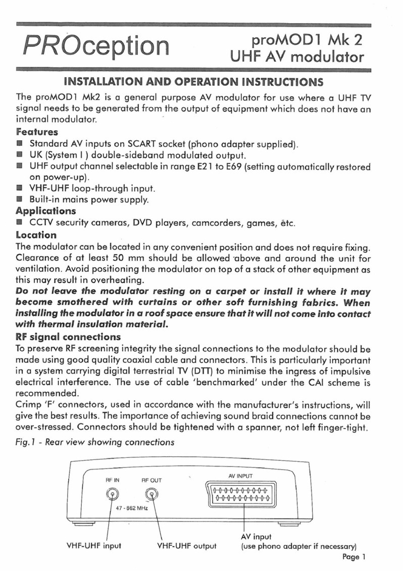
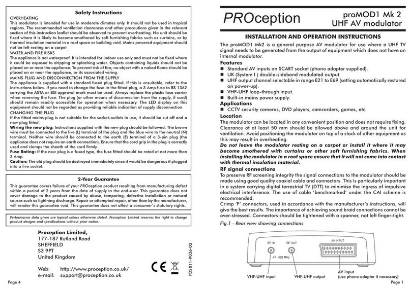
Fig.1 - Rear view showing connections
VHF-UHF input
$17,1 5)287
$
9,1387
VHF-UHF output
A/V input
(use phono a apter if necessary)
Proception Limited,
177-187 Rutland Road
SHEFFIELD
S3 9PT
United Kingdom
eb: http://www.proception.co.uk/
e-mail: [email protected]
PROception

Page 3Page 2
Mains supply and safety notes
The modulator is supplied with a fitted mains plug and may be plugged directly
into a 13 A (BS 1363) soc et outlet. If soc et outlets of a different type are in use,
please refer to the safety instructions on page 4.
Alternatively the plug may be cut off and the modulator wired into a fused
connection unit, fitted with an approved 3 A fuse to BS 1362. This method of
connection is recommended for permanent distribution system applications, since
it reduces the ris of tampering and accidental disconnection.
If the modulator is not connected to the mains using the fused plug supplied, or
a fused connection unit, it must be protected by means of a fuse or MCB at the
final distribution board of rating not exceeding 6 A. An isolating switch should be
provided to allow the unit to be disconnected from the supply when necessary.
Any fixed wiring installed to supply power to this modulator should comply with
BS 7671 (IEE wiring regulations, 16th Edition).
The proMOD1 modulator is of Class 2 construction and does not require a
protective earth connection. This does not obviate the need to provide a circuit
protective (earth) conductor in the supply wiring, as required by BS 7671.
Distribution systems supplying signals to more than one household should comply
with the safety requirements of BS EN 50083-1. This effectively requires the
system to be earth bonded. (The use of isolated outlet plates is no longer
recommended since they compromise screening integrity and allow ingress of
interference.)
Setting the output channel number
The channel setting buttons on the front of the unit are normally loc ed to protect
against accidental change or tampering. To change the output channel setting
proceed as follows:
1. Press and hold both buttons together for about two seconds. The channel no.
display will start to flash.
2. While the display is flashing, adjust the channel no. as required using the s
or t button.
3. When the display stops flashing (about two seconds after the last button press)
the new channel setting is stored in the non-volatile memory.
4. Repeat from Step 1 if necessary, to try a different channel, or if the time-out
occurred too soon.
If the output channel is changed after installation, all TV receivers which are
using the modulators output will need to have the appropriate channel setting
retuned.
Notes on channel selection
Choice of an appropriate modulator channel setting is important to avoid
interference problems.
nThe modulator output should not be set on the same channel as any off-air
analogue or digital signal carried on the system. Using a channel which coincides
with an off-air DTT signal is a common cause of a noisy loo ing modulator
picture.
nAlso avoid adjacent channels (N±1 relationship).
nAvoid any combination which results in signals spaced 5 channels apart (N±5
relationship).
nThe old avoid N±9 rule can usually be ignored, due to the improved image
rejection of modern TVs.
nAny other modulators in the same system (in VCRs, etc.) are subject to the
same rules, which also apply between modulators.
nTo chec for interference caused by the modulator, switch off the modulator at
the front panel.
nTo chec for interference caused by an off-air signal to the modulator, unplug
or switch off the antenna feed.
Information on UK TV transmitter channel numbers can be found at the following
Web URL:
http://www.bbc.co.u /reception/tv_transmitters/
(Information subject to change)
metsysVT)1eton()074.TB.ceRR-UTI(ImetsyS
epytmurtcepsnoitaludo dnabedis-elbuod
lennahcFHUtuptuO )yromemelit
alov-nonniderots,lenaptnorfmorftes(96E..12E
levellangistuptuO).cnyskaep,lacipyt(VµBd47
htdiwdnabhguorht-
poolFRzH268..45
niaghguorht-poolFRBd0
leveltupnioediV57lanretni(p-pV1 Ω)noitanimret
leveltupnioiduA gnitalud
omzHk1(noitaivedkaepzHk02±rofenisSRVm056
)2eton()ycneuqerf
tnemeriuqerrewoP 3631SBotgulpsniamdettifhtiw
deilppus,AV5<tazH05CAV032
1. Tolerances given in the ITU-R Recommendation are not applicable.
2. The L & R inp ts are added to provide a mono signal for mod lation.
Technical data
SCART connector pin connections (NC = no internal connection to pin.)
Fig.2 SCART connector
pin numbers
(view towards socket)
1
19
20
2
.onnipnoitcennoc
1CN
2nioiduaR
3CN
4)oidua(dnuorG
5dnuorG
6nioiduaL
7CN
8CN
9dnuorG
01CN
.onnipnoitcennoc
11CN
21CN
31dnuorG
41dnuorG
51CN
61CN
71)oediv(dnuorG
81dnuorG
91CN
02)SBVC(nioediV
12)llehs(dnuorG
Other PROception Modulator manuals
