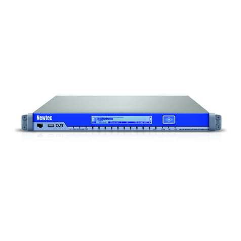
Fracarro SIG7412 T MPEG2 User manual

SIG7412 T MPEG2
Encoder Modulator User Manual
Manuale d’uso Encoder

pag2
About This Manual
Intended Audience
This user manual has been written to help people who have to use, to integrate and to install
the product. Some chapters require some prerequisite knowledge in electronics and
especially in broadcast technologies and standards.
Disclaimer
No part of this document may be reproduced in any form without the written permission of
the copyright owner.
The contents of this document are subject to revision without notice due to continued
progress in methodology, design and manufacturing. Fracarro shall have no liability for any
error or damage of any kind resulting from the use of this document.
Copy Warning
This document includes some confidential information. Its usage is limited to the owners
of the product that it is relevant to. It cannot be copied, modified, or translated in another
language without prior written authorization.

pag3
Contents
Chapter 1 Introduction...................................................................................4
1.1 Product Overview.................................................................................................................................................4
1.2 Key Features.........................................................................................................................................................4
1.3 Specifications........................................................................................................................................................5
1.4 Principle Chart......................................................................................................................................................6
1.5 Appearance and Description................................................................................................................................7
Chapter 2 Installation Guide.........................................................................8
2.1 Safety Warning.....................................................................................................................................................8
2.2 Installation warnings.............................................................................................................................................8
2.3 General warnings..................................................................................................................................................9
2.4 CONFORMITY TO EUROPEAN LAWS...........................................................................................................9
Chapter 3 WEB NMS Operation..................................................................10
3.1 Encoder login......................................................................................................................................................10
3.2 Encoder Modulator Operation............................................................................................................................11
Chapter 4 Troubleshooting..........................................................................27
Chapter 5 Packing List................................................................................28

pag4
Chapter 1 Introduction
1.1 Product Overview
SIG7412 T MPEG2 12 in 1 encoder modulator is Fracarro’s newest devices which integrate MPEG2
encoding, multiplexing, and DVB-T modulation.
It supports 12 CVBS input. It also support DVB-T RF out with 4 adjacent carries
(50MHz~960MHz), and support Data1 (GE) output port to support 4 MPTS
out. This full function device makes it ideal for small CATV head end system,
and it’s a smart choice for hotel TV system, entertainment system in Hospitality environments.
1.2 Key Features
• 12 A/V inputs with MPEG2 encoding.
• MPEG1 Layer II, AC3(2.0) Audio encoding and support audio gain adjustment
• 4 groups multiplexing and 4 DVBT RF carriers out
• Support IP (MPTS only, DATA1 port only) output over UDP and RTP
• Support “Null PKT Filter” function
• Excellent RF output performance index, MER≥40dB
• Support PID remapping
• Support accurate PCR adjusting
• Support PSI/SI editing and inserting
• Control via web management, and easy updates via web

pag5
1.3 Specifications
Input
12 CVBS inputs , RCA interface ,
Video
Resolution
720×480_60i, 544×480_60i, 352×480_60i
352×120_60i,320×120_60i,176×120_60i, 176×120_60i
720×576_50i,704×576_50i,640×576_50i, 352×288_50i
320×288_50i, 176×288_50i, 176×144_50i
Encoding MPEG2
Bitrate 0.5Mbps~8Mbps each channel
Rate Control CBR
GOP Structure IBBP
Advanced
Pretreatment Deinterlacing, noise reduction
Audio
Encoding MPEG1 Layer 2, AC3 (2.0)
Sampling rate 48KHz
Resolution 12bit
Bitrate 64Kbps,128Kbps,192kbps,256kbps,320kbps,384kbps each channel
Multiplexing
Maximum PID
Remapping 180 input per channel
Function
PID remapping ( automatically or manually)
Accurate PCR adjusting
Generate PSI/ SI table automatically
DVB-T
Modulation
Standard
FFT mode
Bandwidth
EN300744
2K
6M,7M,8M

pag6
1.4 Principle Chart
Constellation QPSK, 16QAM, 64QAM
Guard Interval 1/4, 1/8, 1/16, 1/32
FEC 1/2, 2/3, 3/4, 5/6, 7/8
MER ≥42 dB
RF frequency 50~960MHz, 1KHz step
RF out 4*RF COFDM DVBT out (4 carriers combined output)
RF output level 28~ 3 dBm (77~97 dbµV), 0.1db step
Standard EN300744
Stream output
RF output (F type interface)
4 IP output over UDP/RTP
1*1000M and 1*100M BaseT Ethernet interface
System function
Network management(WEB)
Chinese and English language
Ethernet software upgrade
Miscellaneous
Dimension(W×L×H) 482mm×410mm×44mm
Approx weight 8kg
Environment 0~45℃(work);20~80℃(Storage)
Power requirements AC 110V± 10%, 50/60Hz, AC 220 ± 10%, 50/60Hz
Power consumption 20W
Product Name SIG7412 T MPEG2
Product Code 287610
12

pag7
1.5 Appearance and Description
Front and Rear Panel Illustration
1 RF test and RF out port
2 Port Power supply and Grounding Pole
3 12 CVBS input (Q9 to RCA)
4 Reset Key/Data Port Indicator
5 Indicator
6 DATA Port (for IP stream
input/output)
7 NMS

pag8
Chapter 2 Installation Guide
2.1 Safety Warning
The product must only be installed by qualified persons, according to the local safety standards and
regulations. Fracarro Radioindustrie is free from all civil and criminal responsibilities due to breaches of
the current legislation derived from the improper use of the product by the installer, user or third parties.
The product must be used in full compliance with the instructions given in this manual in order to protect
the operator against all possible injuries and the product from being damaged.
Do not open the product
container,dangerous voltage parts can be accessible when opening the packaging.
2.2 Installation warnings
●The product must not be exposed to any dripping or splashing and thus it should be installed indoors
and in a dry location.
●Humidity and condensation could damage the product. In case of condensation, wait until the product is
dry before using it.
●Handle the product carefully. Impacts can damage the product.
●Leave enough space around the product to ensure sufficient ventilation. Excessive temperatures and/or
an overheating may affect the performance and the life of the product.
●Don’t install the product above or near any heat sources, in dusty places or where it might come into
contact with corrosive substances.
●In the event that the unit is fixed to the wall, use the proper screw anchors suitable to the characteristics
of the fixing support.
●The wall and the anchoring system must be able to support at least 4 times the weight of the unit.
●Attention: to avoid being hurt, the unit must be fixed to the wall/floor in accordance with the installation
instructions.
●For "PERMANENTLY INSTALLED APPLIANCES", an easily accessible cutting device must be
added to the exterior of the appliance; for "APPLIANCES WITH A POWER PLUG", the socket must
be installed close to the appliance and easily accessible.
●The product must be connected to the earth electrode of the antenna system, in accordance with
standard EN60728-11. The screw arranged for this scope is marked by the symbol.
It is recommended to comply with the provisions of the standard EN60728-11 and to connect this screw to
the main earth node of the plant (do not connect to intermediate points).
pag9
2.3 General warnings
In the event of a malfunctioning, do not try to fix the product as the guarantee would be invalidated.
Although the information given in this manual has been prepared carefully and thoughtfully,
Fracarro Radioindustrie S.r.l. reserves the right to modify it without notice and to improve and/or
modify the product described in this manual. See the website www.fracarro.com to have
information relevant to the technical support and product guarantee.
2.4 CONFORMITY TO EUROPEAN LAWS
Fracarro declares that the product complies with EU Directive 2014/30/UE, 2014/35/UE and
2011/65/UE.
The full text of the EU Declaration of Conformity is available on the following website
ce.fracarro.com
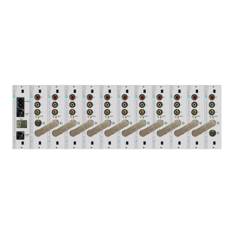
Class II symbol
Earth symbol of the antenna system

pag10
Chapter 3 WEB NMS Operation
User not only can use front buttons to set configuration, but also can control and set
the configuration in computer by connecting the device to web NMS Port. User
should ensure that the computer’s IP address is different from the SIG7412 T MPEG2’s IP address;
otherwise, it would cause IP conflict.
3.1 Encoder login
The default IP address of this device is 192.168.0.136. (We can modify the IP through the front
panel.)
Connect the PC (Personal Computer) and the device with net cable, and use ping command to
confirm they are on the same network segment.
I.G. the PC IP address is 192.168.99.252, we then change the PC IP to 192.168.0.xxx (xxx can be 1
to 254 except 136 to avoid IP conflict).
Use web browser to connect the device with PC by inputting the Encoder & Modulator’s IP address
in the browser’s address bar and press Enter.
It will display the Login interface as Figure 1. Input the Username and Password
(Both the default Username and Password are “admin”.) and then click “LOGIN” to start the device
setting.
Figure 1

pag11
3.2 Encoder Modulator Operation
Status
When we login into encoder module, it displays the status interface as Figure 2.
Figure 2
User can click any item here to enter
the corresponding interface to check
information or set the parameters.
Current software version
information
12

pag12
Figure 3
General settings for
the Encoding
program: User can
edit any item listed
as needed.
Video Status read area
Parameters → Module 1
SIG7412 T MPEG2 support up to 12 CVBS input. From the menu on left side of the
webpage, clicking “Module 1”, it displays the information of each encoding channel as
Figure 3.
12

pag13
Figure 4
Parameters → Tuner:
From the menu on left side of the webpage, clicking “Tuner”, it displays the interface
where users can configure the Tuner input parameters as Figure 4.
12

pag14
Figure5
Parameters → TS Config:
From the menu on left side of the webpage, clicking “TS Config”, it displays the interface
where users can configure the TS output parameters.
TS Config→Output TS X:
From the menu on up side of the webpage, clicking “Output TS X”, it displays the
interface where users can select the TS output carrier (Figure 5)
Figure 5
12

pag15
Input rea
Output rea
Operation rea
TS Config→Stream select:
From the menu on up side of the webpage, clicking “Stream select”, it displays the
interface where users can select program(s) to multiplex out and modify program info.
(Figure 6)
Figure 6
12

pag16
Similarly, user can cancel the multiplexed programs from the right box.
To select all the input programs
To select all the output programs
To parse programs time limitation of parsing input programs
Program Modification:
The multiplexed program information can be modified by clicking the program in the
‘output’ area. For example, when clicking , it triggers a dialog box
(Figure 7) where users can input new information.
Figure 7
Configure ‘Input Area’ and ‘Output Area’ with buttons in ‘Operation Area’. Instructions are
as below:
: To edit the input channel
: To delete the input channel
: To delete all inputs channel
: To check input IP lock or not, green means current IP locked
: To check current TS overflow or not, red color means current TS
overflow, need reduce program
: To filter/not filter the source CAinformation
: To enable/disable the PID remapping
To refresh the input program information
To refresh the output program information
Select one input program first and click this button to transfer the selected
program to the right box to output.

pag17
Figure 8
TS Config→General:
From the TS Config menu on up side of the webpage, clicking “General”, it displays the
interface where users can set output mode, enable PSI/SI table out, NIT insert/VCT insert,
PCR correction. (Figure 8)
12

pag18
Figure 9
TS Config→PID Bypass:
From the TS Config menu on up side of the webpage, clicking “PID Bypass”, it displays
the interface as Figure9 where user can add PIDs to be passed, click the “+” symbol, input
current IP channel number, then input current IP source Pid and output Pid which is
customer needed , then click “set”
12

pag19
Parameters → Modulator:
From the menu on left side of the webpage, clicking “Modulator”, it will display the
Modulator Configuration screen as Figure 10. Here user can set modulation parameters.
Figure 10
Quickly Config
Channel Config
12

pag20
Parameters → IP Stream:
SIG7412 T MPEG2 supports TS to output in IP (Max 128 IP) format through the DATA1
and DATA2 port.
Click ‘IP Stream’, it will display the interface where to set IP out parameters (Figure 11).
Figure 11
Quickly Config
Channel Config
12
This manual suits for next models
1
Table of contents
Languages:
Other Fracarro Modulator manuals

Fracarro
Fracarro MOD90 User manual

Fracarro
Fracarro Head Line SIG7280 User manual

Fracarro
Fracarro KM User manual

Fracarro
Fracarro MOD90S User manual

Fracarro
Fracarro D-Matrix 4S EVO User manual

Fracarro
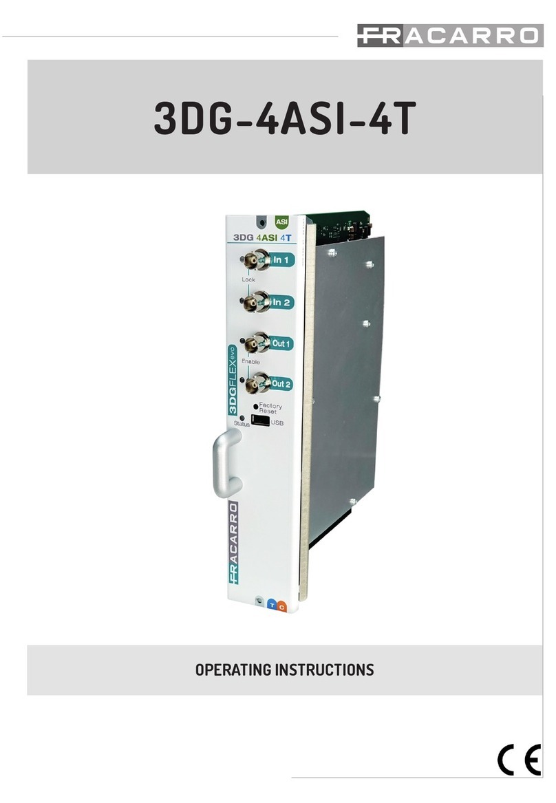
Fracarro 3DG-4ASI-4T User manual

Fracarro
Fracarro MOD-HDTV MICRO User manual

Fracarro
Fracarro MOD-HDTV User manual

Fracarro
Fracarro MOD-DVB-TC User manual