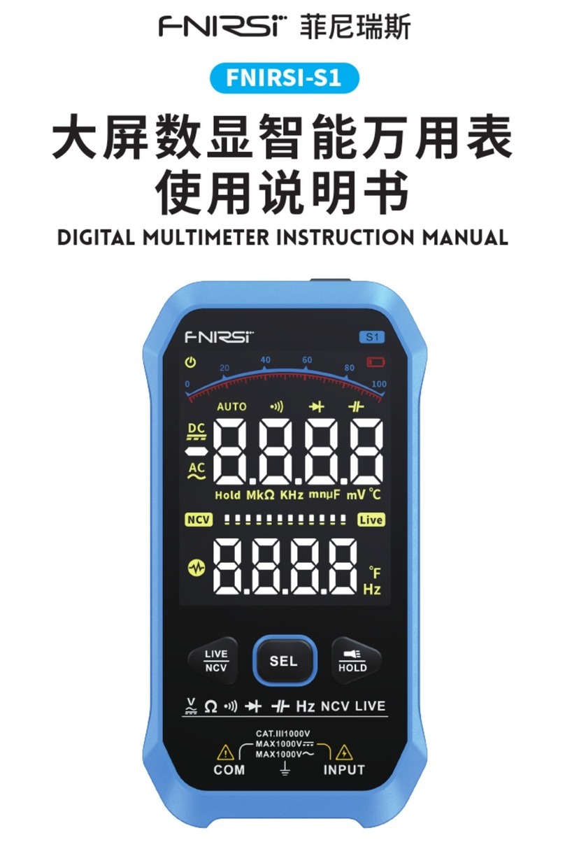
Fnirsi FNIRSI-S1 User manual

ENIS
ERG
KENIRSIS1
À
KRELER
AR
(5E
FB
ijt
BA
F2
DIGITAL
MULTIMETER
INSTRUCTION
MANUAL


CATALOG
NOTICE
TO
USER
>>>
01
1.
INTRODUCTION
>>>
o1
2.SAFETY
INSTRUCTIONS
>>>
o1
3.INSTRUMENT
DESCRIPTION
>>
04
4.
OPERATION
INSTRUCTIONS
>>>
05
5.TECHNICAL
INDICATORS
>>»
10
6.INSTRUMENT
MAINTENANCE
>»
14
7.PRODUCTION
INFORMATION
>>»
14

NOTICE
TO
USER
@P
lease
read
this
instruction
manval
and
operatien
instructions
carefuliy,Fol-
low
the
instructions
in
the
manual„In
order
to
make
the
detector
function
fully.
@p
case
keep
this
manual
®@oont
use
this
equioment
In a
flammoble
and
explosive
environment.
@keplacee
used
batteries
and
discardec
instruments
cannot
be
disposed
of
with
household
waste
Please
handle
according
to
relevant
national
or
local
laws.
@ten
there
are
any
quality
problems
with
the
instrument
or
questions
about
using
the
instrumentYou
can
contact
“FIRS”
online
customer
servic.
L.INTRODUCTION
This
product
is
a
handheld
large
screen
digital
isolay
smart
multimeter.
It
has
the
advantages
of
fast
measurement
data,
large-screen
LCD
dual
display,
lighting,
and
easy
reading
by
users
t
has
unctions
such
as
overload
protection,
and
battery
undervoltage
indication.
Whether
it
is
used
by
professionals,
factories,
schoals,
habhyists
or
families,
itis
a
ratianal
think
of
the
mult+-func-
instrument.
The
overvoltage
standard
is
CAT
IL
1000V.
2.SAFETY
INSTRUCTIONS
When
using
this
instrument,
the
user
must
follow
al
standard
safety
procedures
regarding:
1LSafety
regulations
to
prevent
electrie
shock
210
ensure
your
personal
safety,
vse
the
test
pens
provided
wien
the
meter.
Before
use,
check
and
make
surethey
arein
good
condition.

1.SAFETY
PRECAUTIONS
@use
the
meter
near
the
equipment
with
large
electromagnetic
interference,
the
reading
of
the
meter
will
be
unstable,
and
even
may
produce
larger
errors
®@oo
no
use
when
the
appearance
of
the
meter
or
test
leadsis
damaged.
©
(ne
instrument
is
not
used
correcly,
the
safety
function
provided
by
the
Insrumentmay
be
invalid.
©
Biereme
care
must
be
taken
when
working
around
exposed
conductors
or
busses,
©:
is
forbidden
to
use
thisinstrument
near
explosive
gas,
steam
or
dust.
@The
correct
input
terminal,
function
and
range
must
be
used
lor
measure-
ment.
The
input
value
must
not
exceed
the
input
limit
value
specfied
in
each
range
to
prevent
damage
to
the
instrument.
@ren
che
meter
is
connected
to
the
ine
under
test,
do
not
touch
the
unused
input
terminals
@ven
the
measured
voltage
exceeds
the
rms
value
of
6OV
DC
or
30V
AC,
be
careful
to
prevent
electric
shock.
@ten
measuring
with
a
test
lead,
place
our
finger
behind
the
protective
ring
ofthe
test
lead,
@scfore
changing
the
range,
make
sure
that
the
test
lead
has
left
the
circuit
under
test.
@ror
all
DC
functons,
In
order
to
avoid
the
risk
cf
electric
shock
due
to
possible
incorrect
readings,
please
use
the
AC
function
first
to
confirm
whether
there
is
any
AC
voltage.
Then,
select
a
DC
voltage
range
that
is
equal
to
or
greater
than
the
AC
voltage
®c'ore
performing
resistance
measurement
or
continuity
test,
the
power
supply
ef
the
circuit
under
test
must
be
cut
off,
and
all
high-valtage
copacitors
in
te
ereuit
under
test
must
ve
discharged
®@Do
no:
measure
resistance
or
conduct
continurty
tests
on
live
circuits.
®po
no:
put
iin
an
explosive
and
flammeble
place
when
not
in
use.
@ren
repairing
Tv
sets
or
measuring
power
conversion
circuits,
be
careful
of
high-ampliude
voltage
pulses
in
the
circuit
under
test
to
avoid
damage
to
the
meter.

@riis
product
uses
3.7V/1000mA
thium
battery
for
power
supply,
and
the
battery
must
be
orractiy
Installed
in
the
battery
box
ofthe
instrument
@vren
the
battery
undervoltage
symbol
appears,
please
charge
it
in
time.
A
low
battery
can
causa
the
meter
to
read
incorrecty,
which
could
resultin
electric
shock
or
personal
injury
@in
the
measurement
category,
the
voltage
measurement
should
not
exceed
1000.
®@oa
no
use
the
instrument
when
the
protective
case
lor
part
of
if)
is
removed.
2.
SAFETY
MAINTENANCE
HABITS
@uten
opening
the
case
ofthe
instrument
or
removing
the
battery
covar,
the
test
lead
should
be
pulled
out
first
@uten
repaiing
the
insttument,
be
sure
to
use
the
designated
replacement
pars
@Betore
turning
on
the
Instrument,
yau
must
disconnect
all
related
power
sources,
and
you
must
also
ensure
that
you
do
not
have
static
electricity
to
prevent
damage
lo
the
components
ofthe
instrument.
@ro:
accurate
and
correct
calibration
or
maintenance
of
the
instrument,
you
should
return
it
to
the
factory,
@uihen
opening
the
case
af
the
meter,
It
must
be
noted
that
zome
capacitors
in
the
meter
still
hold
dangerous
voltages
even
after
the
meter
is
powered
off
©:
cy
abnormelity
is
observed
in
the
instrument,
the
instrument
should
be
stapped
immediately
and
sent
for
repair
And
make
sure
ihat
it
cannot
be
used
untlit
passes
the
inspection.
@\'hen
not
in
use
fora
ong
time,
and
avoid
storingin
places
with
high
tempera-
ture
and
high
humidity.
3.
INPUT
PROTECTION
MEASURES
@uren
performing
voltage
measurements,
the
maximum
input
voltage
that
‘can
withstand
is
1000V,
either
DC
or
AC
@Can
withstand
no
more
than
250VAC
voltage
or
equivalenteffectve
valve
voltage.

3.INSTRUMENT
DESCRIPTION
nresr
[eN
e
od
dienen
we
e
©
charging
port
(5\-14)
©
LCD
Monitor
©
red
test
pen
input
©
charging
indicator
©
Nov
andLVE
buttons
©
NCV
sensing
area
(redlightforcharging,
_@
SEL
button
®
flashlight
green
lightforful)____@
Data
hold
and
flashlightbuttons
®
on/off
Button
©
biacktest
pen
input

BUTTON
DESCRIPTION
Button
Function
Description
w
power
button
ser
Function
switch
button
Data
hold
button
and
flashlight
NCV
function
and
Livewire
function
buttons
4.OPERATION
INSTRUCTIONS
DREGULAR
OPERATION
Reading
Hold
Mode
keeps
the
current
reading
on
the
display.
The
reading
hold
mode
can
be
exited
by
changing
the
measurement
function
gear
or
pressingthe
key
again.
To
enter
ang
vit
reading
hold
mode:
L
Short
press
the”
zot
‘key,the
reading
will
be
held
and
the
symbol
will
be
‘displayed
on
the
LCD
HOLD
display
at
{he
same
time.
2.Short
press
the”
ment
state,
5
”
key
again
to
restore
the
meter
lo
lie
normal
messure-
3Longoress”
soe
*
to
turn
on
the
fashlight,
and
then
long
press
to
turn
off
the
ashlight
4.Pressthe”
ev
*
key
to
perform
NCV
measurement.
Press
the”
gev
”
key
again
to
enterthe
live
wire
(LIVE)
measurement.

AUTOMATIC
MEASUREMENT
®@o-
nat
mezsure
any
voltage
higher
than
1000V
DC/L000V
AC
to
prevent
electrie
shoek
or
damage
to
the
instrument.
@po
not
apply
more
than
1000V
DC
veltage/L0COV
AC
voltage
between
the
common
terminal
and
the
ground
to
avoid
electric
shock
or
damage
to
the
instrument.
Inautomatie
mode,
AC
and
DC
voltage,
resistance
and
continuity
can
be
automati-
cally
measured.
L
After
power
on,
it
will
automatically
switch
to
"AUTO"
automatic
measurement
mode.
2.
Connect
he
black
test
lead
and
the
red
test
lead
to
the
COM
input
jack
and
the
INPUT
input
jack
respectively,
3.Use
the
test
pen
to
measure
thevoltage
value,
resistance
value
and
shortcircuit
pointofthecircuir
to
betested
at
both
ends,
(parallel
tothe
circuit
under
test)
4.
At
this
time,
the
liquid
erystal
display
wil
display
the
corresponding
measured
voltage
value
and
resistance
value
atthe
sametime.
When
measuring
DC
voltage,
the
display
will
show
the
voltage
polarty
connected
to
the red
test
lead
at
the
same
time.
If
the
measured
resistance
value
is
ess
than
500,
the
buzzer
will
issue
on
alarm
sound
When
the
measured
DC
voltage
is
less
than
075V
and
the
AC
voltage
is
less
than
075V,
the
displayed
resistance
valus
may
appear,
beeause
the
minimum
measurement
voltage
value
of
this
product
is
0.75V,
and
the
minimum
AC
voltage
is
0.75,
1.
Whien
measuring
low
resistance,
in
order
to
measure
eccurately,
please
first
short-circuit
the
two
test
leads
to
read
the
short-cireuit
resistance
value
of
the
test
leads,
and
subsract
the
resistance
valve
after
measuring
the
measured
resistance.

2
In
the
10M
range,
it
will
take
a
few
seconds
for
the
reading
to
stabilize,
This
is
normal
or
high
resistance
measurements
3.
When
the
meter
is
open
circuitor
the
resistance
value
of
the
measured
object
is
too
large,
the
display
will
display
"OL
indicating
that
the
measured
value
exceedsthe
range
NCV
TEST
Pressthe
BE
key
place
the top
of
the
meter
close
to
the
conductor,
if
the
meter
derects
AC
voltage,
the
meter
will
The
signal
strength
of
‚
when
the
sensed
voltage
is
low
,
the
screen
signl
wil
display
law:
MIE
‚
medium:
WINN
high:
„and
at
the
same
time
the
buzzer
emits
alarm
sounds
of
different
frequencies.
@even
without
indication,
voltage
may
still
be
present.
Do
not
rely
on
non-contact
voltage
detectors
to
determine
lead
Whether
there
is
voltage
on
the
ine.
Probing
operations
mayvary
by
socket
design,
Insulation
thieknass
and
type,
ete
influence
ef
factors.
@uhen
the
input
terminal
of
he
meter
enters
the
voltage,
the
buzzer
will
also
sound
due
to
the
existence
of
the
induced
voltage
sound.
©
interference
sources
in
the
external
environment
(such
as
flashlight,
ete.)
may
flsely
trigger
the
non-contact
voltage
detection.

DFIREWIRE
TEST
Short
Press
HE
pressthe
button
twice,
the
screen
displays
LIVE,
insert
the
red
test
pen
into
the
INPUT
end,
and
the red
pen
in:o
the
power
socket,
the
meter
displays
LIVE,
which
is
the
(ive
wire.
DIODE
MEASUREMENT
LAfter
power
on,
t
wlllautomaticaliy
switch
to
the
‘AUTO
automatic
measure-
ment
made,
and
then
press
the
SEL
key
to
switch
to
the"
«9))
Bp
"diode
measurementmade
2.
Connect
theblacktest
lead
and
the
red
testlead
to
the
COM
inputjack
and
the
INPUT
input
jack
respectively.
3.
Connect
theblacktest
lead
and
the red
test
lead
to
both
endsof
the
object
to
be
tested.
A,
IF
the
measured
object
is
à
diode,
the
red
and
black
test
leads
should
be
placed
on
the
positive
and
negative
ends
of
the
diode
respectively,
and
the
meter
wl
display
the
pasitivebies
value
ofthe
tested
diode.
Ithe
polartyofthe
test
leads
is
reverzed
orthe
test
points
are
connected
ifthe
polartyofthetubes
is
reversed,
the
meter
will
display
"OL!
In
the
circuit,
normal
diode
should
produce
a
forward
voltage
drop
of
0.5
to
OBV;
but
the
reading
of
the
reverse
bias
voltage
will
depend
on
the
change
in
the
resistance
value of
the
other
channels
between
the
twotest
leads.
CAPACITANCE
MEASUREMENT
1
After
power
on,
it
will
automatically
switch
to
the
'AUTO"
avtomatie
measurement
made,
and
then
press
the
SEL
button
to
switch
to
the
cepacitence
measurement
mode.
2.
Connectthe
black
test
laad
and
the
red
test
lead
to
the
COM
input
jack
and
the
INPUT
inoutjack
respectively.
3.
Use
a
test
lead
to
measure
the
capacitance
value
of
the
capacitor
to
be
measured
at
both
ends
and
read
the
measured
valve
from
the
LCD,

@hen
measuring
large
capacitances,
it
will
take
sometime
for
thereading
|
tostobilze
uiten
measuring
polarized
capacitors.
pay
attention
to
the
correspond
ing
polarityto
avoid
damage
to
the
meter.
DFREQUENCY
MEASUREMENT
LAfter
power
on,
it
will
automatically
switch
to
the
"AUTO"
automatic
mess
the
SEL
key
to
switch
to
the
frequency
Hz
measur
ment
made,
and
then
pres
ment
mode
2.connecttheblack
test lead
and the
red
testlead
to
the COM
inputjack
and
the
INPUT
input
jack
respectively
3.
Use
both
ends
of
the
test
pen
to
read
the
measured
display.
B)
TEMPERATURE
MEASUREMENT
LAfter
power
on,
it
willautomatically
switch
to
the
"AUTO"
automatic
measure
ue
from
the
LCD
ment
mode,
and
hen
press
the
SEL
ke
touch
(the
measurement
mode.
2.
connect
theblack
input
terminal
of
the
thermocouple
and the
red
test
lead
to
the
COM
input
jack
and
the
INPUT
input
jack
respectively.
Fahrenheit
is
displayed
along
with
the
temperature
valve.
3.
The
LCD
display
reads
the
measured
value.
there
is
inductive
impedance
in
the
line,
there
will
be
flutuations.
afiecting
the
results
read
and
the
data
maybe
inaccurate.
Itis
necessary
to
disconnect
thetest,
and
the
correct
test
data
will
be
obtained.

5.TECHNICAL
INDICATORS
DCOMPREHENSIVE
INDICATORS
@10a0v
CAT.
1
pollution
degree:
2
@nisitude
-2000m
@
working
environment
temperature
and
humidity:
0-40
°C
(<80%
RH,
not
considered
when
<10
“C).
@storzge
environment
temperature
and
humidtò
removethe
battery).
@remperature
caefieient:0.1
accuracyy"C
(<18°C
or
>28°C})
:
10-60
'C
(70%
RH,
@tzximum
olowable
voltage
between
measuring
terminal
and
earth:
1000V
Dc
or
1000v
AC
Rus
®@
converson
rate:
about
3
times
/
second
@oisplzy:
LCD
display
with
a
masimum
of
9999
counts,
which
isautomatically
displayed
according
to
the
measurement
function
unit
symbol
®overrange
indication:
LCD
lay
“OL”
®@eartery
low
voltage
indication:
When
the
battery
voltage
Is
lowar
than
the
normal
working
voltage,
*
ED
”
will
be
displayed.
@indicztion
of
input
polarity:"-"is
displayed
automaticaly
@po
er
supply:
rechargesble
lithium
battery
(37/1000)
Note:
The
device
is
not
available
in
the
power-on
stata,
and
the
display.
#
atthis
time,
unplug
the
charger
and
automatically
switch
to
the
normal.
measurement
made.
®Dimensions:
143mm”75mm”
mm
eight:
zbout
1308
(including
battery)
ACCURACY
INDEX
(reading
+
word)
the
warranty
periad
is
one
year
from
thedate
ofdelivery.
Baseline
conditions:
ambient
temperature
19°C
to
28°C,
relative
humidity
nt
greater
than
80%.
1

21
DC
VOLTAGE
Ees
maimum
value)
|
Resolution
Accuracy
o-0v
ooouv
+
(0.8%
reading
+3
digits)
10-100V
vom
+
(0.8%
reading
+3
digits)
100-1000v
ov
+
(0,5%
reading
+3
digits)
zoo0v
av
(1.29
reading
+3
cgs)
Maximum
input
voltage:
1000
DC
RMS
Minimum
measurement
voltage:0.75VDC
switch
the
auto
range
mode
in
the
smart
mode
Press
the
SEL
buttonto
22
AC
VOLTAGE
Range
(ercleting
masimam
vatue)
|
Resolution
Accuracy
oov
ooo
2
(080%
reading
+
3digits)
10-100v
ov
2
(08%
reading
+
3digits)
100-1000v
oav
=
Gs
reading+
zolgie)
1000v
ww
=
2
reading
+
scgis)
Maximum
input
voltage:
1000V
DCRNS
Minimum
measurement
voltage:
0.75VOC
Frequency
response:
50HZ-IKHZ
rue
RMS
Press
the
SEL
button
to
switch
the
auto
range
mode
in
the
smart
mode
u

2.3
RESISTANCE
24
BEEP
ON
AND
OFF
Rane
anna
sztu)
|
Resolution
Accuracy
0-10000
0.10
+
(0.8%
reading
+3
digits)
1k-100kO
ook
+
(0,8%
reading
+3
digits)
10ok-1009k
aa
&
(0806
reading
+3
digits)
1M-100M
oo1ma
(12%
reading
+3
digits)
‘Overload
protection:
250%
DE/AC
Function)
Range
|Resolution
‘Test
Conditions.
jj
|
zoon
Resistance
not
oan
|
gresterthanson
|
Open
circuit
Built-in
buzzer
voltage
About
04V
sounds
continuously
Overload
protection:250V
DC/AC
2.5
TEMPERATURE
Range
Resolution
Accuracy
20e
re
4
(5,0%
reading
+4
digits)
reaoor
re
(1.096
reading
+3
egte)
401°c-100re
ve
+
(2
noa
reading
+5
digits
NEF
ve
(5
ooh
reading
+
digits)
LEFF
vr
+
(109%
reading
+6
digits)
T538°F-1832F
Yr
+
(20%
reading
+10
digits)

2.6
CAPACITANCE
ROE
enaamonuid
|
Resolution
Accuracy
ozon
aoonnr
zooo
oomr
100-1090nF
oaf
1p-LOuF
0.001F
+t(4.5%
reading
+Sdigits)
zor10our
oor
1004-10004F
OluF
mome
voor
Overload
protection:
250V
DC/AC
2.7
FREQUENCY
RN
erasmus,
|
Resolution
Accuracy
Ozone
voort
20-1002
oon
100-1000#z
onz
erk
ooomz
|
0.106
reading
+3digies)
10k100kHz
OOk
zook-100otiz
Okt
1000ktz-10MHz
uz
Input
Sensitivity:
L5VRNS
Overload
Protection:
250V
DC
or
AC
Peak(no
more
than
10
seconds)
freauency
measurement
BE

28
DIODES
[_Function
|
resolution
|
Test
conditions
Forward
DC
current:
about
ImA
Open
reu
voltage
aout
AV
Bp
|
cor
|
mede
Approximate
value
of
forward
voltage
drop
Overload
protection
:250V
DC/AC
6.INSTRUMENT
MAINTENANCE
@Rezularly
clean
the
meter
case
with
a
damp
cloth
and
>
small
amount
of
detergent,
do
not
usa
abrasives
or
chemical
solvents.
@D
ty
or
wetinput
jacks
may
affect
readings.
@roctean
input
jacks:
LTumm
off
the
meter
and
unplug
al
test
leads
trom
the
input
jacks.
2.
Remove
all
dirt
from
the
jack
3.Use
a
new
cotton
balldipped
in
detergent
or
lubricant
to
clean
esch
socket,
the
lubricant
can
prevent
and
moisture
related
jack
contamination,
7.CONTACT
US
Any
FNIRSI'users
with
anyquestions
who
comes
to
contact
us
wiil
have
our
promise
to
get
asatisfactory
solution
+
an
Extra
6-Month
Warranty
to
thanks,
for
yoursupport!
By
the
way,
We
have
created
an
interesting
community,
welcome
to
contact
FNIRSI
staff
to
join
our
community.
Shenzhen
FNIRSI
Technology
Co.‚LTD.
'Add.:Westof
Buding
C‚Welda
Industrial
Park,
Dalang
street,
Longhua
District,Shenzhen,Guangdong
E-mail
:fnirsiafficial@gmal.
com
(Business)
[email protected]{Equipment
service)
‘el:0755-83242477
+86135368EAG8G
http://www
friesen
4


TRAP
FMM
Dowmlead
User
manusl&APP&Software
Other manuals for FNIRSI-S1
1
Table of contents
Other Fnirsi Multimeter manuals
