TC Communications TC8518 T1 User manual

TC8518 T1/E1, Voice/Data & 10/100
Base-T Ethernet Fiber Optic
Multiplexer
User Manual
MNL-85180-01-22

2 TC8518 Rev 2.2 User Manual
All Rights Reserved
Copyright 2011 by TC Communications. Products described in this publication are protected by
one or more U.S. and foreign patents.
Trademarks
The TC Communications logo is a registered trademark.
JumboSwitch is a registered trademark of TC Communications.
Other product and brand names may be trademarks or registered trademarks of their respective owners.
Documentation Disclaimer
This document is provided “as-is” and is to be used only as a general guide. TC Communications disclaims all
warranties, express or implied, regarding the accuracy of the information. TC Communications shall not be liable for
any indirect, special, incidental, or consequential damages (including damages for loss of business, loss of profits,
loss of business information, business interruption or other pecuniary loss) arising out of errors in this document.
The information given in this document is reviewed regularly and any necessary corrections will be included in
subsequent editions. We appreciate any suggested improvements. We reserve the right to make technical
improvements without notice.
Dissemination or reproduction of this document, or evaluation and communication of its contents, is not authorized
except where expressly permitted. Violations are liable for damages. All rights reserved, particularly for the
purposes of patent application or trademark registration. This document contains proprietary information, which is
protected by copyright. All rights are reserved. No part of this document may be photocopied, reproduced or
translated to another language without the prior written consent of TC Communications.
Record of Revisions
Revision Date Description of Changes
1.0 10/22/07 Initial Release of TC8518.
2.0 09/23/10 Add voice and data option.
2.1 02/07/12 Update local/remote loop back instructions.
2.2 01/29/14 Updated rear expansion images.
TC Communications
17881 Cartwright Road
Irvine, California U.S.A. 92614
Tel. (949) 852-1972
Fax (949) 852-1948
E-Mail: sales @tccomm.com
Website: www.tccomm.com

TC8518 Rev 2.2 User Manual 3
Guide to Alert Symbols
These alert symbols are used in Caution, Warning, and Danger notes.
Symbol Meaning
Pinching or crushing hazard
Electrical hazard.
Equipment alert: be careful of
damage from static electricity
General alert: used for all
other hazardous conditions
(referring to people, not
equipment).

4 TC8518 Rev 2.2 User Manual

TABLE OF CONTENTS
TC8518 Rev 2.2 User Manual TOC-1
1Introduction
1.1 Introduction. . . . . . . . . . . . . . . . . . . . . . . . . . . . . . . . . . . . . . . . . . . . . . . 1-1
1.2 General Information . . . . . . . . . . . . . . . . . . . . . . . . . . . . . . . . . . . . . . . . 1-2
1.3 TC8518 Product Description . . . . . . . . . . . . . . . . . . . . . . . . . . . . . . . . . 1-2
1.3.1 Features . . . . . . . . . . . . . . . . . . . . . . . . . . . . . . . . . . . . . . . . . . . . . . 1-3
1.3.2 Environment . . . . . . . . . . . . . . . . . . . . . . . . . . . . . . . . . . . . . . . . . . . 1-8
1.3.3 Power . . . . . . . . . . . . . . . . . . . . . . . . . . . . . . . . . . . . . . . . . . . . . . . . 1-8
1.3.4 Management. . . . . . . . . . . . . . . . . . . . . . . . . . . . . . . . . . . . . . . . . . . 1-8
1.3.5 Specifications (TC8518) . . . . . . . . . . . . . . . . . . . . . . . . . . . . . . . . . 1-10
1.3.6 Pin Assignments, Configurations and Default Settings. . . . . . . . . . 1-12
1.3.7 Default Software Configuration. . . . . . . . . . . . . . . . . . . . . . . . . . . . 1-15
1.3.8 Default Unit Alarm Settings. . . . . . . . . . . . . . . . . . . . . . . . . . . . . . . 1-17
1.3.9 Optical Redundancy . . . . . . . . . . . . . . . . . . . . . . . . . . . . . . . . . . . . 1-17
1.3.10 Environmental & EMI Compliance . . . . . . . . . . . . . . . . . . . . . . . . . 1-19
1.3.11 Physical Dimensions. . . . . . . . . . . . . . . . . . . . . . . . . . . . . . . . . . . . 1-20
2 Installation
2.1 General Information . . . . . . . . . . . . . . . . . . . . . . . . . . . . . . . . . . . . . . . . 2-1
2.2 Unpacking . . . . . . . . . . . . . . . . . . . . . . . . . . . . . . . . . . . . . . . . . . . . . . . 2-1
2.3 Environmental Requirements. . . . . . . . . . . . . . . . . . . . . . . . . . . . . . . . . 2-1
2.3.1 Equipment Location . . . . . . . . . . . . . . . . . . . . . . . . . . . . . . . . . . . . . 2-1
2.4 Mechanical Installation. . . . . . . . . . . . . . . . . . . . . . . . . . . . . . . . . . . . . . 2-2
2.4.1 19-Inch Rack Mounting. . . . . . . . . . . . . . . . . . . . . . . . . . . . . . . . . . . 2-2
2.4.2 Power Supplies. . . . . . . . . . . . . . . . . . . . . . . . . . . . . . . . . . . . . . . . . 2-2
2.5 Unit Power . . . . . . . . . . . . . . . . . . . . . . . . . . . . . . . . . . . . . . . . . . . . . . . 2-4
2.5.1 Powering on the TC8518 . . . . . . . . . . . . . . . . . . . . . . . . . . . . . . . . . 2-4
2.6 Cabling. . . . . . . . . . . . . . . . . . . . . . . . . . . . . . . . . . . . . . . . . . . . . . . . . . 2-4
2.7 Quick-Start Guide. . . . . . . . . . . . . . . . . . . . . . . . . . . . . . . . . . . . . . . . . . 2-5
2.7.1 Installation Procedure Summary. . . . . . . . . . . . . . . . . . . . . . . . . . . . 2-5
3 Management through the Web
3.1 Introduction. . . . . . . . . . . . . . . . . . . . . . . . . . . . . . . . . . . . . . . . . . . . . . . 3-1
3.2 Setup . . . . . . . . . . . . . . . . . . . . . . . . . . . . . . . . . . . . . . . . . . . . . . . . . . . 3-1
3.3 Home Page . . . . . . . . . . . . . . . . . . . . . . . . . . . . . . . . . . . . . . . . . . . . . . 3-2
3.3.1 Home: Physical Status . . . . . . . . . . . . . . . . . . . . . . . . . . . . . . . . . . . 3-3
3.3.2 Home: Unit Alarm . . . . . . . . . . . . . . . . . . . . . . . . . . . . . . . . . . . . . . . 3-4
3.3.3 Home: Unit Alarm: Alarm Trigger Criteria. . . . . . . . . . . . . . . . . . . . . 3-5
3.4 Basic Settings. . . . . . . . . . . . . . . . . . . . . . . . . . . . . . . . . . . . . . . . . . . . . 3-7
3.5 IP Settings . . . . . . . . . . . . . . . . . . . . . . . . . . . . . . . . . . . . . . . . . . . . . . . 3-8
3.5.1 IP Address Aliases . . . . . . . . . . . . . . . . . . . . . . . . . . . . . . . . . . . . . 3-10
3.6 Advanced . . . . . . . . . . . . . . . . . . . . . . . . . . . . . . . . . . . . . . . . . . . . . . . 3-10
3.6.1 Advanced: About TC8518. . . . . . . . . . . . . . . . . . . . . . . . . . . . . . . . 3-11
3.6.2 Advanced: Configuration File . . . . . . . . . . . . . . . . . . . . . . . . . . . . . 3-12
3.6.3 Advanced: Reboot . . . . . . . . . . . . . . . . . . . . . . . . . . . . . . . . . . . . . 3-17
3.6.4 Advanced: Restore Defaults. . . . . . . . . . . . . . . . . . . . . . . . . . . . . . 3-18
3.6.5 Advanced: Firmware Upgrade . . . . . . . . . . . . . . . . . . . . . . . . . . . . 3-19
3.6.6 Advanced: Upgrade From a Computer on the Network . . . . . . . . . 3-19
3.7 Simple Network Management Protocol (SNMP) Settings . . . . . . . . . . 3-20

TABLE OF CONTENTS
TOC-2 TC8518 Rev 2.2 User Manual
3.8 Login Settings. . . . . . . . . . . . . . . . . . . . . . . . . . . . . . . . . . . . . . . . . . . . 3-21
3.9 T1/E1 Options . . . . . . . . . . . . . . . . . . . . . . . . . . . . . . . . . . . . . . . . . . . 3-23
3.9.1 T1/E1 Options: Status. . . . . . . . . . . . . . . . . . . . . . . . . . . . . . . . . . . 3-23
3.9.2 T1/E1 Options: Settings . . . . . . . . . . . . . . . . . . . . . . . . . . . . . . . . . 3-23
3.9.3 T1/E1 Options: Statistics. . . . . . . . . . . . . . . . . . . . . . . . . . . . . . . . . 3-24
3.9.4 T1/E1 Options: Statistics Error Seconds Total . . . . . . . . . . . . . . . . 3-25
3.9.5 T1/E1 Options: Statistics History . . . . . . . . . . . . . . . . . . . . . . . . . . 3-26
3.9.6 T1/E1 Options: Diagnostics . . . . . . . . . . . . . . . . . . . . . . . . . . . . . . 3-27
3.10 Optical Options. . . . . . . . . . . . . . . . . . . . . . . . . . . . . . . . . . . . . . . . . . . 3-28
3.10.1 Optical Options: Optical Status. . . . . . . . . . . . . . . . . . . . . . . . . . . . 3-28
3.10.2 Optical Options: Optical Settings . . . . . . . . . . . . . . . . . . . . . . . . . . 3-29
3.10.3 Optical Options: Statistics. . . . . . . . . . . . . . . . . . . . . . . . . . . . . . . . 3-30
3.11 Ethernet Options . . . . . . . . . . . . . . . . . . . . . . . . . . . . . . . . . . . . . . . . . 3-31
3.11.1 Ethernet Options: Port Settings . . . . . . . . . . . . . . . . . . . . . . . . . . . 3-31
3.11.2 Ethernet Options: Rate Limit. . . . . . . . . . . . . . . . . . . . . . . . . . . . . . 3-32
3.11.3 Ethernet Options: Port Statistics. . . . . . . . . . . . . . . . . . . . . . . . . . . 3-33
3.11.4 Ethernet Options: Port Statistics: Port History . . . . . . . . . . . . . . . . 3-34
3.11.5 Ethernet Options: Port Statistics: Event Statistics . . . . . . . . . . . . . 3-35
3.11.6 Ethernet Options: Ethernet over Fiber . . . . . . . . . . . . . . . . . . . . . . 3-36
3.12 Logout . . . . . . . . . . . . . . . . . . . . . . . . . . . . . . . . . . . . . . . . . . . . . . . . . 3-38
4 Command Line Interface
4.1 Introduction. . . . . . . . . . . . . . . . . . . . . . . . . . . . . . . . . . . . . . . . . . . . . . . 4-1
4.2 Setup . . . . . . . . . . . . . . . . . . . . . . . . . . . . . . . . . . . . . . . . . . . . . . . . . . . 4-1
4.3 Console/Telnet Management. . . . . . . . . . . . . . . . . . . . . . . . . . . . . . . . . 4-3
4.3.1 IP Settings. . . . . . . . . . . . . . . . . . . . . . . . . . . . . . . . . . . . . . . . . . . . . 4-4
4.3.2 Login Settings. . . . . . . . . . . . . . . . . . . . . . . . . . . . . . . . . . . . . . . . . . 4-4
4.3.3 Advanced Settings . . . . . . . . . . . . . . . . . . . . . . . . . . . . . . . . . . . . . . 4-5
4.3.4 Firmware Update . . . . . . . . . . . . . . . . . . . . . . . . . . . . . . . . . . . . . . . 4-5
4.3.5 Serial Port Setting (Apply to Serial Expansion Card) . . . . . . . . . . . . 4-6
4.3.6 Phone Port Settings (Applies to Phone expansion card) . . . . . . . . . 4-7
5 SNMP Management
5.1 Introduction. . . . . . . . . . . . . . . . . . . . . . . . . . . . . . . . . . . . . . . . . . . . . . . 5-1
5.2 SNMP Query . . . . . . . . . . . . . . . . . . . . . . . . . . . . . . . . . . . . . . . . . . . . . 5-1
5.3 SNMP Third Party Management Software. . . . . . . . . . . . . . . . . . . . . . . 5-1
5.4 SNMP Trap Management. . . . . . . . . . . . . . . . . . . . . . . . . . . . . . . . . . . . 5-2
6 Troubleshooting
6.1 Introduction. . . . . . . . . . . . . . . . . . . . . . . . . . . . . . . . . . . . . . . . . . . . . . . 6-1
6.2 All LEDs are "OFF". . . . . . . . . . . . . . . . . . . . . . . . . . . . . . . . . . . . . . . . . 6-2
6.3 "Alarm Condition" - ALARM LED on the front panel. . . . . . . . . . . . . . . . 6-2
6.4 Optic Cable Types . . . . . . . . . . . . . . . . . . . . . . . . . . . . . . . . . . . . . . . . . 6-3
6.5 Calculating the loss on the Fiber . . . . . . . . . . . . . . . . . . . . . . . . . . . . . . 6-3
6.6 Loopback Tests . . . . . . . . . . . . . . . . . . . . . . . . . . . . . . . . . . . . . . . . . . . 6-3
6.6.1 T1/E1 Local Loopback Test . . . . . . . . . . . . . . . . . . . . . . . . . . . . . . . 6-4
6.6.2 Optical Local Loopback Test. . . . . . . . . . . . . . . . . . . . . . . . . . . . . . . 6-4
6.6.3 Ethernet Local Loopback Test . . . . . . . . . . . . . . . . . . . . . . . . . . . . . 6-4

TABLE OF CONTENTS
TC8518 Rev 2.2 User Manual TOC-3
6.6.4 T1/E1 Remote Loopback Test . . . . . . . . . . . . . . . . . . . . . . . . . . . . . 6-4
6.6.5 Ethernet Remote Loopback Test . . . . . . . . . . . . . . . . . . . . . . . . . . . 6-4
6.7 Loopback Test - Remote Ethernet . . . . . . . . . . . . . . . . . . . . . . . . . . . . . 6-7
6.8 T1/E1 CSU loop up & loop down codes. . . . . . . . . . . . . . . . . . . . . . . . . 6-8
Appendix A Return Policy
A.1 Return Policy . . . . . . . . . . . . . . . . . . . . . . . . . . . . . . . . . . . . . . . . . . . . . A-1
A.1.1 Warranty . . . . . . . . . . . . . . . . . . . . . . . . . . . . . . . . . . . . . . . . . . . . . . A-1
A.1.2 Limitation of Liability . . . . . . . . . . . . . . . . . . . . . . . . . . . . . . . . . . . . . A-2
Appendix B Safety
B.1 Overview . . . . . . . . . . . . . . . . . . . . . . . . . . . . . . . . . . . . . . . . . . . . . . . . B-1
B.2 Certified Usage. . . . . . . . . . . . . . . . . . . . . . . . . . . . . . . . . . . . . . . . . . . . B-1
B.2.1 Qualification Requirements for Personnel . . . . . . . . . . . . . . . . . . . . B-1
B.2.2 National and International Safety Regulations . . . . . . . . . . . . . . . . . B-1
B.2.3 Recycling . . . . . . . . . . . . . . . . . . . . . . . . . . . . . . . . . . . . . . . . . . . . . B-2
B.3 Power Supply. . . . . . . . . . . . . . . . . . . . . . . . . . . . . . . . . . . . . . . . . . . . . B-2
B.4 Environment. . . . . . . . . . . . . . . . . . . . . . . . . . . . . . . . . . . . . . . . . . . . . . B-3
Glossary. . . . . . . . . . . . . . . . . . . . . . . . . . . . . . . . . . . . . . . . . . . . . . . . . . . . Glossary-1

TABLE OF CONTENTS
TOC-4 TC8518 Rev 2.2 User Manual

TC8518 Rev 2.2 User Manual 1-1
Chapter 1 Introduction
1.1 Introduction
This manual contains a description of the TC8518 as a T1/E1, Data/Voice &
Ethernet Fiber Optic Multiplexer that provides T1/E1, Data/Voice & Ethernet
connectivity over fiber optics. It supports 8/12/16 channels of T1 or E1 and 3-port
Ethernet switch over single mode (1300/1550nm), or multimode fiber (1300nm).
The TC8518 has any one of these options: 8 additional T1, 4 additional E1, 8-
channel voice, 4-channel 2-wire/4-wire analog, 8-channel data (RS-232/RS-422/RS-
485).
This manual intends to:
- document items necessary to define each product and its method of
operation
- provide technical information of the functional capabilities and
performance levels necessary for system level networking designs
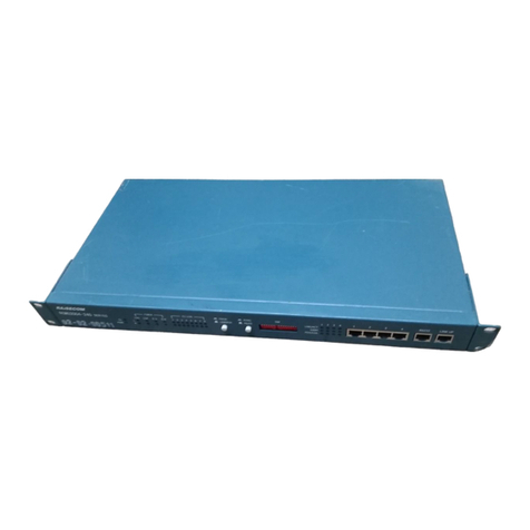
Figure 1-1 TC8518 (front)

Chapter 1 Introduction General Information
1-2 TC8518 Rev 2.2 User Manual
1.2 General Information
This manual is for the operation and maintenance of the TC8518. It is intended for
TC Communications factory-trained personnel.
1.3 TC8518 Product Description
This manual contains a description of the TC8518 as a T1/E1, Data/Voice &
Ethernet Fiber Optic Multiplexer that provides T1/E1, Data/Voice & Ethernet
connectivity over fiber optics. It supports 8/12/16 channels of T1 or E1 and 3-port
Ethernet switch over single mode (1300/1550nm), or multimode fiber (1300nm).
TC8518 has any one of these options: 8 additional T1, 6 additional E1, 8-channel
voice, 4-channel 2-wire/4-wire analog, 8-channel data (RS-232/RS-422/RS-485).
It offers advanced features, such as jitter removal and support for AMI, B8ZS
coding for T1 and AMI, HDB3 coding for E1. The TC 8518 offers optimum
flexibility, extremely low current consumption, and high reliability.
Transparent to the framing format, the TC8518's T1/E1 interface shapes the transmit
pulse to support CCITT G.703. Copper line distances for connecting T1/E1 can
range from 0 to 655 feet. The internal elastic buffer removes jitter from the
transmitted data.
Each T1/E1 channel LED indicator eases installation and facilitates troubleshooting.
These LEDs can indicate an Alarm condition, T1/E1 Signal Loss, active Sync status
and more.
The 3-Port Ethernet switch supports half/full-duplex and a combined bandwidth of
100Mbps. The TC8518 supports VLAN* and supports Ethernet Huge Frames (1916
bytes). Each T1 or E1 channel is independent, transparent to the framing format, and
supports all applicable standards and line codes( AMI, B8ZS for T1 and HDB3,
AMI for E1).
Management, setup, diagnostics, and monitoring are accessed via Web, SNMP,
Telnet or Serial Console.
The TC8518 supports fiber optic distances up to 100 km and offers an optional two-
way, "one fiber" communication option to maximize fiber cable usage. Standard
redundant power and redundant optics including automatic switchover ensure
maximum reliability.
Highly cost effective when used to multiplex T1/E1 channels & 10/100 Ethernet
over a single duplex fiber, the TC8518 is often used in interconnecting PBXs in
different buildings, extending satellite down links, transmiting beyond the normal
limitation of twisted pairs (without a repeater), or connecting cell sites to central
offices.
The TC8518 is available in basic stand-alone or 1U high rackmount. SC Optical
Connectors and RJ-48F ports are standard. Standard power is 90/260VAC and
includes redundant power supplies. Optional power sources include 24VDC,
48VDC, and 125VDC.

Chapter 1 Introduction TC8518 Product Description
TC8518 Rev 2.2 User Manual 1-3
1.3.1 Features
• Integrates Multiple T1/E1 and Ethernet Over Fiber Optics
• 8, 16, 20, or 24 Channels of T1 or 8, 16, 20 Channels of E1
• 3-Port Auto-Negotiating & Auto-Sensing Ethernet Switch (100Mbps total
bandwidth)
• Optional Voice (up to 8 channels FXS/FXO), 2-wire/4-wire analog (up to 4
channels), or Data (up to 8 channels RS-232/RS-422/RS-485)
• Ethernet VLAN* and Rate Limiting Capabilities, plus Statistics Monitoring
(T1/E1, Optics, Ethernet)
• Hi-Temp (-20 to +70) and Extreme Temp (-40 to +80) Versions (optional)
• Supports the Following Line Codes. T1: AMI/B8ZS, E1: AMI/HDB3
• T1/E1 Jitter Attenuator
• Loopback support for testing/troubleshooting: Local and Remote Loopback for
Ethernet, T1/E1, and Optics
• Management Using Web, SNMP, Console, and Telnet
• Distances ranging up to 2km on Multimode (1310nm) and up to 100km on
Single Mode (1310nm/1550nm)
• Two-way "One Fiber" Communication (optional)
• Standard Optical Redundancy and Power Redundancy
• Power Supplies Available: 90-260VAC, 24VDC, -48VDC, or 125VDC
• Local Dry Contact Alarm Relay
• Network Time Server (NTP)
• Rackmount or Standalone
* Future Release

Chapter 1 Introduction TC8518 Product Description
1-4 TC8518 Rev 2.2 User Manual
1.3.1.1 TC8518 Front Panels
The TC8518 front panel consists of:
• Power Source A and B availability
• Alarm Relay (ALM RLY)
• Alarm (ALM)
• ACO Button
• Console Port (CON)
• 3 Ethernet Ports and related status LEDs
• 2 Fiber Ports and related status LEDs
• 16 T1/E1 Ports and related status LEDs
Ethernet Ports
Ethernet Ports
Status LEDs
Fiber Ports
Fiber Ports
Status LEDs
T1/E1 Ports T1/E1 Ports
Status LEDs
Console Port T1/E1 Ports
Power LEDs
Alarm Relay
Alarm LED
ACO
Reset
Figure 1-2 TC8518 Front Panel Connectors and Indicators

Chapter 1 Introduction TC8518 Product Description
TC8518 Rev 2.2 User Manual 1-5
TC8518 Front Panel

Chapter 1 Introduction TC8518 Product Description
1-6 TC8518 Rev 2.2 User Manual
1.3.1.2 TC8518 System Configuration
TC8518 T1:
Standard:
4CH T1, 8CH T1, 12CH T1 and 16CH T1
Options (Only one of the following can be selected):
1. Phone FXS: 4CH FXS or 8CH FXS
2. Phone FXO: 4CH FXO or 8CH FXO
3. 2 wire/4 wire analog (up to 4 channels)
4. Serial: 4CH RS-232 or 8CH RS-232, with RTS CTS
5. Serial: 4CH RS-422/485 or 8CH RS-422/485
6. Serial: 4CH RS232 w/RTS CTS+4CH RS422/485
7. Additional T1: 4CH or 8CH
TC8518 E1:
Standard:
4CH E1, 8CH E1, 12CH E1 and 16CH E1
Options (Only one of the following can be selected):
1. Phone FXS: 4CH FXS or 8CH FXS
2. Phone FXO: 4CH FXO or 8CH FXO
3. 2 wire/4 wire analog (up to 4 channels)
4. Serial: 4CH RS-232
5. Serial: 4CH RS-422/485
6. Additional E1: 4CH

TC8518 with T1/E1
Expansion (Back)
TC8518 with FXS
Expansion (Back)
TC8518 with FXO
Expansion (Back)
TC8518 with RS-232/
RS-422/RS-485 (Back)
*For Future Release
TC8518 with 4
Channel 2 Wire or 4
Wire Analog (Back)
Chapter 1 Introduction TC8518 Product Description
TC8518 Rev 2.2 User Manual 1-7
Figure 1-3 TC8518 Expansion Options

Chapter 1 Introduction TC8518 Product Description
1-8 TC8518 Rev 2.2 User Manual
1.3.1.3 Hardware
The TC8518 has these standard features:
• Power, Fiber Redundancy
• Full interoperability and compatibility combined with seamless, transparent
integration with other Layer 2 Ethernet switches
• Local Dry Contact Alarm Relay (DCAR)
• System readout LEDs
1.3.2 Environment
The TC8518 is an industrially hardened platform ruggedized for extreme weather
conditions. The standard temperature option encompasses most environmental
conditions, however, the TC8518 is also offered with an extreme temperature option
for harsh conditions. Each card is monitored for temperature. There are no cooling
fans or filtering devices.
• High Temperature (-20°C to +70°C)
• Extreme Temperature (-40°C to +80°C) Optional
1.3.3 Power
Each TC8518 is furnished with dual power inputs. There are several power supply
input options available, see TC8518 System Configuration, on page 1-6.
• LEDs indicate if power is being supplied to the unit
• Dual power input is available
1.3.4 Management
The TC8518 has the following management features:
• Programmable Unit Alarms
• Remote management (Web, Telnet, SNMP)
• Security
1.3.4.1 Simple Network Management Protocol
Simple Network Management Protocol (SNMP) is used in network management
systems to monitor network-attached devices for conditions that warrant
administrative attention. The TC8518 comes standard with a built-in SNMP Agent.
The MIB file that TC provides is compatible with and may be run on any third party
SNMP Management software. See SNMP Management for a complete description.

Chapter 1 Introduction TC8518 Product Description
TC8518 Rev 2.2 User Manual 1-9
1.3.4.2 Console Terminal Sessions
A command-line interface (CLI) is a method for interacting with the system. It
provides information to the user through the use of terminal interface via the console
port.

Chapter 1 Introduction TC8518 Product Description
1-10 TC8518 Rev 2.2 User Manual
1.3.5 Specifications (TC8518)
Optical Fiber Interface
Wavelength 1310 nm Multi-mode
1310/1550 nm Single Mode
Connector SC Standard
Loss Budget 15dB Multimode 1310nm @ 62.5/125µm
Up to 40dB Single Mode 1310/1550nm @9/125µm
Optical Fiber Interface Characteristics
Multi-Mode
Wavelength (nm) Connector Distance (km) Loss Budget
Uni-direction 1310 SC (Subscriber Connector) 215
Single Mode
Uni-direction 1310 SC (Subscriber Connector) 30 20
1310 SC (Subscriber Connector) 50 30
1550 SC (Subscriber Connector) 20 12
1550 SC (Subscriber Connector) 100 40
Single bi-direction
(master) 1310/1550 SC (Subscriber Connector) 30 20
T1 Line Interface
Line Rate 1.544 Mbps ± 50 bps Output Signal DSX1
Line Code AMI or B8ZS Framing Transparent
Input Signal ABAM cable length up to
655 feet Connector RJ48C

E1 Line Interface
Line Rate 2.048 Mbps ± 50 bps Connector RJ48C
Line Code AMI, HDB3 Line Impedance 120 Ohm for twisted
pair, 75 Ohm coax/
RJ48C
Ethernet Switch
• 10/100 Mbps half/ full duplex Ethernet Switch over 3 Ports.
• Support VLAN and extended Ethernet frame support.
Management Port
Connector RJ45 on front panel (10/100 Ethernet ports
1, 2, & 3)
Protocol Web, SNMP, Telnet, Console
Console
Connector RJ45 on front panel (CON/RS-232 port)
Electrical RS232 Interface
Baud Rate 9600
Indicators
• Power A, Power B, Unit Alarm, T1/E1 Channel, Local Test, Remote Test, Remote
Console
• Optics: SYNC, RDI, OPT-A, OPT-B, USE-B
• Ethernet: 100M, FUL/COL, LINK/ACT
• Local optical signal receives indication, working and protection.
• Remote optical signal receives indication, working and protection.
Chapter 1 Introduction TC8518 Product Description
TC8518 Rev 2.2 User Manual 1-11

Physical/Electrical
Dimensions 19 x 1.75 x 11 in / 48.26 x 4.43 x 27.94 cm
(W x H x D)
Mounting Standalone, 19 or 23 inch rack mount
Power Source (AC) 90 to 260 VAC, 50/ 60 Hz
Power Source (DC) 24VDC
48VDC
125VDC
Power Protection Standard Redundancy
Power Consumption < 20 W
Temperature Range -10°C to 50°C (Standard); -20°C to 70°C
(High Temp); -40°C to 80°C (Extreme
Temp);
Diagnostic Tests
Optical Fiber Local and Remote Loopbacks
T1/E1 Lines Local and Remote Loopbacks
Compliance Items
EMI/EMC EN55022
ANSI.403-1999, ANSI T1.408, AT&T TR 62411
ITU G.703, G.704, G.706, G.736, G.775, G.823, I.431, O.151, O.161
ETSI ETS 300 166, JTG.703, JTI.431, TBR12, TBR13, CTR4
CSA 60950
FCC PART 15 CLASS A
NEMA TS-2
CALTRANS TEES
Chapter 1 Introduction TC8518 Product Description
1-12 TC8518 Rev 2.2 User Manual
1.3.6 Pin Assignments, Configurations and Default Settings
Pin definition and connections are listed below. Console port can be connected via
RS232 interface to a PC using HyperTerminal configured for VT100 or any VT100
terminal emulator.
This manual suits for next models
1
Table of contents
Other TC Communications Multiplexer manuals
