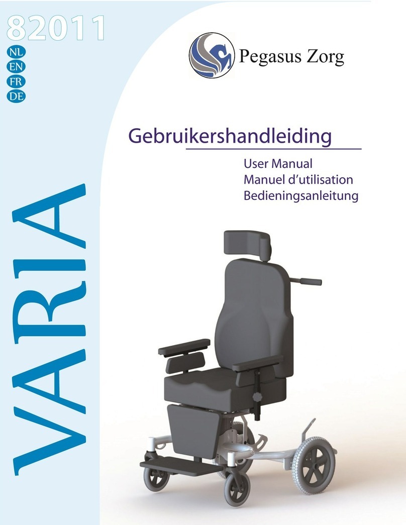
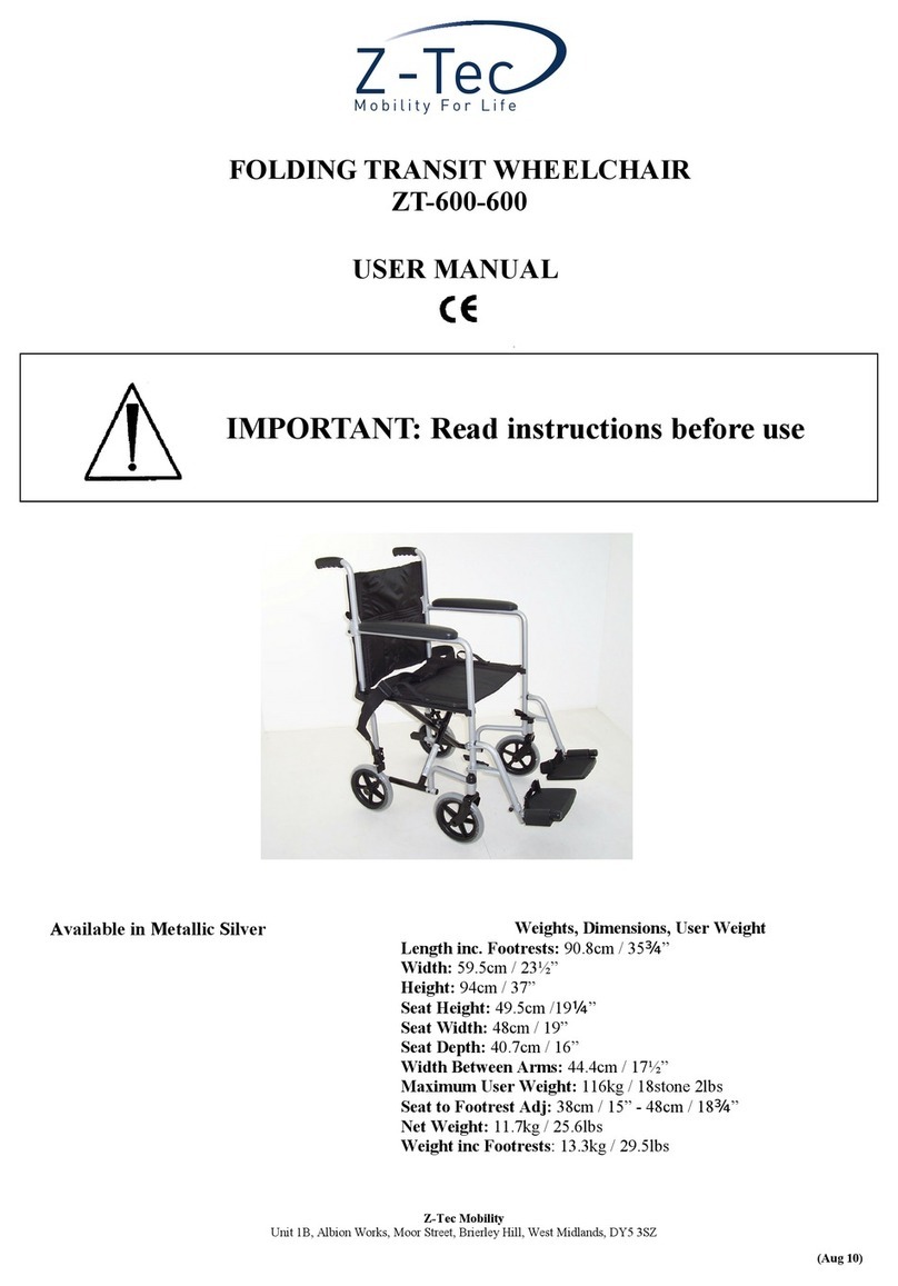
Foldawheel PW-4 4Q Series User manual

V3.0
PW-4x4Q
User Manual

01
TABLE OF CONTENTS
Title Page
Introduction 02
Operation 03 - 04
Parts Introduction 04
Controller Introduction 05 - 08
Gyro System Controller Introduction 09
Adjustment 10 - 12
Charging The Battery 13
Care and Maintenance 14 - 18
Warranty 18
Specification Back Cover

02
The electric wheelchair you have purchased combines the high technology of
optics electrics and machine. Our patended gyro system will adjust your
body centre of gravity to the same level as the terrain. Our electric
wheelchair also can climb up to 30 degree. It’s safe, comfort, and styling.
We are confident that our electric wheelchair will offer you the most convenience
indoor, public location, open space ect.
Read and follow all instructions, and notes in this manual before attempting to
operate your power wheechair for the initial driving. Failure to follow the
instructions in this manual can lead to personal injury or damage to the power
chair including voiding the warranty.
By accepting delivery of this product, you promise that your will not change,
alter, or modify this product or remove of render inoperable or unsafe andy
guards, or other safety features of this product: fail, reuse, or neglect to install
any retrofit kits from time to time provided by PW-4x4Q to enchance or preserve
the safe use of this product.
We would like to hear your comments, and suggestions about our product.We
would also like to know your opinion about the safety and reliability of our power
wheelchair and the service you received from our authorized agent. Please send
us E-mail and tell us your feedbacks.

03
The basic requirement of user:
Safety Instructions:
1. The user must have ability of both physical and metal to use the power chair
safely. User who have vision or mental retardation, please consult the doctor
before using the wheelchair
2. Users should maintain their balance and be able to withstand bumpy caves and
raised driveways. When the strength of the torso muscles is insufficient, they
should consider carrying a seat belt or using a suitable body to receive the system,
such as back-packed sheets, body wrapping paper, etc.
3. User with neck pain or stiff neck, that unable to turn their head back to when
attempting to drive backward, should install a rearview mirror.
4. Users must have sufficient knowledge of electric wheelchair, and have the
confidence to drive by themselves, to cross and overcome rough roads, before
using the electric wheelchair to move indoors by themselves.
1. Before exempting, please read and follow all instructions and precautions
in this manual before operating the power wheechair
2. This electric wheelchair is a monopoly product, please do not renovate other
usage.
3. Before formally use, please practice and open the space to familiarize yourself
with all features.
4. In case of danger, please do not use your mobile phone, laptops or other
radio transmitters while driving an electric wheelchair
5. Do not drive your wheelchair outdoor under any bad weather (rain, snow, thick fog,
strong wind, etc.)
6. While going up or going down stairs or slope, please operated at slow speed
for safety purpose.
7. When doing a 360° rotation, the wheelchair has to be drive in low speed to
protect the motor, reduce noise and prevent component damage
8. The controller or electric wheelchair is a key part of the whole body. Please do not
try to open it for repair, or try other operations to change it, otherwise it will
damage the controller and invalidate the maintenance. The surface of the
controller should be cleaned with a soft dry cloth. It is absolutely forbidden to use
the controller under the conditions of overheating, overload and extreme humidity.

04
9. Do not try to open, repair or replace the motor, otherwise it will damage the motor
and invalidate the maintenance. It is absolutely forbidden to enter the water. When
the electric wheelchair crosses 100 mm, the motor can be soaked; it will cause
permanent damage to the motor.
Parts Introduction Headrest
Safety Belt
Armrest
Turn Signal Light
Rear Wheel
Footrest
Front Light
Gyro System
Controller
Main
Controller
Front Wheel
Rear Light
Tool Kits
Charger
Fifth Wheel
Passenger Step
Backrest Folding
Lever
Armrest Height
Adjustment Knob

05
Increase speed : Turn the Power Button to the right to
increase the speed.
Decrease speed : Turn the Power Button to the left to
decrease the speed.
Controller Introduction
1. Battery Gauge
2. Speed Indicator
3. Power Button
4. Fifth Wheel Selection Button
5. Mode Indicator LED
6. Light / Right Signal Light Button
7. Horn Button
8. Joystick
9. Driving Mode Selection Button
10. Hazard Light/ Left Signal Light
Button
Main Controller
Speed Adjustment
Press the orange arrow button (up/down) the LED light
in the middle will change to orange color, indicate that
you are controlling the fifth wheel.
Tilt the joystick backward to lower down the fifth wheel.
When the motor sounds stop, meaning the wheel is
fully lowered down.
Tilt the joystick forward to raise the fifth wheel. Once
the motor sounds is stop, the wheel is back to the
normal position.
Controlling The Fifth Wheel
Min. Speed
Normal Mode Controlling
Fifth Wheel
Max. Speed
1
2
3
4
5
6
7
8
9
10

06
Using the Joystick
Direction Control- Driving
By default, when the joystick is deflected from the neutral
position, the wheelchair will move in the same direction as
the joystick.
Speed Control
The speed of the drive is proportional to the joystick deflec-
tion, so that the further the joystick is moved from the neutral
position, the faster the drive will travel.
Stopping
To stop driving, either pull the joystick back to the neutral
position, or release the joystick and it will automatically return
to the neutral postion.
Hazard Lights
To switch on the hazard lights, press Hazard Light Button
once, both Hazard Lights Button & Light Button will start
flashing, indicate that the hazard light is on.
To switch off the hazard lights, press Hazard Lights
Button or Light Button once.(P1)
Lights
Press and hold the Light Button, green light will appear
on the the button indicate that the front & rear light is on,
press the same button again to turn the light off.(P2)
Signal Lights
Press and hold the Left or Right Signal Button, the button
will flash accordingly with the signal light for 8 times, then
it will turn off automatically. (P2,P3)
P2
P3
P1

07
The Status Indicator
Battery Gauge
The battery gauge comprises five different LEDs (1x red, 2x amber,
2x green), situated above the remote module’s horn button.
The number of LEDs lit depends on the status of the battery.
The battery gauge LEDs are also used to display charging
information.
High Voltage Warning
A high voltage warning is indicated by all LEDs on, and the green
LEDs flashing. This occurs when the battery voltage level has risen
above the high voltage warning set-point.
Low Voltage Warning
A low voltage warning is indicated with the left-most LED flashing.
This occurs when the battery voltage level has decreased below its
low voltage warning set-point.
Cut-off Voltage
When the battery voltage decreases below the battery cut-off voltage:
- The status indicator will flash
- The first (red) LED will flash on the battery gauge
- The horn will sound once every 10 secends
The status indicator is located underneath the power button.
When the system is not powered up, the status indicator is not lit.
When the system is powered up, and there are no faults with the
system, the status indicator will be lit green.
If, when powered up, there is s fault with the system, then the
status indicator will flash red. The number flashes will indicate the
type of error.

08
Using The Lock Function
To unlock the system, and unlock sequence must be performed by
the user within in a specific time frame. If the sequence is not
performed correctly, within the ime frame, the system will remain
locked and the system will power down again.
To power down and lock the system, press and hold the power
button for 4 seconds.(P4)
When the entering the locked state, the battery gauge will indicate
the transition by flashing LEDs 1, 3, and 5 ( Far left, middle, and far
right) 3 times.(P5)
To power up and unlock the system, press the power button once,
and then, press the horn button twice(P6)- the horn button must be
pressed twice within 10 seconds of pressing the power button.
If the user implements the unlock sequence incorrectly, or the
power button is pressed again before the unlock sequence is
complete, the system will return to the locked state.
During an unlock attempt, the battery gauge will indicate the system
is in a locked state by flashing LEDs 1, 3 and 5 ( far left, middle ,
and far right) until either the system is powered off, unlocked, or the
Sequence Timeout is reached.
The Lock Function is used, primarily to restrict who can use the system, but also can
help prevent unintentional use of the controls for when the system is not required for
any length of time.
When a system is locked ( see below). The system is powered down, and the user
contrals are not responsive. If the power button is pressed when the system is locked,
the locked status is displayed to the user by the battery gauge.
P4
P5
P6

09
OFF
The gyro system is offline, do not turn ON the gyro system
when driving on a horizontal level. (P7)
ON
Press the “ON” button, green light will appear. Gyro
system will automatically adjust to horizontal level when
climbing up stairs or slopes.(P8)
RST
During ascending or descending from the slopes or stairs,
when the seat has reach the maximum angle, it will stop
adjusting the angle and green light will went out. Press the
button to “OFF” and wait for 2 seconds, then click on the
“RST” button. Red light will appear indicate that the gyro
system will be reset, the seat will operate normally. (P9)
Manual Dial
Press the “ON” button, and then press the red button, turn
the dial at the bottom to adjust the seat angle manually.
Only adjust the angle when the wheelchair is static,
adjusting the angle during dynamic will endanger the user
of falling from the wheelchair.(P10,11)
The black line on the dial facing downward indicate the
seat is in neutral angle.
Gyro System Controller Introduction
P10
P7
P8
P9
P11

10
P12
P14
P16 P17
P13
P15
Adjustment
Headrest Height Adjustment
Armrest Height & Width Adjustment
To adjust the height of the headrest, push the button located on the bottom
left of the headrest and adjust the desire height.
Then release the bottom to secure the headrest.(P12,13)
Turn the knob anti-clockwise and pull to
loosen the armrest and adjust the height.
Once adjusted, relese the dial and turn the
knob clockwise to secure the armrest.(P14,15)
The armrest wide adjustment knob
located behind the backrest. Turn
anti-clockwise to loosen it, then pull the
armrest outwards to the widthe desire
and turn the knob clockwise to tighten it.
(P16,17)

11
P18 P19
P20 P21
1. Pull out the pins out from the iron stick.(P18)
2. Take out the iron stick, and the footrest can be taken out.(P19)
3. There are 3 level to adjust, choose the desire height and put back the
iron stick.(P20)
4. Put back the pins to secure the iron stick from slipping out. (P21)
Headrest Height Adjustment

12
P22 P23 P24
P25 P26
1. Fastern the seat belt. (P22)
2. Loosen the straps on the shoulder, then pull to tighten the strap. (P23.24)
3. Same with the waist straps, loosen it and then pull to tighten it.(P.25,26)
WARNING! Do not over tighten the straps, make sure that after tightening
the belt, user still ablt to breath smoothly
Seat Belt Adjustment

1. There is an arrow on the connector, make sure it it always facing upwards
when you are connecting to the controller (P27,28)
2. After connected, switch on the power socket and the wheelchair will start .
charging
LED Indication
13
Charging The Battery
P28
P27
P29
State
Stand by
Precharge
Constant
CurrentCharge
Constant Voltage
Current Limiting
Charge Completion
(stand by)
Trickle Charge
Float Charge
LED 1
(red) LED 2
Off Red
Red
Red
Red
Green
Green
Red(flashing)On
On
On
On
On
Off
The input voltage of the charger will be pre-adjusted to suit
user’s country voltage before it is sent to customer.
User can switch the input voltage to 110V by using a long
thin stick.

14
The electric wheelchair is a sophisticated mobility vehicle. Like any motorized
vehicle, it requires routine maintenance checks.
You can perform some of these checks, but others require assistance from an
authorized provider. Preventive maintenance is very important. If you follow the
maintenance checks in this section as scheduled, you can help ensure that your
wheelchair gives you years of trouble-free operation. If you have any doubt as to
your wheelchair’s care or operation, contact an authorized provider.
WARNING! Direct of prolonged exposure to water or dampness could cause the
electric wheelchair to malfunction electronically and mechanically. Water can
cause electrical components to corrode and the chair’s frame to rust. Electric
wheelchair should be examined periodically for signs of corrosion caused by
water exposure, bodily fluids exposure, or incontinence. Damaged components
should be replaced or treated immediately.
What should you do when your electric wheelchair touched water?
1.Dry your electric wheelchair as thoroughly as possible with towel.
2.Allow your electric wheelchair to sit in a warm, dry place for 12 hours to allow
unseen water to evaporate.
3.Check the joystick operation and the brakes before using your electric wheel
chair again
4.If any inconsistencies are found, take your electric wheelchair to your authorized
provider. Electric wheelchair that is frequently exposed to sources of water,
such as incontinence, should be inspected often for corrosion and electronic
components may need to be replaced frequently.
Temperature
Some of the parts of your electric wheelchair are susceptible to extreme changes
in temperature. Always keep your electric wheelchair between the temperatures of
-20°C and 50°C.
In extremely cold temperatures the batteries may freeze. The specific temperature
at which they freeze depends on a number of factors, such as battery change,
usage, and composition of the batteries.
Temperature about 50°C may cause your electric wheelchair to operate at a
reduced speed. This reduced speed is a safety feature built into the controller that
helps prevent damage to the motor and other electrical components.
Care and Maintenance

15
General Guidelines
Avoid knocking or bumping the controller, especially the joystick. Avoid prolonged
exposure of your chair to extreme conditions, such as heat, cold, or moisture.
Keep the controller clean
Check all connectors to ensure that they are all tight and secured properly. WARN-
ING! Even though the electric wheelchair has passed the necessary testing require-
ments for ingress of liquids, you should keep electrical connections away from
sources of dampness, including direct exposure to water or bodily fluids and inconti-
nence. Check electrical components frequently for signs of corrosion and replace as
necessary.
Daily Checks
With the controller turned off, check the joystick. Make sure it is not bent or damaged
and that It returns to the neutral position when you release it, Check the rubber boot
around the base of the joystick for damage. Visually inspect the boot. Do not handle
or try to repair it, See an authorized provider if there is a problem.
Visually inspect the controller cable. Make sure that it is not frayed, cut, or has any
wires exposed. See an authorized provider if there is a problem.
Check for flat spots on solid tires. Flat spots could adversely affect stability.
Weekly Checks
Disconnect and inspect the controller from the power base. If there is any corrosion,
contact and authorized provider if necessary.
Ensure that all parts of the controller system are securely fastened to your electric
wheelchair.
Calibrate the joystick if a noticeable difference in performance is detected or if the
joystick does not operate properly.
To calibrate the joystick, power off the unit, place the joystick in the neutral position,
and power the unit back on. .If a problem still exists with your joystick’s performance,
contact an authorized provider.
Check the brakes. This test should be carried out on a level surface with at least 3
feet (1 meter) of clearance around your Z-Chair.
Check the brakes.
1. Turn on the controller and turn down the speed level of your electric wheelchair.
2. After one second, check the battery condition meter. Make sure that it remains on.
3. Slowly push the joystick forward until you hear the electric brakes click.
Immediately release the joystick. You must be able to hear each electrical brake
operating within a few seconds of joystick movement. Repeat this test three times,
pushing the joystick backwards, then left, and then right.

16
Monthly Checks
Check for drive tire wear. See an authorized provider to repair. Keep your electric
wheelchair clean and free of foreign material, such as mud, dirt, hair, food, drink etc.
Yearly Checks
Take your electric wheelchair to an authorized provider for yearly maintenance,
especially if you use your chair on a regular basis. This helps ensure that your
electric wheelchair is functioning properly and helps prevent future complications.
Storage
Your electric wheelchair should be stored in a dry place, free from temperature
extremes. When storing, disconnect the batteries from the wheelchair.
WARNING! If you fail to store the electric wheelchair properly, the frame can rust
and the electronics can be damaged.
Batteries that are regularly an deeply discharged, infrequently charged, stored in
extreme temperatures or stored without a full charge may be permanently damaged,
causing unreliable performance and limited service life. It is recommended that you
charge the batteries periodically throughout periods of prolonged storage to ensure
proper performance.
You may wish to place several boards under the frame of your electric wheelchair to
raise it off of the ground during periods of prolonged storage. This take the weigh off
of the tires and reduces the possibility of flat spots developing on the areas of the
tires contacting the ground.
Cleaning and Disinfection
Use a damp cloth and mild, non-abrasive cleanse to clean the plastic and metal
parts of your electric wheelchair. Avoid using products that may scratch the surface
of your electric wheelchair. If necessary, clean your product with and approved
disinfectant. Make sure the disinfectant is safe for use on your product before
application.
WARNING! Never use any chemicals to clean a seat, as they may cause the seat to
become crack, Use soapy water and dry the seat thoroughly.

17
Wheelchair Replacement
If your Wheelchair is equipped with a solid tire insert, then you must replace the
whole wheel assembly; If your wheelchair is equipped with a beach tire, which
maximum charge pressure or pressure range is 2Kpa. When you replace the beach
tire to solid tire, you must exchange the whole wheel assembly. Replacement wheel
assemblies are readily available through an authorized provider.
WARNING! Be sure that the controller’s power is turned off and the electric wheel-
chair is not in freewheel mode before performing this procedure.
WARNING! When changing a tire, remove only the center lug nut and washer then
remove the wheel.
Do as the following steps:
1. Turn off the power to the controller.
2. Set the electric wheelchair up on blocks.
3. Remove the drive wheel nut and washer from the axle.
4. Pull the wheel off the axle.
5. Side the new wheel back onto the shaft. Make sure that the key is in the axle slot.
6. Reinstall the drive wheel nut and washer onto the axle and tighten.
7. Remove the electric wheelchair from the blocks.
Battery Replacement
A battery wiring diagram is printed on a decal located on the front battery tray.
WARNING! Battery posts, terminals, and related accessories contain lead and lead
compounds. Wear goggles and gloves when handling batteries and wash hands after
handling.
WARNING! Do not mix or match new and old batteries. If you encounter a situation
where one battery needs to be replaced, the replace both batteries.
Breakdown overhaul guide
Before the electric wheelchair is asked to maintain, please refer or check following
table, in order to find possible reason caused matters. Some simple check and mix
adjustment you operate can solve the problem and restore normal operation. If you
have questions about some key check factors, or the repairing method showed in
table cannot solve the problems, please contact an authorized provider.

18
PW-4x4Q warranty start from the date of purchase, this products will be
free from defects in material workmanship.
We will repair or replace this product or any component of the product
found to be defective during the warranty period. Replacement will be
made with a new remanufactured product or component. DO NOT
attempt to repair or adjust any electrical or mechanical function on this
product. Doing so will void this warranty.
This warranty does not cover normal wear of parts or damage resulting
from any of the following : negligent use or misuse of the product, normal
wear and tear, use contrary to the operating instructions, disassembly,
repair or alteration representative. Further, the warranty does not cover
water or fire damage.
Warranty
Period (year)
Frame
5 2 1 1
Battery Charger
Motor &
Controller

Net Weight 143 kg (314.5 lb)
Opened Size (L X W X H)
Seat Width Front and Back
Seat Depth
Armrest Length
Max Weight Capacity
Ground Clearence
Slope Limitation
Max Step Height Capability
Folded Size
(Backrest & Footrest) (L X W X H)
107 cm x 75 cm x 91cm (42" x 29.5" x 35.8")
120 cm x 75 cm x 106.5cm (47.2" x 29.5" x 42")
50.8 cm , 46 cm (20", 18")
49 cm (19.2")
50 cm to 59cm(19.6", 23.2")
49cm (19.2")
47cm (18.5")
63cm (24.8") , 61cm (24")
34 to 43cm (13"~16.9")
42.5cm (16.7")
Armrest to Armrest Width (
adjustable)
Backrest Width
Seat Height (Front & Back)
Footrest to Seat Height(adjustable)
Front Wheel Diameter
7cm (2.7")
39cm (15.5")
Rear Wheel Diameter 39cm (15.5")
150kg (330.7lb)
Turning Radius 49 cm (19.2”)
6.5cm (2.5" )
30°
12 cm (4.7")
Battery Type 50AH24V X 1 units
Charging Time 8hrs
Travel Distance (Full Charge) 20~30 km
Motor Type Driving Motor - 750W x 2 units
Level Rack Motor - 300W x 1 units
Travel Distance (Full Charge)
Speed Limit
20~30 km
7.5 km/hr (4.7miles/hr)
Travel Distance (Full Charge)
Speed Limit
20~30 km
7.5 km/hr (4.7miles/hr)
Armrest Width
Backrest Height w/o headrest
Specification
Wheelchair88 Ltd
wheelchair88.com
+60-3-3318 3133
Advanced Mobility Technology
@WheelChair88
Table of contents
Other Foldawheel Wheelchair manuals


