Innov Interlude 500 User manual

User Manual
Interlude 500
Do not use this device and its accessories without reading this manual in full.
Illustrations are for information purposes only.

Table of content
GENERAL................................................................................................................. 4
Symbols............................................................................................................... 4
On the device labels........................................................................................ 4
In this manual.................................................................................................. 5
Abbreviations.................................................................................................. 5
Intended use ........................................................................................................ 6
Illustration of the device ..................................................................................... 8
Characteristics..................................................................................................... 9
Optional features............................................................................................................. 9
Intended Accessories ...................................................................................................... 9
Mechanical specifications................................................................................... 9
Certifications..................................................................................................... 10
Electrical specifications .................................................................................... 10
Storage and handling......................................................................................... 10
INSTALLATION.................................................................................................... 11
Powering the device.......................................................................................... 11
Verification before putting into service............................................................ 12
Positioning in the operating environment......................................................... 13
OPERATING INSTRUCTIONS........................................................................... 15
Electrical functions of the bed .......................................................................... 15
Moving the device............................................................................................. 18
Side rails............................................................................................................ 19
Angle indicators................................................................................................ 20
Length extension of the platform...................................................................... 20
Width extension of the platform....................................................................... 22
Head and foot boards........................................................................................ 23
Adjustment of the foot angle section................................................................ 24
IV poles receptacle............................................................................................ 24
Drainage bag receptacle.................................................................................... 25
Attaching restraint straps .................................................................................. 26
Installation of the trapeze bar (optional)........................................................... 27
Traction frame receptacle ................................................................................. 28
Mechanical CPR fonction................................................................................. 29
Integrated scale (option) ................................................................................... 30
Bed exit detection system (option) ................................................................... 33
System calibration......................................................................................... 33
Buttons identification.................................................................................... 33
Bed exit detection system utilisation ............................................................ 34
Alarm options................................................................................................ 35
Connection options to the nurse call system................................................. 35
Caution.......................................................................................................... 36
Maintenance ............................................................................................................ 37

Cleaning............................................................................................................ 37
Preventive maintenance .................................................................................... 38
Disposal of the device at end of life.................................................................. 39
Troubleshooting Guide ..................................................................................... 40
Verifications.................................................................................................. 40
Explanation of acoustical signals.................................................................. 41
Troubleshooting after a fatal error................................................................ 42
WARRANTY AND RETURN POLICY ..............................................................43
Limited warranty............................................................................................... 43
Return policy..................................................................................................... 44
Non-compliant product................................................................................. 44
Damaged product.......................................................................................... 44
Return product .............................................................................................. 44
REPAIR PROCEDURES....................................................................................... 45
Siderail assembly replacement.......................................................................... 45
Top frame extension replacement..................................................................... 46
Replacement of a wall bumper.......................................................................... 47
Bed caster replacement..................................................................................... 48
Load cell replacement....................................................................................... 51
QLCI replacement............................................................................................. 53
Load cell cable replacement.............................................................................. 56
Scale indicator replacement.............................................................................. 59
Bed exit light replacement................................................................................ 62
Motor replacement of the leg section................................................................ 65
Motor replacement of the backrest section....................................................... 67
Without CPR................................................................................................. 67
With CPR...................................................................................................... 69
High/Low motor replacement........................................................................... 75
Control box replacement................................................................................... 77
Battery replacement .......................................................................................... 79
Power cord replacement.................................................................................... 81
Nurse Call replacement..................................................................................... 83
CPR handle replacement................................................................................... 85
CPR control cable replacement......................................................................... 86
High/low motor lever replacement (foot end) .................................................. 87
High/low motor lever replacement (head end) ................................................. 90

GENERAL
Symbols
On the device labels
Symbol indicating that the mattress dimensions are very
important to respect and to consult the user manual to know
the characteristics.
Symbol illustrating the conditions to respect by the patient
to use the bed safely
Symbol illustrating the patient's maximum weight allowed
on the device.
Symbol illustrating the maximum permissible weight on
the apparatus comprising a patient, the mattress and all
accessories (IV pole, trapeze, traction frame, drainage bag,
etc.)
Symbol indicating to consult the user manual
IPX4
Protection against liquid splashes
Symbol indicating a type B electrical protection

Intended use
This manual has been designed to assist you in using the Interlude 500 bed from Innova
Care Concepts. Be careful to read this document before using the device to ensure a safe
and risk-free usage.
This manual is an integral part of the device and should always be included with the unit
during the sale or transfer. It must be always accessible for medical personnel
and maintenance personnel.
Domain: This device has been designed to be used in a medical care environment such as
a hospital or other medical infrastructure, where medical surveillance is required,
where control measures are applied if required and where the bed is used for medical
procedures such as treatment, diagnostic, supervision, to maintain and improve a patient’s
condition. This includes intensive care, ambulatory care, or regular medical care of a
short or long duration. It is not designed for home care. This device should never be
used in the presence of flammable anesthetic gas mixed with air or oxygen or nitrous
oxide.
Applied parts: It is expected that the parts of the device in contact with the patient and
the operator are the head and footboard, the side rails, the interface, the platform as well
as any accessories intended to be used with the device.
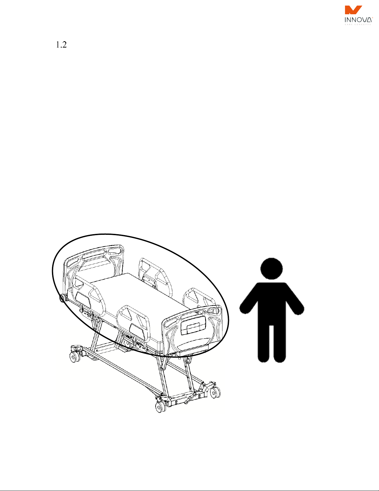
Patient: Patient are intended to use a subset of the device functions using inside controls.
The patient intended to use this device must be an adult with an BMI of 30 or more and a
weight between 250 lb (114 kg) & 1000 lb (454 kg). The bed is not designed for use with
patients with behavioral or mental health issues.

Operator: It is expected that the operator using this device being a health professional
such as a nurse, a doctor, a care giver, etc. This operator must be able to understand and
apply the instructions issued in this manual. It is also expected that the patient can access
some of the functions while in the bed.
Life cycle: This device is designed for a life cycle of 10 years in working condition and in
normal use (see the specifications and conditions of use in the following sections)
Rotec International cannot be held liable for damage or injury caused by negligence or
improper use of its products. Also note that all illustrations contained herein are for
guidance only.
WARNINGS ABOUT THE INTENDED USE
▪The device is not intended for pediatric use or people with a body mass index (BMI)
under 30. Doing so would present serious RISK OF ENTRAPMENT THAT
COULD LEAD TO DEATH.
▪It is imperative to be aware of this manual and to train staff properly before using
the bed and its accessories to prevent ANY INJURY, to both the user and the staff.

19P03-DOC01E REV-3
8
Illustration of the device
Trapeze bar
(option)
Nurse
Control
Upper leg
section
Foot
section
Head
section
Siderails
Thigh
section
Wall
bumpers
Integrated
control in
siderails
Brake
pedal

9
Characteristics
•Adjustable height of the bed
•Inclinable bed frame (Trendelenburg)
•Width extension of the platform
•Foot section and structure expandable in
length
•Angle adjustment of the back section
•Angle adjustment of the thighs section
•Angle adjustment of the foot section
•Mobile device on 12.7cm (5'') diameter
antistatic wheels
•Synchronise brake system with directional
function on wheel
•Traction frame receptacle
•IV pole receptacle
•Drainage bag receptacle
•Restraint strap receptacle
•Trapeze bar receptacle
•Power cable holder
•Composite head and foot boards, removable
without any tools
•Composite half-rail
•Back up battery for temporary autonomy
•Integrated foot mattress retainer
•Integrated angle indicators
•Removable hand control.
•Nurse controls integrated on footboard and
siderails
•Nurse call
•Electrical CPR function
•Mechanical CPR Function
•Auto-contour feature
•Cardiac chair position
•Under bed light
Optional features
•Integrated scale
•Bed exit detection (two zone)
•Additional hand control
•Transportation trolley
Optional features may change the above-mentioned
dimensions.
The dimensions specified herein do not consider
manufacturing tolerances.
Intended Accessories
•Mattress, 9kg (20lb)
•Trapeze bar, 11kg (23lbs)
•IV Pole, 0.5kg (1lbs)
•Drainage bag*
•Traction frame*
•Restraint strap *
* product not available by the device manufacturer.
Mechanical specifications
Maximum load capacity
Patient
Trapeze
IV pole support
Total (SWL)
454kg (1000lb)
77kg (170lbs)
10kg (22lbs)
5 kg per hook
500kg (1100lb)
Device weight
Without accessories
240kg (525lbs)
Overall dimension
Width
Length
102 cm/109 cm
/117 cm/132 cm
(40”/43”/46”/52”)
237 cm /247cm / 257cm
(93 1/8”/97 1/8”/101
1/8”)
Dimension of the mattress support platform
Minimum height
Maximum height
Width
Length
21.6 cm (8 1/2”)
81.3 cm (32”)
88.9cm/ 96.5cm/ 104cm/
119cm
(35”/38”/ 41”/ 47”)
203cm/ 213cm/ 223cm
(80”/ 84”/ 88”)
Maximum inclination angle
Back section
Thighs section
Trendelenburg
65°
34°
±12°
Recommended mattress
Length
Thickness
Width
203cm/ 213cm/ 223cm
(80"/84"/88")
12.7 to 15.2 cm (5 "to
6")
91cm/ 99cm/ 107cm/
122cm
(36”/39”/ 42”/ 48”)

19P03-DOC01E REV-3
10
Certifications
CSA standards
•--------------------------------
•--------------------------------
•--------------------------------
•--------------------------------
•--------------------------------
ANSI/AAMI standards
•--------------------------------
•--------------------------------
•--------------------------------
•--------------------------------
•--------------------------------
Electrical specifications
Classification
Class II
Power
120/230 VAC
Frequency
50/60 Hz
Current Rating
5.8 A
Protection
IPX4
Duty cycle
10% maximum
(2 min. / 18 min.)
Maximum acoustic
sound pressure
Scale accuracy (option)
< 55 dBa
± 2% + 1 kg (2%+ 2 lb).
Storage and handling
Operating environment
Temperature
5 to 40 ˚C
Relative humidity
15% to 95%
(Non-condensing)
Atmospheric
pressure
70kpa to 106kpa
Storage environment
Temperature
–40 to 70 ˚C
Relative humidity
10% to 100%
(Non-condensing)
Atmospheric
pressure
70kpa to 106kpa
WARNINGS ABOUT FEATURES AND SPECIFICATIONS
▪Make sure that the height of the mattress is convenient for entering and exiting the
device easily. Otherwise, it may cay cause a RISK OF FALLING that could lead
to SERIOUS INJURY.
▪Before lowering the mattress completely, make sure there is no body parts of the
patient exceeding or are underneath the mattress to avoid SERIOUS INJURY
AND/OR TO POTENTIAL BREAK on the device.

19P03-DOC01E REV-3
11
INSTALLATION
Powering the device
At all time, the primary voltage on the device can be removed safely by unplugging the
unit's power cable connected to the wall socket for this purpose. Ensure the power cable is
always accessible.
Note that this device is of Class II and that, for this reason, the power plug isn’t grounded.
WARNINGS ABOUT POWER TO THE UNIT
▪Connecting the device to a supply network that has no grounding terminal
increases RISK OF ELECTRIC SHOCK;
▪After accidental and significant spill of liquid on electronic components, cables and
/ or motors the operation of these components may be affected. You should
immediately disconnect the bed and then remove the user from the bed, clean and
inspect the bed by qualified technicians. The bed can be returned to service only if
it has been properly cleaned and inspected. Not following these instructions could
jeopardise the integrity of the device and could lead to SERIOUS INJURY.
▪Make sure the power cable is always at a safe place during the use of the device to
avoid damaging it and causing SERIOUS ELECTROCUTION INJURY.

19P03-DOC01E REV-3
12
Verification before putting into service
The following verifications are required to ensure that no damage occurred during
transport of the bed:
▪(If applicable) Check that the packaging of the device has no apparent damage;
▪(If applicable) Unpack the device from its packaging;
▪Visually inspect if the device appears to be in good condition;
▪Connect the device power cable;
▪Allow the device to be connected for at least 48 consecutive hours;
▪Then verify that each function of the device operates according to the operating
instructions provided in this manual (see section 3);
▪Unplug the power cable and operate the actuators to verify the battery.
Note that the verification of CPR function should be performed with a mattress and a
person adequately leaned otherwise it might not work. If damage or malfunction appear
on the bed, without hesitation contact the Technical Services Department of Rotec
International.
WARNINGS ABOUT VERIFICATION
▪Ensure that the power cables of electrical devices that are nearby do not get caught
in the moving parts of the device. Not doing so could lead to SERIOUS INJURIES
BY ELECTROCUTION.

19P03-DOC01E REV-3
13
Positioning in the operating environment
To install this bed model, place it horizontally at a distance of at least 127 mm (5 inches)
from the wall. In the same manner, check that no object obstructs the end of the feet
section and then apply the brakes (see section 3.2)
It is therefore possible to use the bed without worrying about the risk of contact with the
wall.
127 mm
(5 in.)
FOOT
HEAD

19P03-DOC01E REV-3
14
Installation/Replacement of the mattress
Use a mattress corresponding to the recommended specifications. Ensure that the
platform configuration is matching the mattress. (See Mechanical Specifications)
Lay the mattress on the device and insert it in between the rail guards of the platforms.
Notice that the mattress must be compressed to be inserted. Otherwise, the platform
adjustment is inappropriate for the dimensions of the mattress.
WARNINGS ABOUT FEATURES AND SPECIFICATIONS
▪Use a mattress of the correct size and adapted to the platform size in order to avoid
RISKS OF ENTRAPMENT between the siderails and mattress which can lead to
DEATH.

15
OPERATING INSTRUCTIONS
Electrical functions of the bed
Symbols
Descriptions
Arrow pointing upwards: Allow upward adjustment of the various functions of the
equipment.
Arrow pointing downwards: Allow downward adjustment of the various functions
of the equipment.
Backrest functions: Allow tilting adjustment of the backrest section upwards or
downwards.
Press on the arrow pointing upwards or downwards located next to the symbols to
switch on the motor. Release the control to stop all movement.
Thigh functions: Allow tilting adjustment of the thigh section and raising or
lowering the foot section.
Press on the arrow pointing upwards or downwards located next to the symbols to
switch on the motor. Release the control to stop all movement.
Auto-contour functions: Allow tilting the thigh section and the backrest section and
adjusting the height of the foot section upwards or downwards at the same time.
Press on the arrow pointing upwards or downwards located next to the symbols to
switch on the motor. Release the control to stop all movement.
Bed height functions: Allow the height adjustment upwards or downwards of the
bed.
Press on the arrow pointing upwards or downwards located next to the symbols to
switch on the motor. Release the control to stop all movement.
Note: The buttons situated on the inside of siderails and on the remote control have a
limited range for lowering the bed for safety reasons. To lower the bed to the lowest
height, use the controls on the foot panel.
Trendelenburg functions: Allow tilting the bed so the foot section is lower than the
head section and conversely.
Press on the arrow pointing upwards or downwards located next to the symbols to
switch on the motor. Release the control to stop all movement.
Note: the function stops when the bed is back horizontally.
Locking functions: Allow locking a function of the remote control and of the patient
control from the nurse control at the foot of the bed. Each function can be locked
individually or by group.
Press this button to lock the function displayed nearby. A red indicator will light up
underneath the lock symbol, indicating that the function is locked.

16
Total lock functions: Allow locking all moving functions of the equipment located
on the remote control, the patient control on the side of the bed and at the foot control
of the bed except for the CPR functions.
Press this button for 5 seconds. Red indicators will light up under each of the locked
symbols of the nurse control indicating that the moving functions of the equipment
are locked. To deactivate this function, press again and hold the button for 5 seconds.
Chair position: Allow the bed to be moved in a chair position. This function tilts up
the back and thigh sections upwards, adjust the height of the foot upwards and tilt up
the bed so the foot section is lower than the head section.
Press this button until all functions reach their maximum positions. Release the
control to stop all movement.
Note: The complete operation may take up to 60 sec.
Electric CPR function: Allow the optimum positioning of the bed to apply the
cardiopulmonary resuscitation. This function must be use for this purpose ONLY.
Release the control to stop all movement.
Light function: This function turns on the light located underneath the bed.
Press this button to turn on or off the light.
Nurse call function (optional): This function sends a signal to the nurse’s station.
Press this button to send the signal.
Plug-in indicator light The illuminated indicator light indicates that the bed is
plugged in a wall power outlet.
WARNINGS ABOUT THE USE OF ELECTRICAL FUNCTIONS
▪If the user's physical condition requires it, and that, for his own safety, lock the
movement of the bed functions intended to be used by the patient and place the bed
in the low position, the platforms horizontal and bed rails in the raised position;
▪Ensure that no body part exceed the mattress and that there is nothing interfering
under the platform of the bed before activating the CPR function. SERIOUS
INJURIES may occur if this function is not used properly.
▪CPR function should only be USED IN CASE OF EMERGENCY ONLY. Using
this function for other purposes could lead to SERIOUS INJURIES to the patient
or operator.

17
WARNINGS ABOUT THE USE OF ELECTRICAL FUNCTIONS (CONTINUED)
▪Always position the bed at a reduced height when the patient is sleeping or
unattended to reduce the RISK OF FALLS that could lead to INJURIES.
▪Do not leave a table or other device requiring access under the bed when it is
lowered down because this will cause SERIOUS MECHANICAL DAMAGE.
▪Always make sure no objects or equipment hinders the movement of the movable
parts of the bed before activating a motion controls, such as: patient or staff limbs,
medical equipment, etc. this could result in SERIOUS INJURY AND / OR
DAMAGE TO EQUIPMENT.

19P03-DOC01E REV-3
18
Moving the device
To move the device, it is recommended to raise the bed at least 150mm (6 inches) from
its lowest position in order to facilitate access to the pedal. To operate the system, place
the pedal in one of the following three positions:
DIRECTIONAL
To limit the head right
wheel to move in a straight
line and remove all
restrictions to the other
wheels.
Press on the green side of
the pedals.
NEUTRAL
To remove all restrictions
and allow the bed to move
in any direction:
Place the pedals
horizontally.
BRAKE
To apply the brake and
completely immobilise the
bed:
Press on the red side of the
pedals.
When the bed is heavily loaded, it is recommended to have two persons to move it.
WARNINGS ABOUT THE SYNCHRONISED BRAKE SYSTEM
▪Always apply the brakes after moving the bed or when a patient is on the bed
since not doing so could cause INJURIES to the patient when he or she gets in
and out of bed.
▪Always verify that the brakes are well locked after they are activated by trying to
move the device.

19
Side rails
To lower one side rail,push the lever located underneath the mattress near the mechanism
and move the side rail downwards with a rotating movement. For better security, the side
rail locks after being activated. Press again on the lever and move the half-length side
rail until it stops in the lowest position.
To raise the side rail, pull the side rail upwards by a rotational movement. Then, make sure
that the side rail is completely locked at the highest position by trying to move it sideways.
WARNINGS ABOUT SIDERAILS USE
•When raising the siderails in close position, always make sure that the side rail is
completely locked at the highest position by trying to move it sideways in order to
avoid RISKS OF FALLING.
•The side rails are designed to prevent accidental falls only. They should not be used
to prevent the patient from leaving the bed, to assist the patient to turn over in bed or
as a restraint. Is the responsibility of the operator to use appropriate restraints, and
this in the interest and for the safety of the user;
•Ensure that nothing can impede the movement of the side rails (blankets, patient's
limbs, etc.) before you activate them.
•Unless otherwise medically advised by a professional, leave the side rails up and
locked while the user is sleeping or left without any supervision to avoid RISKS OF
FALLING; also, it is recommended to keep the height of the bed to its lowest in order
to reduce the RISKS OF INJURIES related to falling.
•Make sure the feets are not under the device when lowering the patient surface to its
lowest. When the siderails are open (unlock position), they may come in contact with
the ground and raise a little.

20
Angle indicators
The approximate angle of the back-rest section relative to the ground is approximately
given by the angle indicator fixed underneath the back-rest section. The measurements (in
degrees) is indicated by a small ball following the etched graduation.
Length extension of the platform
* It is recommended to elevate the foot section to the maximum in order to operate the
extension of the platform with ease.
1) Pull the cable located under the foot section;
2) With the other hand, push/pull the foot extension of the structure;
3) Release the cable. The extension will lock automatically to the following mattress
dimensions: 84 in & 88 in (213 cm & 223 cm).
CABLE

21
4) Push the button located to the end of the foot section
5) With the other hand, push/pull the foot extension of the section
6) Release the button. The extension will lock automatically to the following
mattress dimensions: 84 in & 88 in.
WARNING ON LENGTH EXTENSION OF THE PLATFORM
▪Never extend the foot section platform without extending the foot section of the
structure to avoid MECHANICAL BREAK AND/OR INJURIES.
▪After extending the platform, always verify that the length fits the size of the
mattress use to avoid RISKS OF ENTRAPEMENT that could lead to DEATH.
BOUTON
Table of contents
Other Innov Wheelchair manuals
Popular Wheelchair manuals by other brands

Vermeiren
Vermeiren Eclips X4 kids instruction manual

Invacare
Invacare REA Dahlia 30 Service manual

Handicare
Handicare LI2161.121 Series manual

Invacare
Invacare TDX SP Operator and maintenance manual

Livingston Innovations
Livingston Innovations Freedom Trax user manual

Solar Mobility
Solar Mobility liberator Service guid