Foley United ACCU-Pro 670 User manual

1
ACCU-Pro
MODEL 670
SEMI-AUTOMATIC
BEDKNIFE GRINDER
ASSEMBLY
AND
SERVICE
MANUAL
WARNING
You must thoroughly read and understand this
manual before assembling or maintaining the
equipment, paying particular attention to the
Warning & Safety instructions.
6707954(8-01)

2
SAFETY INSTRUCTIONS
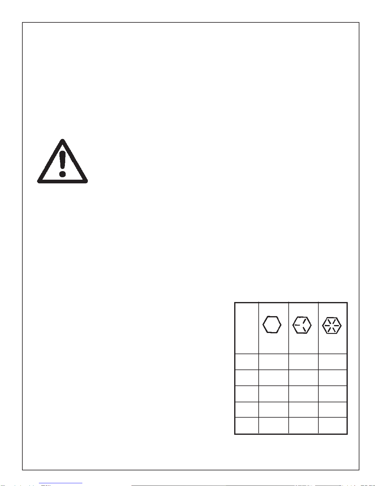
Safety Awareness Symbols
are inserted into this
manual to alert you to possible
Safety Hazards
.
Whenever you see these symbols, follow their
instructions.
The
Caution Symbol
identifies special instructions
or procedures which, if not correctly followed, could
result in damage to or destruction of equipment.
The
Warning Symbol
identifies special instructions
or procedures which, if not strictly observed, could
result in personal injury.
12. DON'T OVERREACH.
Keep proper footing and
balance at all times.
13. MAINTAIN GRINDER WITH CARE. Follow
instructions in Service Manual for lubrication and
preventive maintenance.
14. DISCONNECT POWER BEFORE SERVICING.
15. REDUCE THE RISK OF UNINTENTIONAL
STARTING. Make sure the switch is OFF before
plugging in the Grinder.
16. USE RECOMMENDED ACCESSORIES. Consult
the manual for recommended accessories. Using
improper accessories may cause risk of personal
injury.
17. CHECK DAMAGED PARTS. A guard or other
part that is damaged or will not perform its
intended function should be properly repaired or
replaced.
18. KNOW YOUR EQUIPMENT. Read this manual
carefully. Learn its application and limitations as
well as specific potential hazards.
19. KEEP ALL SAFETY DECALS CLEAN AND
LEGIBLE. If safety decals become damaged or
illegible for any reason, replace immediately. Refer
to replacement parts illustrations in Service
Manual for the proper location and part numbers
of safety decals.
20. DO NOT OPERATE THE GRINDER WHEN
UNDER THE INFLUENCE OF DRUGS,
ALCOHOL, OR MEDICATION
1. KEEP GUARDS IN PLACE and in working
order.
2. REMOVE WRENCHES AND OTHER
TOOLS.
3. KEEP WORK AREA CLEAN.
4. DON'T USE IN DANGEROUS ENVIRONMENT
.
Don't use Grinder in damp or wet locations, or
expose it to rain. Keep work area well lighted.
5. KEEP ALL VISITORS AWAY
.
All visitors
should be kept a safe distance from work area.
6. MAKE WORK AREA CHILD-PROOF with
padlocks or master switches.
7. DON'T FORCE THE GRINDER. It will do the job
better and safer if used as specified in this
manual.
8. USE THE RIGHT TOOL. Don't force the Grinder
or an attachment to do a job for which it was not
designed.
9. WEAR PROPER APPAREL.
Wear no loose
clothing, gloves, neckties, or jewelry which may
get caught in moving parts. Nonslip footwear is
recommended. Wearprotectivehaircoveringto
contain long hair.
10. ALWAYS USE SAFETY GLASSES
.
11. SECURE YOUR WORK. Make certain that the
bedknife is securely fastened with the
electromagnets provided before operating.

3
SAFETY INSTRUCTIONS
DON'T
1. DON'T use a cracked wheel or one that HAS
BEEN DROPPED or has become damaged.
2. DON'T FORCE a wheel onto the machine OR
ALTER the size of the mounting hole - if
wheel won't fit the machine, get one that will.
3. DON'T ever EXCEED MAXIMUM
OPERATING SPEED established for
the wheel.
4. DON'T use mounting flanges on which the
bearing surfaces ARE NOT CLEAN, FLAT
AND FREE OF BURNS.
5. DON'T TIGHTEN the mounting nut
EXCESSIVELY.
6. DON'T grind on the SIDE OF THE WHEEL
(see Safety Code B7.2 for exception).
7. DON'T start the machine until the WHEEL
GUARD IS IN PLACE.
8. DON'T JAM work into the wheel.
9. DON'T STAND DIRECTLY IN FRONT of a
grinding wheel whenever a grinder is started.
10. DON'T FORCE GRINDING so that motor
slows noticeably or work gets hot.
AVOID INHALATION OF DUST generated by grinding and cutting operations.
Exposure to dust may cause respiratory ailments. Use approved NIOSH or
MSHA respirators, safety glasses or face shields, and protective clothing.
Provide adequate ventilation to eliminate dust, or to maintain dust level
below the Threshold Limit Value for nuisance dust as classified by OSHA.
IMPROPER USE OF GRINDING WHEEL MAY CAUSE
BREAKAGE AND SERIOUS INJURY.
Grinding is a safe operation if the few basic rules listed below are followed.
These rules are based on material contained in the ANSI B7.1 Safety Code for
"Use, Care and Protection of Abrasive Wheels". For your safety, we suggest
you benefit from the experience of others and carefully follow these rules.
DO
1. DO always HANDLE AND STORE wheels in a
CAREFUL manner.
2. DO VISUALLY INSPECT all wheels before
mounting for possible damage.
3. DO CHECK MACHINE SPEED against the
established maximum safe operating speed
marked on wheel.
4. DO CHECK MOUNTING FLANGES for equal
and correct diameter.
5. DO USE MOUNTING BLOTTERS when
supplied with wheels.
6. DO be sure WORK REST is properly adjusted.
7. DO always USE A SAFETY GUARD
COVERING at least one-half of the grinding
wheel.
8. DO allow NEWLY MOUNTED WHEELS to run
at operating speed, with guard in place, for at
least one minute before grinding.
9. DO always WEAR SAFETY GLASSES or some
type of eye protection when grinding.
10.DO TURN OFF COOLANT before stopping to
avoid creating an out-of-balance condition.

4
This machine is intended for grinding the bedknife from a reel mowing
unit ONLY. Any use other than this may cause personal injury and void
the warranty.
This machine is intended for indoor use only.
To assure the quality and safety of your machine and to maintain the
warranty, you MUST use original equipment manufactures replacement
parts and have any repair work done by a qualified professional.
ALL operators of this equipment must be thoroughly trained BEFORE
operating the equipment.
Do not use compressed air to clean grinding dust from the machine. This
dust can cause personal injury as well as damage to the grinder. Do not use a
power washer to clean the machine.
CONTENTS
Assembly...................................................................................................... Page 6 - 12
Maintenance ................................................................................................ Page 13 - 15
Adjustments ................................................................................................. Page 16-23
Troubleshooting ........................................................................................... Page 24-33
Electrical Schematic..................................................................................... Page 34
Parts List. ..................................................................................................... Page 35-48
SPECIFICATIONS
Electrical Requirements ............................................................ 115V 50/60 Hz, 15-amp circuit
Net Weight ....................................................................................................... 780 lbs [354 kg]
Shipping Weight............................................................................................... 920 lbs [417 kg]
Maximum Grinding Length................................................................................34 in. [863 mm]
SoundLevel.....................................................................................................Lessthan75Dba
The grinder is equipped with a low voltage relay which
is factory preset at 100 VAC. If the power supply line
does not deliver 100 VAC power under load, the relay
will open and trip out the starter. If this occurs, your
power supply line is inadequate and must be correct
before proceeding further with the grinder.
ADJUSTMENT OF THE LOW VOLTAGE RE-
LAY MAY CAUSE ELECTRICAL COMPONENT
FAILURE. ADJUSTMENT OF THE LOW
VOLTAGE RELAY WILL VOID ALL
ELECTRICAL COMPONENT WARRANTY.
Low Voltage Relay
5
SKILL AND TRAINING REQUIRED FOR SERVICING
This Service Manual is designed for technicians who have the neces-
sary mechanical and electrical knowledge and skills to reliably test
and repair the ACCU-Pro Bedknife Grinder. For those without that
background, service can be arranged through a local distributor.
This Manual presumes that you are already familiar with the normal
operation of the Grinder. If not, you should read the Operators
Manual, or do the servicing in conjunction with someone who is
familiar with its operation.
PERSONS WITHOUT THE NECESSARY
KNOWLEDGE AND SKILLS SHOULD NOT
REMOVE THE CONTROL BOX COVER OR
ATTEMPT ANY INTERNAL
TROUBLESHOOTING, ADJUSTMENTS, OR
PARTS REPLACEMENT!
If you have questions not answered in this manual, please call your
distributor. They will contact the manufacturer if necessary.
TORQUE REQUIREMENTS
Throughout this manual we refer to torque requirements as
"firmly tighten" or the like. For more specific torque values, refer
to the information below.
Bolts Going into a Nut, or Into a Thread Hole in Steel.
Refer to table at the right.
Bolts Going into a Thread Hole in Aluminum.
Use the Grade 2 values in the table at the right.
Socket-Head Screws
Use the Grade 8 values in the table at the right.
Machine Screw
No. 6 Screws: 11in.-lbs [0.125 kg-m]
No. 8 Screws: 20 in.-lbs [0.23 kg-m]
No. 10 Screws: 32 in.-lbs [0.37kg-m]
GRADE 2 GRADE 5 GRADE 8
SMOOTH 3 MARKS 6 MARKS
HEAD on HEAD on HEAD
1/4 In. 6 ft-lbs 9 ft-lbs 13 ft-lbs
thread (0.8 kg-m) (1.25 kg-m) (1.8 kg-m)
5/16 In. 11 ft-lbs 18 ft-lbs 28 ft-lbs
thread (1.5 kg-m) (2.5 kg-m) (3.9 kg-m)
3/8 In. 19 ft-lbs 31 ft-lbs 46 ft-lbs
thread (2.6 kg-m) (4.3 kg-m) (6.4 kg-m)
7/16 In. 30 ft-lbs 50 ft-lbs 75 ft-lbs
thread (4.1 kg-m) (6.9 kg-m) (10.4 kg-m)
1/2 In. 45 ft-lbs 75 ft-lbs 115 ft-lbs
thread (6.2 kg-m) (10.4 kg-m) (15.9 kg-m)

6
ASSEMBLY INSTRUCTIONS
FIG. 2
FIG. 1
NOTE: For clarity, the Grinder is shown on the following
pages without the optional carriage bellows installed.
UNPACK THE CARTONS
NOTE: Before you install the machine, read the following
assembly procedure completely. Then study "Getting to
Know Your Bedknife Grinder" in the Operators Manual.
Use care when unpacking. Double-check the packing
cartons for any miscellaneous items before discarding.
Inspect all items for shipping damage as they are
removed from the shipping containers. If you find any
damage, notify the carrier's claims agent and do not
proceed further until the damage has been inspected by
the agent. Refer also to the "Shipping and Receiving
Instructions" packed with the unit.
Remove the Coolant Tank carton from under the machine.
Remove the control box from under the machine. Be
careful of the electrical wiring which was preconnected at
the factory.
Install the Control Box
Attach the control box to the right front end of the
machine, using the two 3/8-16 x 5/8" hex-head bolts, and
two lock washers provided. See FIG. 1. The fasteners
are shipped in an envelope inside the control box carton.
Remove the Grinder from the Pallet
To remove the Grinder from the wood pallet:
1. Unbolt the brackets that hold each end of the
Grinder legs to the bottom of the pallet.
2. The Grinder's four leveling feet (FIG. 2) are seated in
countersunk holes in the pallet. Lift one end of the
machine until both feet are out of their holes.
3. Prop this first end up with sturdy boards or other
supports so the feet remain out of their holes, then lift
the other end and remove the Grinder from the pallet.
THE GRINDER WEIGHS 780 LBS
[354 KG]. TO LIFT, USE POWER
EQUIPMENT OR GET ADEQUATE
HELP.
Remove the shipping strap that secures the grinding
head and carriage to the left end of the machine during
shipment. Reinstall the wiper plate screw which held the
right end of the strap. Discard the leg screw and the
shipping strap.
7
ASSEMBLY INSTRUCTIONS (Continued)
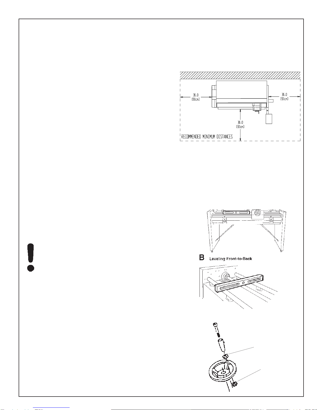
LOCATE AND LEVEL THE GRINDER
Set the Grinder on a level concrete floor, on a single
uncracked slab of concrete.
If the unit must be located near a wall, allow adequate
space for operating and servicing. Refer to FIG. 3 for
recommended and alternate locations near a wall.
Place a level on the front carriage rail near the center of
the machine and check the level from left to right. See
FIG. 4A. Adjust the leveling feet until the machine is level.
Place the level across the front and rear carriage rails near
the left end of the machine. See FIG. 4B. Adjust the two
leveling feet on the left end until the rear rail (the one
closest to the coolant tray) is slightly lower than the front
rail--so any coolant on the carriage, main base, or optional
bellows will drain back into the coolant tray.
Place the level across the front and rear carriage rails near
the right end of the carriage bed. Level the right end in
the same way as the left end. For grinding accuracy, the
two ends must have the identical backward slant within +/-
.01" [.25 mm] so the frame is not twisted.
Recheck the level in both directions. When satisfactory,
tighten the hex jam nuts on the leveling feet securely
against the nuts welded to the bottom of the base. See
FIG. 2. Don't turn the leveling feet when tightening.
Again recheck the level after the nuts are firmly tightened.
FOR GRINDING ACCURACY, THE MACHINE
DOES NOT HAVE TO BE PERFECTLY LEVEL.
HOWEVER, IT IS CRITICAL THAT FRONT-TO-
BACK LEVELING BE IDENTICAL AT BOTH
ENDS OF THE MACHINE.
INSTALL THE SPINNING HANDLES
Install the spinning handle on the horizontal handwheels.
See FIG. 5. Handle parts are packed in an envelope
taped to the wheel.
FIG. 4
FIG. 5
Regular Hex Nut
Lock Nut
ALeveling Side-to-Side
FIG. 3

8
ASSEMBLY INSTRUCTIONS (Continued)
FIG. 7
APPLY POWER
BEFORE YOU APPLY POWER TO THE
GRINDER, REFER TO THE "IMPORTANT
GROUNDING INSTRUCTIONS" ON PAGE 9.
115 Volt Model Only. Plug the control box power cord into a
standard 115V AC 15-amp grounded receptacle. See FIG. 7.
220 Volt Model Only. For 220 Volt Applications order Part
No. 6700951, which includes a 220 to 110 Volt Step Down
Transformer. See Details on page 9.
IT IS RECOMMENDED THAT THIS ACCU-
PRO BEDKNIFE GRINDER HAS ITS OWN
PERMANENT POWER CONNECTION FROM
THE POWER DISTRIBUTION PANEL, WITH
NO OTHER MAJOR POWER DRAW
EQUIPMENT ON THE SAME LINE.
IT IS REQUIRED THAT THE POWER
DELIVERED TO THIS GRINDER IS 115 VAC -
15 AMPS. THE TOLERANCE ON THIS
POWER REQUIREMENT IS +/- 5%.
THEREFORE THE MINIMUM VOLTAGE
REQUIREMENT IS 109VAC WITH 15 AMPS.
VOLTAGE MUST BE CHECKED WITH ALL
EQUIPMENT UNDER LOAD (OPERATING) ON
THE CIRCUIT.
DO NOT OPERATE THIS GRINDER WITH
AN EXTENSION CORD.
The grinder is equipped with a low voltage relay
which is factory preset at 100 VAC. If the power
supply line does not deliver 100 VAC power under
load, the relay will open and trip out the starter. If
this occurs, your power supply line is inadequate
and must be correct before proceeding further with
the grinder.
ADJUSTMENT OF THE LOW
VOLTAGE RELAY MAY CAUSE
ELECTRICAL COMPONENT
FAILURE. ADJUSTMENT OF
THE LOW VOLTAGE RELAY
WILL VOID ALL ELECTRICAL
COMPONENT WARRANTY.
PROPER GROUNDING OF THE RECEP-
TACLE GROUND IN YOUR BUILDING MUST
BE VERIFIED. IMPROPER GROUNDING IN
YOUR BUILDING MAY CAUSE THE GRINDER
TO MALFUNCTION.
FOR 15 AMP RATED LARGE MACHINES
For 0 to 30 Feet from panel to receptacle = Use 14 Ga. Wire.
For 30 to 50 Feet from panel to receptacle = Use 12 Ga. Wire.
For 50 to 80 Feet from panel to receptacle = Use 10 Ga. Wire.
For 80 to 140 Feet from panel to receptacle = Use 8 Ga. Wire.
For 0 to 9 Meters from panel to receptacle = Use 2.5mm Wire.
For 9 to 15 Meters from panel to receptacle = Use 4.0mm Wire.
For 15 to 24 Meters from panel to receptacle = Use 6.0mm Wire.
For 24 to 42 Meters from panel to receptacle = Use 10.0mm Wire.
9
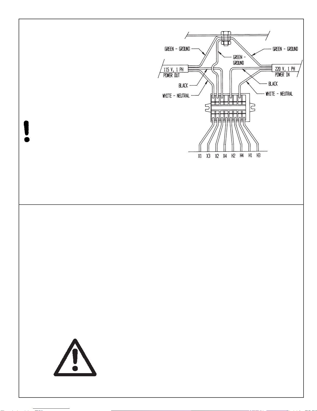
FOR 220 V 50 or 60Hz applications Product No.
6700951 should be ordered.
6700951 includes a 2 KVA 220 Volt Step Down
to 110 volt 50/60 Hz transformer which is
prewired.
The wiring diagram is shown in FIG. 8.
The power cord has no connector. A connector
which is appropriate for your locality and 220 volt,
8 amp application should be installed.
ASSEMBLY INSTRUCTIONS (Continued)
FIG. 8
IMPORTANT GROUNDING INSTRUCTIONS
In case of a malfunction of breakdown, grounding reduces the risk of electrical shock by providing a path
of least resistance for electrical current.
This Grinder has an electrical cord with an equipment grounding conductor and a grounding plug. The
plug must be plugged into a matching outlet that is properly installed and grounded according to all local
or other appropriate electrical codes and ordinances.
Before plugging in the Grinder, make sure it will be connected to a supply circuit protected by a properly-
sized circuit breaker or fuse.
Never modify the plug provided with the machine--if it won't fit the outlet, have a proper outlet and circuit
installed by a qualified electrician.
ALWAYS PROVIDE A PROPER ELECTRICAL GROUND FOR
YOUR MACHINE. AN IMPROPER CONNECTION CAN CAUSE A
DANGEROUS ELECTRICAL SHOCK. IF YOU ARE UNSURE OF
THE PROPER ELECTRICAL GROUNDING PROCEDURE,
CONTACT A QUALIFIED ELECTRICIAN.
Use only a qualified electrician to
complete the installation.
10
ASSEMBLY INSTRUCTIONS (Continued)
INSTALL THE OPTIONAL
CARRIAGE BELLOWS (if ordered)
Optional carriage bellows are available to keep excess
grindings, dirt, etc. out of the carriage assembly. To
install the two bellows:
1. Remove the left and right outside leg panels.
2. Remove the shaft seal on each side of the linear
actuator. See FIG. 9. NOTE: When the bellows are
used, the shafts don't get lubricated and the seals
would run dry. They would then become noisy and
not operate properly.
To remove the seals:
a. Crank the carriage all the way toward the
front (that is, toward the operator's position).
b. Remove the actuator mounting screw on top
of the carriage. See FIG. 9. Then push the
carriage toward the right end of the Grinder.
c. Loosen the two set screws in the bearing
pillow block at each end of the drive shaft.
Loosen the two set screws in the drive
coupling at the right end of the carriage.
d. Turn the actuator release lever clockwise 1/2
turn until the actuator is released from the
shaft. See FIG. 9.
e. Slide the drive shaft out the left end of the
machine.
f. Remove the shaft seals from the actuator -
two screws each.
g. Reinstall the drive shaft. The right end of
the shaft (inside the coupling) should be
1/8 - 1/4" [3 to 6.5 mm] from the end of the
motor shaft. Retighten all set screws.
h. Push the carriage back to the left, and
reattach the actuator with the mounting
screw. See FIG. 9. Turn the actuator
release lever, 1/2 turn.
3. Remove the two rail wiper brackets from each side
of the carriage - two screws each. See FIG. 11.
4. Attach the outer end of each bellows to the Grinder
leg panel. See FIG. 10. Use six bolts, and hex
nuts, at each end. The bolt heads go on the bellows
side of the brackets.
5. Attach the inner end of each bellows to the carriage.
See FIG. 11. Use four L-brackets, (two on each
side of the last bellows fold), six bolts, and two hex
nuts at each end. Nuts are required only for the
lower holes of the L-brackets.
6. Press the bellows down until it snaps onto the
carriage rails.
7. Reattach the left and right outside leg panels.
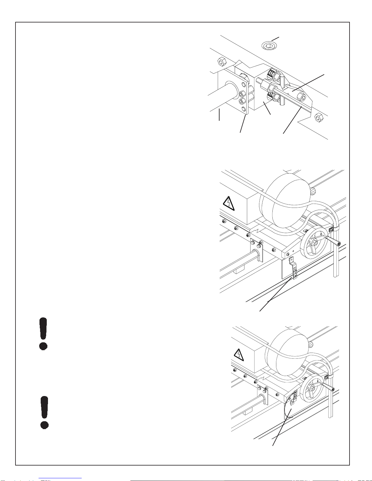
FIG. 9
Actuator Mounting
Screw (under the rubber
splash guard)
Drive Shaft
Actuator Bar Assembly
Linear Actuator
Seal Plate Actuator Release Lever

11
ASSEMBLY INSTRUCTIONS (Continued)
FIG. 12
FIG. 13
INSTALL THE COOLANT TANK
Assemble the Coolant Tank as outlined in the instructions
(Part No. 7467909) in the coolant tank carton.
Center the Tank under the Grinder.
Install the 1" I.D. drain tubing over the barbed end of the
plastic adapter on the coolant tray drain. Cut the tubing to
the proper length to reach about 1-1/2" [40 mm] into the
large opening on top of the Coolant Tank. See FIG. 12.
A pre-filter sock is shipped with the Tank. Install it onto the
tubing, using the plastic tie provided. Drop the other end of
the sock into the opening on top of the Tank.
Read the coolant mixing directions and the electrical
warnings in the Coolant Tank instructions.
THE COOLANT RATIO AS SPECIFIED MUST BE
USED. TO HIGH A CONCENTRATION OR LOW A
CONCENTRATION WILL CAUSE CORROSION
AND PERFORMANCE PROBLEMS.
1. Be sure the COOLANT PUMP switch is OFF. Mix (Part
No. 3708620) coolant in the coolant tank, at a ratio
of 50 parts water to 1 part concentrate. This will take
about 6 gallons of water and 1 pint of concentrate (24
liters of water and 0.5 liter of concentrate).
Refer also to the label on the coolant container, and the
instructions packed with the CoolantTank.
CHECK THE COOLANT PUMP
Plug the pump motor cord (from the top of the Tank) to the
female connector from the control box.
RISK OF ELECTRICAL SHOCK!
MAKE CERTAIN THAT THE ABOVE
ELECTRICAL CONNECTION IS
SECURED ABOVE AND AWAY FROM
POSSIBLE CONTACT WITH THE
COOLANT.
Turn all control panel switches OFF. Close the guard door
and press START. Press Coolant Pump Switch to ON.
Check that the Coolant System functions properly. Be
prepared to press STOP if there is any problem.
NOTE: If the unit doesn't begin to pump coolant, press the
reset button on the motor contactor inside the control box.
See FIG. 13.
Secure any excess electrical cord to a crossbar on the
underside of the machine.

12
ASSEMBLY INSTRUCTIONS (Continued)
CHECK THE CARRIAGE TRAVERSE
Move the proximity switch assemblies to about 12" [300 mm]
from the ends of the machine, and tighten their knobs.
Visually check that the grinding head will be able to traverse
to both sides of the machine without contacting any
components.
Turn all control panel switches OFF. Set the TRAVERSE FT/
MIN knob to zero. Close the guard door and press START.
Press CARRIAGE TRAVERSE to ON. Set TRAVERSE FT/
MIN to a low speed, and check that the grinding head runs
through a complete traverse cycle. Be prepared to press
STOP if there is any interference. Watch carefully for
obstructions to the head travel, and check that the grinding
motor cord and proximity switch cords are not stretched.
NOTE: If the unit doesn't begin a traverse cycle, press the
reset button on the motor contactor inside the control box.
See FIG. 13.
CHECK THE GRINDING MOTOR
Turn all control panel switches OFF. Close the guard door to
connect the interlock. Press START. Press Grinding Motor
Switch to ON. Check that the grinding head runs properly.
Be prepared to press STOP if there is any problem.
NOTE: If the grinding head doesn't begin properly, press the
reset button on the motor contactor inside the control box.
See FIG. 13.
CHARGING TO SUPPLEMENTARY POWER SUPPLY
The Supplementary Power Supply (SPS) comes from the
supplier with no charge. When the machine is ready for
operation, plug it in and turn on the SPS. The battery will
charge in six hours. For SPS functions, refer to the separate
manual supplied with the grinder.
MAKE FINAL PREPARATIONS FOR OPERATION
Carefully read the operating instructions in the Operators
Manual.
First, study the pages titled "Getting to Know Your Grinder"
and "General Operating Information" for important
background explanations about the machine and about
bedknife grinding. Then, read the "Operating Instructions"
pages for step-by-step procedures on mounting the
bedknife and grinding its top and front faces.

13
MAINTENANCE
FIG. 14
FIG. 15
DAILY MAINTENANCE IS SPECIFIED ON PAGE 4
OF THE OPERATOR'S MANUAL, AND IS TO BE
PERFORMED BY THE OPERATOR. LISTED
BELOW ARE PERIODIC MAINTENANCE ITEMS
TO BE PERFORMED BY YOUR COMPANY'S
MAINTENANCEDEPARTMENT:
1. Lift the bellows, (See FIG. 14) if used, and wipe off
the traverse driveshaft and the bearing rails monthly.
When a squeaking noise is coming from the actuator
bearings, follow the lubrication procedure for actuator
and linear bearings. Generally, this will be every
6 months to a year.
2. Check the gib plate adjustment in the carriage base
every 3 months. See Page 21.
3. Replace the four foam rail wipers (FIG. 15) every 6
months of operation. Note: Wipers are removed if
optional bellows are installed.
4. Clean the interior and the top cover of the Coolant
Tank as necessary and at least every 6 months.
5. Check the brushes on the auto traverse drive motor
once every 24 months. Replace as necessary.
Carriage
Rails
THE UNINTERUPTABLE POWER SUPPLY (UPS)
WHICH IS USED AS A BACKUP TO HOLD THE
BEDKNIFE TO THE ELECTROMAGNETS DURING
A POWER INTERUPTION HAS A BATTERY.
THIS BATTERY HAS A THREE YEAR LIFE AND
MUST BE REPLACED AFTER THREE YEARS OF
SERVICE LIFE. SEE THE PARTS LIST FOR
REPLACEMENT BATTERY PART NUMBER.

14
MAINTENANCE (Continued)
LUBRICATION
Actuator and Linear Bearings
Do the following every six months (or more often if the linear
actuator seals are squeaking):
1. Thoroughly clean the carriage rails, drive shaft, and
shaft seals. Wipe the shafts and seals thoroughly with
a clean rag.
While cleaning, traverse the carriage several times to
clean the full length of the drive shaft and rails.
2. Flood-spray all three shafts with WD-40 or an equivalent
lubricant (do not use a Teflon-based lubricant) until
lubricant drips off the shafts. Then run the carriage back
and forth through its range of travel, to carry lubricant
onto the outer surface of the actuator bearings and the
inner surface of the seals.
NOTE: Because of the flood of lubricant, you may find
that the actuator slips and traversing is erratic or stalls.
This is not a problem, as it will be corrected in Step 3.
3. With a clean rag, wipe the excess lubricant from the
shafts. Run the carriage back and forth through its
range of travel, and wipe the shafts after each
traverse. Repeat until the shafts feel dry.
IMPORTANT: If the machine will be shut down for more than
one month, flood the shafts and other appropriate parts with
lubricant as outlined above, and leave the lubricant in place
until the unit will be used again. Then repeat the above
lubrication procedure before operating.

15
CLEANING AND MAINTENANCE GUIDELINES FOR POLYCARBONATE WINDOWS
Cleaning Instructions
DO NOT USE GASOLINE
Adherence to regular and proper
cleaning procedures is recommended
to preserve appearance and performance.
Washing to Minimize Scratching
Wash polycarbonate windows with a mild dish washing liquid detergent and lukewarm water, using a
clean soft sponge or a soft cloth. Rinse well with clean water. Dry thoroughly with a moist
cellulose sponge to prevent water spots. Do not scrub or use brushes on these windows. Also,
do not use butyl cellosolve in direct sunlight.
Fresh paint splashes and grease can be removed easily before drying by rubbing lightly with a
good grade of VM&P naphtha or isopropyl alcohol. Afterward, a warm final wash should be made,
using a mild dish washing liquid detergent solution and ending with a thorough rinsing with clean
water.
Minimizing Hairline Scratches
Scratches and minor abrasions can be minimized by using a mild automobile polish. Three such
products that tend to polish and fill scratches are Johnson paste Wax, Novus Plastic Polish #1 and
#2, and Mirror Glaze plastic polish (M.G. M10). It is suggested that a test be made on a corner of
the polycarbonate window with the product selected following the polish manufacturer's instruc-
tions.
Some Important "DON'TS"
¨DO NOT use abrasive or highly alkaline cleaners on the polycarbonate windows.
¨Never scrape polycarbonate windows with squeegees, razor blades or other sharp
instruments.
Benzene, gasoline, acetone or carbon tetrachloride should NEVER be used on
polycarbonate windows.
¨DO NOT clean polycarbonate windows in hot sun or at elevated temperatures.
Graffiti Removal
• Butyl cellosolve, (for removal of paints, marking pen inks, lipstick, etc.)
• The use of masking tape, adhesive tape or lint removal tools works well for lifting off old
weathered paints.
• To remove labels, stickers, etc., the use of kerosene, VM&P naphtha or petroleum spirits is
generally effective. When the solvent will not penetrate sticker material, apply heat (hair
dryer) to soften the adhesive and promote removal.
GASOLINE SHOULD NOT BE USED!
MAINTENANCE (Continued)
16
TO REPLACE THE LINEAR ACTUATOR BEARINGS
NOTE: Do not remove the linear actuator from the drive
shaft. Only remove the bearings from the actuator block.
1. Crank the horizontal handwheel until the carriage is
all the way forward (toward the operator position).
2. Turn the actuator release lever 1/2 turn clockwise
to release the linear actuator bearings from the
drive shaft. Slide the actuator release lever out
of actuator bar assembly by loosening the retainer
shaft collar, which preloads the holding spring.
See FIG. 18A and 18B.
3. Remove the feed screw guide two mounting screws
and slide the grinding head assembly back. Lift the
rubber splash guard to expose the actuator mounting
screw (FIG. 17) on the top side of the carriage base.
Remove the mounting screw, to disconnect the linear
actuator from the carriage. Slide the carriage
assembly to one side.
4. Disconnect the shaft seal plate (FIG. 17) from each
side of the linear actuator. Slide the seals down the
drive shaft until they are out of the way. (If the optional
carriage bellows were installed, the shaft seals may
already have been removed).
5. Remove the shoulder bolts holding the six bearings
(three on each side) to the actuator block. Remove
the old bearings and discard them, but save the inside
washers and shoulder bolts.
Inspect the hole from which the bearing and shoulder
bolt were removed, for foreign matter. Clean
thoroughly.
6. Wipe the drive shaft clean and dry.
If oil is left on the drive shaft, the pulling
force may have to be set too high in the
following procedure. This will shorten
the bearing life.
7. Insert the shoulder bolts through the new bearings
and through the inside washers (saved in Step 6).
Then install the complete bearing assemblies into the
actuator block and tighten the shoulder bolts.
Be very careful not to cross-thread the
bearing bolts!
Reinstall the shaft seal plates if applicable. Be sure
the seal plates are mounted concentric to the drive
shaft.
ADJUSTMENTS
FIG. 17
Actuator Mounting
Screw (under the rubber
splash guard)
Drive Shaft Linear Actuator
Seal Plate Actuator Release Lever
Actuator Bar Assembly
FIG. 18A
FIG. 18B
Actuator Engaged
Actuator Released

17
TO REPLACE THE LINEAR ACTUATOR BEARINGS
8. Slide the carriage over the actuator, and line up the
hole in the carriage with the tapped hole in the top of
theactuator block. Insert the actuator mounting screw
throughthe self-adjustingbearing, andtighten thescrew.
9. Install the two feed screw guide mounting screws.
Install the actuator release lever into the actuator bar
assembly. Turn the actuator release lever
counterclockwise 1/2 turn to engage the actuator.
10.Connect a spring scale so it pulls on the carriage
parallel to the drive shaft. Hold the drive shaft from
rotating while you pull on the carriage. See FIG. 19.
To overcome the actuator, the pulling force should be
45 to 60 lbs (20-27 kg), with 50 lbs (23 kg) being ideal.
If not within those specifications, the actuator tension
must be adjusted. See "Adjusting the Pulling Force"
below.
Exceeding 60 lbs force won't greatly
improve drive performance - and it will
shorten the bearing life.
Adjusting the Pulling Force
Ifthepullingforceisnotwithinspecification(Step10above),
adjust it:
1. With the actuator bearings engaged to the drive shaft,
readjustthe twooutboard screwswith springs thathold
theactuatortogether. To reachthesescrews, youmust
remove the actuator bar assembly. See FIG. 17.
Turn each outboard screw an equal amount when
resetting. Turn clockwise for more tension.
2. Check the force again (repeat Step 10 above).
Continue adjusting and rechecking until within
specification.
NOTE: The factory-adjusted position to reach tension
specifications is to compress the spring until there is
.22 in. (5.5 mm) clearance between the underside of
thewasher and the actuator block. See FIG. 20. Use
this as a starting pointunless you are already close to the
specifiedtension.
3. When the tension adjustment is correct, reinstall the
actuator bar assembly and actuator release lever.
ADJUSTMENTS (Continued)
FIG. 19
FIG. 20
If the actuator release lever is
tightened too much, it will
contact the outboard screw
heads and override their
adjustment, which could
cause a traverse malfunction.
Make certain that you have
full engagement when you
reengage the actuator.
Hold the drive shaft from
rotating while you check
the pulling force.

18
TO REPLACE THE CARRIAGE LINEAR BEARINGS
NOTE: Set a small bench or table near the center
front of the machine for use in the following procedure.
1. Remove the optional carriage bellows (if used) from
the carriage. Remove the actuator release lever from
thelinear actuator.
2. Remove the complete carriage assembly from the
machine:
A. Removethetwo feedscrew guidemounting screws
and pull the grinding head assembly back. Lift the
rubberflapand exposetheactuator mountingscrew
(FIG. 22) on the top side of the carriage base.
Remove the screw, to disconnect the actuator from
thecarriage.
B. Remove the bolts which secure the front and rear
carriage rails to the Grinder base (six screws for
each rail, accessible from beneath the machine).
The carriage assembly weighs
about 50 lbs (23 kg). If necessary,
get help for the following steps.
C. Lift the complete assembly (carriage, carriage
shafts, andgrinding head)out ontothe tablein front
of the Grinder. Be careful you don't damage the
motor cord.
3. Lift the carriage and slide the rails out of the bearings,
one at a time.
4. Remove the three linear bearing pillow blocks (four
screws each) from the bottom of the carriage, and
discard them.
5. One at a time, slide the three new linear bearing pillow
blocks onto a carriage rail.
6. Adjust the tension screw (FIG. 23) on the side of each
bearing block so that when you radially rotate the pil
low block around the carriage (See FIG. 24) rail there
isnofree playbetween thebearingand rail. Youshould
feel a strong drag.
Repeat this adjustment to all three pillow blocks, and
then remove the pillow blocks from the carriage rail.
NOTE: The tension is too tight if you feel a cogging
action when you rotate a pillow block around the rail. This
cogging is caused by the bearing skidding on the rail.
Rocking the bearing block back and forth should be a
smooth uniform motion.
Bearings which are too tight or too loose will
cause poor grinding quality. Bearings which
are too tight will also have a much shorter life,
and could damage the rail.
ADJUSTMENT (Continued)
FIG. 22
Actuator Mounting
Screw (under the rubber
splash guard)
Drive Shaft Linear Actuator
Seal Plate Actuator Release Lever
Actuator Bar Assembly
Radial Rotation
Carriage
Tension
Adjustment
Screw

19
ADJUSTMENTS (Continued)
FIG. 25
TO REPLACE THE CARRIAGE LINEAR BEARINGS
7. Attach the three linear bearing pillow blocks loosely to
the bottom of the carriage, with their tension adjustment
screws (FIG. 23) facing outward.
8. Clean the carriage rails.
NOTE: The two rails are interchangeable and are also
reversible(end-for-end).
9. Insert a rail through the rear two pillow blocks, and align
the rear pillow blocks to each other with a straight edge
laidalongtheirsides. SeeFIG.25. Whenaligned,tighten
the four socket-head screws which hold each rear pillow
block. Slide the other carriage shaft through the front
bearing, but do not tighten the socket head screws.
10.Lift the complete carriage assembly back onto the
Grinder main base, and secure the rear carriage rail
to its V-groove bosses with the six bolts.
11.With the front rail resting in the V-groove bosses and the
carriageapproximately centered onthe machine, tighten
thetwo outsidesocket-headscrewswhichsecure thefront
pillow block. Lift the front of the carriage, and tighten the
twoinside pillow-block screws. Securethe front carriage
rail to its V-groove bosses with the six bolts.
12.Recheck the bearing tension. The tension is correct
when you try to lift the carriage and can feel no free
carriage movement up or down.
Check for excessive carriage-traverse load by using a
spring scale to pull on the carriage parallel to the drive
shaft (as in FIG. 19). There should be only about a 3- to
5- lb. pulling force.
To double-check, manually slide the carriage assembly
from one end of its travel to the other. There should
be uniform resistance through the full range of travel.
13.Slide the linear actuator under the carriage, and line up
the hole in the carriage with the tapped hole in the top of
the actuator block. Insert the actuator mounting screw
through the self-aligning bearing, and tighten it.
Be careful not to cross-thread the screw.
14.Reinstall the feed screw guide mounting screws and then
the actuator release lever into the linear actuator.
15.If being used, reattach the two carriage bellows. Refer
to the assembly section of this manual.
Rear Pillow Blocks
Underside of
Carriage
Straightedge

20
ADJUSTMENT (Continued)
TOALIGN THE MOTOR SHAFT AND DRIVESHAFT
There must be 0.12 to 0.50 in. (3.0 to 12.7 mm) end
clearancebetweenthetraversemotoroutput shaftand
the drive shaft, inside the flexible coupling (FIG.27).
To prevent drive shaft "whipping" at higher traverse
speeds, the two shafts must be aligned so they are
concentric within .010 in. [0.25 mm]. To align:
1. Loosen the two set screw in the coupling.
2. Remove the cover on the outside of the right
leg.
3. Loosen the two bolts which secure the motor
assembly to the leg.
4. Visually align the two shafts, then tighten the
motor mounting bolts. Reinstall the leg cover.
5. Check that the spiral gaps in the flexible
couplingare equally spaced,with nocompression
orextension load on the coupling, thentighten the
coupling screws.
6. Check that the bearing load block is at 90o
to the drive shaft (within +/- 1/4 degree). Use a
precision square held against the bearing
shoulder and the rear rail, as in FIG. 26.
TO ALIGN THE REAR RAIL AND DRIVE SHAFT
The rear carriage rail and the drive shaft must be
precisely aligned:
1. Loosen the two bolts holding the bearing support
blocks at each end of the drive shaft. FIG. 28.
2. Align the drive shaft and rear carriage rail (FIG.
29) so the distance between their facing surfaces
is 3.375"+/- .010 [85.75 mm +/- 0.25]. See FIG.
29.Then tighten the support block bolts.
3. Check that the bearing support blocks are still at
90oto the drive shaft (within +/- 1/4 degree).
Use a precision square held against the bearing
shoulder and the rear rail.
4. Ifyouhavedifficultyobtaining theabovealignment,
check the straightness of the carriage rails (see
below).
NOTE: Thevertical andhorizontal straightnessof the
rails is very accurately set at the factory, so they are
unlikelyto beincorrect. Contact thefactory ifyou sus-
pect a problem after making the following tests.
If the drive shaft is adjusted, you
may have to realign the motor shaft
and drive shaft (see above).
Table of contents
Other Foley United Grinder manuals


Popular Grinder manuals by other brands


HIKOKI
HIKOKI CV 12DA Handling instructions

Sealey
Sealey SG101.V2 instruction manual

Parkside
Parkside 331789 1910 Translation of the original instructions

Northern Industrial
Northern Industrial 143388 owner's manual

COWLEY INDUSTRIES
COWLEY INDUSTRIES BSM075 Installation and operating instructions

eisenblatter
eisenblatter VARILEX WSF 900 Operating Instructions, Detail drawing, Spare part list