Foley United 388 User manual

11
388
MANUAL
REEL MOWER
GRINDER
ASSEMBLY
and
SERVICE
MANUAL
WARNING
You must thoroughly read and understand this manual
before maintaining the equipment, paying particular
attention to the Warning & Safety instructions.
3887954 (7-95)

2
SAFETY INSTRUCTIONS
13. MAINTAIN GRINDER WITH CARE. Follow
instructions in Service Manual for lubrication and
preventive maintenance.
14. DISCONNECT POWER BEFORE SERVICING, or
when changing the grinding wheel.
15. REDUCE THE RISK OF UNINTENTIONAL
STARTING. Make sure the switch is OFF before
plugging in the Grinder.
16. USE RECOMMENDED ACCESSORIES. Consult
the manual for recommended accessories. Using
improper accessories may cause risk of personal
injury.
17. CHECK DAMAGED PARTS. A guard or other part
that is damaged or will not perform its intended
function should be properly repaired or replaced.
18. NEVER LEAVE GRINDER RUNNING UNATTENDED.
TURN POWER OFF. Do not leave grinder until it
comes to a complete stop.
19. KNOW YOUR EQUIPMENT. Read this manual
carefully. Learn its application and limitations as
well as specific potential hazards.
20. KEEP ALL SAFETY DECALS CLEAN AND
LEGIBLE. If safety decals become damaged or
illegible for any reason, replace immediately. Refer
to replacement parts illustrations in Service Manual
for the proper location and part numbers of safety decals.
21. DO NOT OPERATE THE GRINDER WHEN UNDER
THE INFLUENCE OF DRUGS, ALCOHOL, OR
MEDICATION.
1. KEEP GUARDS IN PLACE and in working order.
2. REMOVE WRENCHES AND OTHER
TOOLS.
3. KEEP WORK AREA CLEAN.
4. DON'T USE IN DANGEROUS ENVIRONMENT
.
Don't use Grinder in damp or wet locations, or
expose it to rain. Keep work area well lighted.
5. KEEP ALL VISITORS AWAY
.
All visitors should
be kept a safe distance from work area.
6. MAKE WORK AREA CHILD-PROOF with
padlocks or master switches.
7. DON'T FORCE THE GRINDER. It will do the job
better and safer if used as specified in this manual.
8. USE THE RIGHT TOOL. Don't force the Grinder or
an attachment to do a job for which it was not designed.
9. WEAR PROPER APPAREL.
Do not wear loose
clothing, gloves, neckties, or jewelry which may
get caught in moving parts. Nonslip footwear is
recommended. Wear protective hair covering to
contain long hair.
10. ALWAYS USE SAFETY GLASSES
.
11. SECURE YOUR WORK. Make certain that the
cutting unit is securely fastened with the clamps
provided before operating.
12. DON'T OVERREACH.
Keep proper footing and
balance at all times.
Safety Awareness Symbols
are inserted into this
manual to alert you to possible
Safety Hazards
.
Whenever you see these symbols, follow their
instructions.
The
Warning Symbol
identifies special instructions or
procedures which, if not correctly followed, could result
in personal injury.
The
Caution Symbol
identifies special instructions
or procedures which, if not strictly observed, could
result in damage to or destruction of equipment.

33
This machine is intended for manual reel mower reel blade and bed
knife grinding ONLY. Any use other than this may cause personal
injury and void the warranty.
To assure the quality and safety of your machine and to maintain the
warranty, you MUST use original equipment manufactures replacement
parts and have any repair work done by a qualified professional.
ALL operators of this equipment must be thoroughly trained BEFORE
operating the equipment.
Do not use compressed air to clean grinding dust from the machine. This
dust can cause personal injury as well as damage to the grinder.
Use care when unpacking. Double-check the packing cartons
for any miscellaneous items before discarding.
Inspectallitemsforshippingdamageastheyareremovedfrom
the shipping containers. If you find any damage, notify the
carrier’s claims agent and do not proceed further until the
damage has been inspected by the agent. Refer also to the
“Shipping and Receiving Instructions” packed with this unit.
UNCRATING
1. Remove the shipping crate sides, ends and top.
2. Cut the band and remove the grinding head assembly and
set aside.
3. Remove the elevator components and set aside.
4. Remove the overhead bar taped to the frame rail and set
aside.
5. Remove the corrugated box from the crate. Remove all
items from the box and sort out on a table.
Check all items against the exploded view drawings in the rear
of this manual to ensure that all items were shipped properly.
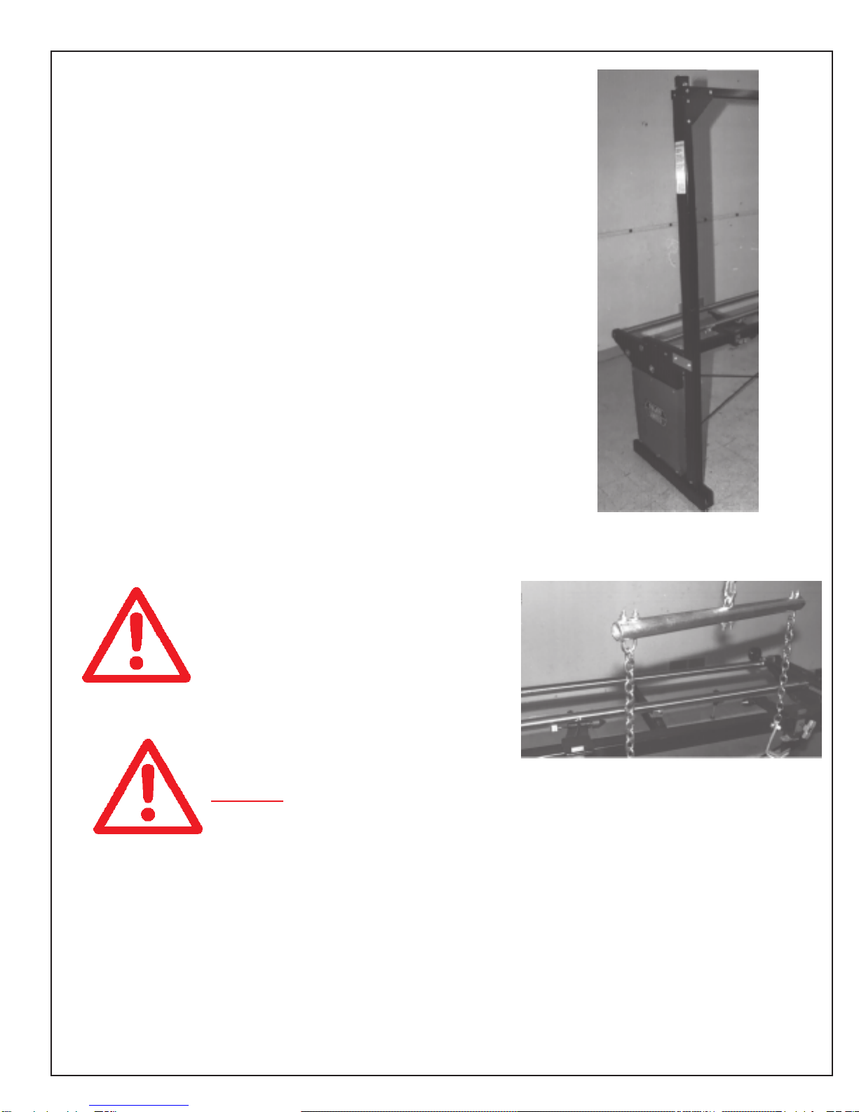
Remove Main Base Assembly from wood pallet.
The Main Base Assembly weighs
215 lbs (100 kg). To lift, use power
equipment or get adequate help.
To remove the Main Base Assembly from the wood pallet:
1. Unbolt the four lag bolts that hold each end of the
Main Base Assembly to the pallet.
NOTE: A number symbol and number in parenthesis (#__)
refers to the item number in the parts list section of this
manual.
UNCRATING AND ASSEMBLY INSTRUCTIONS

4
ASSEMBLE LEG LEVELERS TO
BASE ASSEMBLY
Place leg leveler foot (#43) and 1/2" nut (#60) into tapped
holes in cast leg base (#5), see FIG. 1, and adjust to a uni-
form 1" [25 mm] leaving the nut loose.
LOCATE AND LEVEL THE GRINDER
Set the Grinder on a level concrete floor, on a single
uncracked slab of concrete.
Placing the grinder on a floor that is
badly out of level or broken will
affect grinding quality.
If the unit must be located near a wall, allow adequate space
for operating and servicing. The clearance required around
the grinder is a 36" [90 cm] minimum on the two sides and the
frontand 48" [120 cm]minimum to the rear as shown in FIG. 2.
Place a level on the front carriage rail near the center of the
machine and check the level from left to right. See FIG. 3.
Adjust the leveling feet until the machine is level.
Place the level across the front and rear carriage rails
near the left end of the machine. See FIG. 4. Adjust the
two leveling feet on the left end until the rails are level.
Place the level across the front and rear carriage rails
near the right end of the machine. Level the right end in
the same way as the left end. See FIG. 5. For grinding
accuracy, the two ends must be level within +/- .015 in.
(.4 mm) so the frame is not twisted.
Recheckthelevelinboth directions. Whensatisfactory,tighten
the hex jam nuts (#60) on the leveling feet securely against
the bottom of the base. See FIG. 1. Do not turn the leveling
feet when tightening.
Again recheck the level after the nuts are firmly tightened.
For grinding accuracy, the machine
does not have to be perfectly level.
However, IT IS CRITICAL that
front-to-back leveling be the same at
both ends of the machine.
INSTALLATION
FIG. 5
FIG. 1
FIG. 2
FIG. 3
FIG. 4
55
INSTALL REEL ELEVATOR
Bolt the left and right end frames to the top and bottom mounting
brackets already attached to the end panels using four 3/8-16 x
3/4" hex head cap screws (#14), two flatwashers over the top
bracket slots (#19), four lock washers (#21) and four nuts (#16).
The mounting bracket might have to be loosened and adjusted to
line up with the end frames. Bolt the end frame with the decal on
the winch end (right end of unit as viewed from the operator’s
position) See FIG. 6. Bolt gussets loosely to the overhead channel,
which is installed with the pulleys on top, using eight 3/8-16 x 3/4"
long hex head screws (#14), eight lock washers (#21) and eight
nuts (#16). Lift overhead channel into position (Note the position
of the bracket in FIG. 6) and bolt to end frames using eight 3/8-16
x 3/4" long hex head screws (#14), lock washers (#21) and nuts
(#16). Align and securely tighten all nuts.
Attach the winch to the right side of unit as viewed from the
operator’s position with the crank handle facing to the rear. In-
stall two 3/8-16 x 3/4" long hex head cap screws (#14) and one
flatwasher(#19), two lock washers (#21) and two nuts (#16). The
flatwashergoesover the winch housing slot. Assemble the winch
according to the instructions provided in the manual packet.
Thread the cable through the top middle hole in the channel
and over both pulleys. Attach the cable to the winch following
the procedure described in the winch instructions.
The cable is reeled up by rotating handle in a clockwise direction,
as it is reeled up it makes a clicking sound. The spring loaded
handle actuates a brake when handle is released.
Read separate directions on winch
operation and maintenance that is
included in the manual packet.
Placespreaderbarwith chains and hooks onto cable hook (which
has safety latch feature built in). See FIG. 7.
Do not overload the winch capacity.
Winch capacity is a maximum of
400 lbs. (180 kg)
INSTALLATION (Continued)
FIG. 6
FIG. 7
6
INSTALLATION (Continued)
ASSEMBLE OVERHEAD SUPPORT ARM & BAR
Assemble overhead support arm (#25) and (#26) using four
3/8 x 2-1/4" cap screws (#51), four 3/8" nuts (#59), and four
lock washers (#13). Sandwich the warning panel assembly
(#70) between left hand end frame (#2) and the left side
support arm (#25).
Warning panel assembly must be
installed to protect the operator
and visitors.
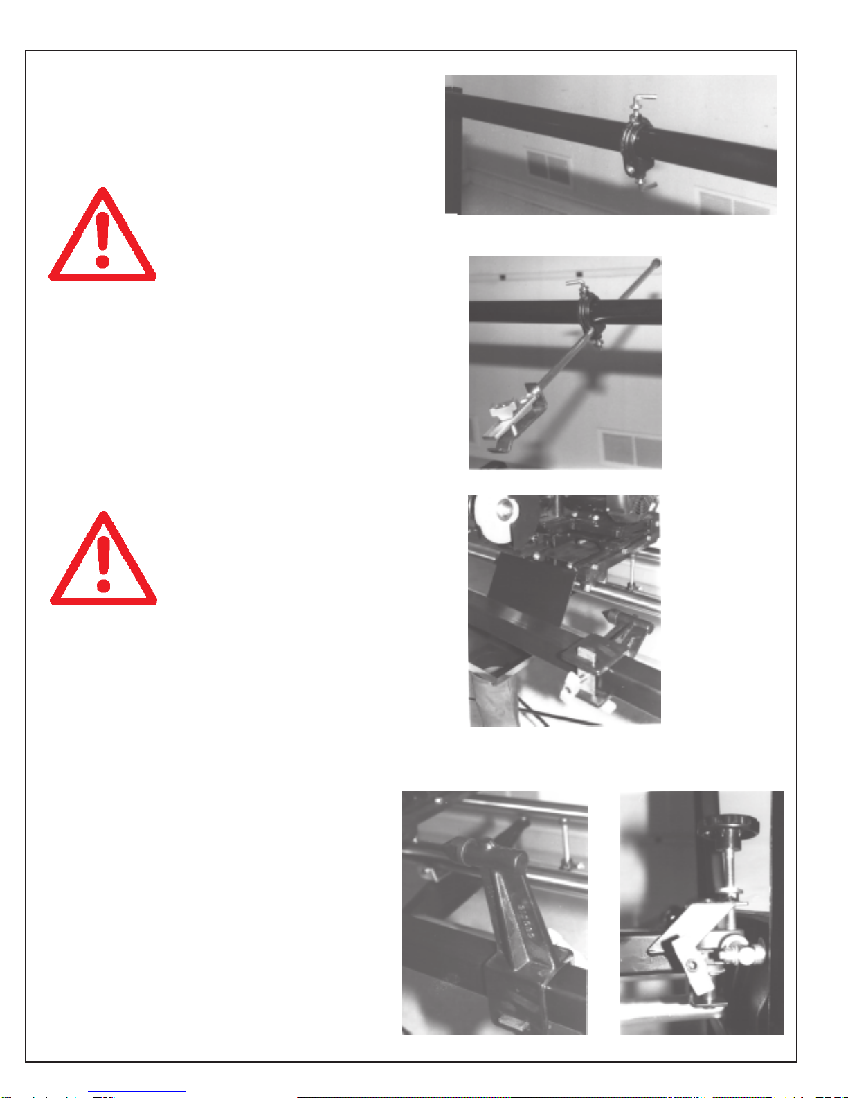
Install two overhead clamp castings (#8) onto the overhead
bar (#37) as shown in FIG. 8. Assemble overhead bar
(#37) with two 3/8" x 3/4" cap screws (#48) & two lock
washers (#13) being sure to place overhead clamp castings (#8)
onto overhead bar as shown before assembling. See FIG. 8.
Assemble the overhead clamp assemblies. (#45,46,47,62)
onto the overhead clamp castings (#8). Assemble bumper (# 65)
onto mower clamp weldment (#46). See FIG. 9.
MOUNT GRINDING HEAD ASSEMBLY
The Grinding Head Assembly weighs
approximately 85 lbs (40 kg). To lift,
use power equipment or get adequate
help.
Place grinding head assembly onto machine rails. Position
the carriage travel stops (#35) and clamp into place.
Remove grinding wheel guard (#5), install the 6" diameter x 3/8"
wide grinding wheel (#30) and snugly hand tighten. Adjust
the guide finger (#13) and tighten. Then reinstall the grinding
wheel guard (#5).
INSTALL DUST DEFLECTOR SHIELD
Attach the dust deflector shield with two 3/8-16 x 3/4"
cap screws (#40) and two lock washers (#42). Install
Dust Bag (#35) and Hose Clamp (#57). See FIG. 10.
TOOLING BAR COMPONENTS
The reel support centers are mounted horizontally on
the tooling bar. Reposition them vertically on the
tooling bar at this time. See FIGS. 10 and 12.
Assemble the vertical adjusting screw (#33) and lock
(#15). Center the horizontal adjusting screw (#34).
See FIG. 13.
FIG. 13
FIG. 12
FIG. 8
FIG. 9
FIG. 10
77
INSTALLATION (Continued)
FIG. 14
FIG. 15
FIG. 16
Wiring,
as built.
To convert to wiring.
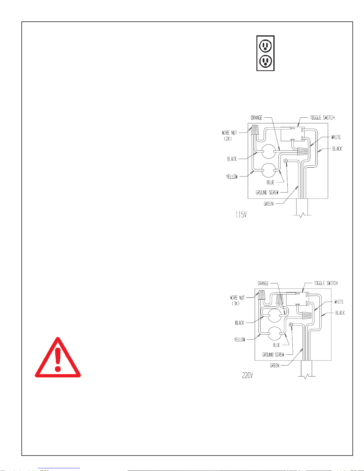
MOTOR WIRING &
GROUNDING INSTRUCTIONS
Your Model 388 Grinder has been completely prewired at
thefactory, andnoadditionalwiring is necessary. TheModel
388 is set up for a 115 VAC, 50/60 HZ 1 Phase - current.
The grinder operates on a 15 AMP circuit. The wall outlet
should be grounded and look like the outlet shown in
FIG. 14. See FIG. 15 for 115 volt motor wiring, as built.
Toconvertthis grinder tooperateon220 V 50/60HZ1phase
current, cut the plug off from the cord and replace it with the
appropriateplug for yourlocality. For plugandcircuit breaker
sizing, see motor nameplate ratings. Use only a qualified
electrician.
To convert the grinder from 115 Volt to 220 Volt, disconnect
the four wires coming from the motor internally and
reconnect them as shown in FIG. 16. One additional wire
nut will be required to complete. NOTE: This motor will
operate correctly on 60 HZ or 50 HZ power.
GROUNDING INSTRUCTIONS
In the event of a malfunction or breakdown, grounding
provides a path of least resistance for electrical current to
reduce the risk of electrical shock. This tool is equipped
with an electrical cord having an equipment grounding
conductor and a grounding plug. The plug must be plugged
into the matching outlet that is properly installed and
groundedinaccordance with all local codesandordinances.
Before plugging in your machine, make sure it will be
connected to a supply circuit protected by a properly
sized circuit breaker or fuse.
Do not modify the plug provided if it will not fit the outlet,
have the proper outlet and circuit installed by a qualified
electrician.
Always properly electrical ground
your machine. An improper
connection can cause an electrical
shock. If unsure of the proper
electrical grounding procedure,
contact a qualified electrician.

8
MAINTENANCE
PERIODIC MAINTENANCE
1. Wipe and re-oil with a spray lubricant (do not use a teflon
based lubricant) lead screws once a month or every 40
hours of operation.
2. Wipe and re-oil with never-seez horizontal and vertical
cross slide shafts on mower support bar once a month or
every 40 hours of operation.
3. Lubricate the traverse rails with a spray lubricant (do not
use a teflon based lubricant) and wipe off the excess once
a month or every 40 hours.
4. Check Gib plate adjustment in the grinder carriage base
monthly or every 40 hours. See Page 9.
5. Check ALL Fasteners once every 3 months or 100 hours..
6. Clean dust bag when 1/2 full - approximately every 3
months or 100 hours.
7. Check the belt every 3 months or 100 hours. Check the
tension and look for cracks. See Page 9.
8. Wipe and grease carriage dovetail with lithium grease
every six months or every 200 hours of operation.
9. Rail Alignment - Check every 6 months or every 200
hours. See Page 9.
10. Rotate traverse shafts once a year or every 300 hours of
operation. See Page 9.

99
MAINTENANCE ADJUSTMENTS
GIB ADJUSTMENT
The four gib set screws should be adjusted by loosening the
four lock nuts and then turning in the set screws while turning
the horizontal infeed handwheel. Adjust the gib for a snug
movement of the slide and gib. To adjust all four set screws, it
will be necessary to move the slide from front to back. NOTE:
The slide must be fully in front of the gib screw when making
adjustments. DO NOT adjust the gib screw without the slide
positioned adjacent.
BELT TENSIONING AND REPLACEMENT
To adjust belt tension loosen the two set screws on the Head
Support and push the grinding head forward to tension the belt,
making sure to hold the head square and retighten the set
screws. Headsquarenessis shown on page 7 of the Operator's
Manual. After correctly tensioning the belt, check your tension
with a
5 lbs [2 kg] load applied approximately in the center of the belt,
you should observe 1/8" [3 mm] of deflection. See FIG. 17. To
change the belt, remove the two belt guards, and loosen the set
screwsontheHeadSupport. Push the grinding head in against
the internal spring and remove the belt. Install the new belt
andreversethesequencemaking certain to reinstall the guards.
DO NOT OVERTIGHTEN OR PRY ON THE
GRINDING HEAD TO TIGHTEN. DAMAGE
COULD OCCUR TO THE MOTOR OR GRINDING
HEAD BEARING.
RAIL ALIGNMENT AND ROTATION
The front (away from the operator) carriage rail is adjustable
in horizontal and vertical planes. The rear rail (nearest the
operator) is adjustable only in the vertical plane. Using a
PRECISION straight edge adjust the rails using the set screws
(#54) and locknuts (#57) as shown on pages 16 and 17.
Afterextendeduse, the carriage bearingswillstartto wear tracks
into the carriage rails. To minimize this, it is recommended that
once a year or every 300 hours of operation the carriage rails
should be turned. Loosen the set screws holding the carriage
rails and turn the rails so the bearings run on a new track.
Retighten the set screws. After rail turning, recheck rail
straightness.
FIG. 17

10
TROUBLESHOOTING
PROBLEM
PROBLEM
No electrical power to
grinding motor.
Reel ground in a
concave, convex, or
irregular shape.
This is determined by
irregularitiesin therelief
grind, i.e.: larger on
ends than center, vice
versa, irregular relief,
not uniform
POSSIBLE CAUSE
Main power source
is off.
Nottraversed manually
with uniform travel
speed.
Not a uniform travel
speed coming off the
end of reel blade.
Overhead clamps and
fixture clamps not
holding mower unit
tight.
Squaretube toolingbar
for fixture holding is not
rigid.
REMEDY
Turn on main circuit
breaker. Plugpower in.
Verify motor switch is
on.
Travel at a very steady
speed on the reel
blade.
Travel at a very steady
speed across the full
blade. Do not slow
down near the end of
the blade.
Tighten down all locking
hand knobs. Four hand
knobs for the square
tube side and bottom
clamps; two knobs for
the mower holding
clamps; and two knobs
for the mower clamp
swivel. Checkalignment
of overhead clamp so
thereisnobindingbefore
locking down of hand
knobs. Useallenwrench
for increased tightness
of appropriate knobs.
The pivot end is bolted
on rubber mounts. On
adjustable end, tighten
slide end locking
handles one for vertical
and one for horizontal
locking.
REASON
Irregular speed on the
blade will cause
irregular grind pattern.
To eliminate reel
movement during
grinding.
To eliminate reel
movement during
grinding.

1111
TROUBLESHOOTING CONT.
PROBLEM
Reel ground in a
concave, convex, or
irregular shape, cont.
POSSIBLE CAUSE
Grinding wheel head
moving.
Gibs loose on carriage.
Carriage ball bearings
worn outside diameter
or internal wear.
Grinding Head Bearing
has develped free play.
REMEDY
Tighten up two set
screws that hold the
Grinding Head into the
Head Support.
There is a lock handle
to tighten. It is the lock
handlewithanylon plug
atthetiptosetthetension
against the threads for
thegrindingwheelvertical
height adjustment
screw.
The two adjustable
cone point set screws
on the pivot of the mo-
tor plate need adjust-
mentso the motor plate
has no side movement.
Tighten gib screws to
prevent movement.
Adjust the motor slide
baseforwardandadjust
the gib screws. Then
adjust the motor slide
base all the way back
and adjust the final gib
screws.
Replace bearings.
Try to move the grinding
wheel from side to side
with the power
disconnected. If there
is more than .005" [.13
mm] side movement,
replace the grinding
head assembly.
REASON
To prevent grinding
head from moving
during grinding.
To prevent grinding
head from moving.
To prevent grinding
head from moving
during grinding.
To prevent the grinding
wheelfrommovingduring
grinding.

12
TROUBLESHOOTING CONT.
PROBLEM
Reel ground in a
concave, convex, or
irregular shape, cont.
POSSIBLE CAUSE
Tooling bar support
brackets are loose.
REMEDY
All reels are mounted
with two V-support
brackets or two center
support brackets. Be
suretheyare tighttothe
square tooling support
tube in horizontal and
vertical plane. Tighten
the horizontal locking
screws. First, firmly
pulling the center
bracket over to the side
of the tooling support
tube. Then tighten the
vertical locking handle
to pull down the
supports to the tooling
supporttube. Whenus-
ing center supports,
check to see if the fixed
center is screwed in
tight to its casting using
a wrench. The
adjustable center is to
be locked tight with the
locking hand knob.
REASON
When the supports are
not held tight to the
square tube, the reel
can move during
grinding.
Loose centers effect
grinding accuracy.

1313
TROUBLESHOOTING CONT.
PROBLEM
Reel ground in a
concave, convex, or
irregular shape, cont.
POSSIBLE CAUSE
Rails not straight.
Check rail towards the
reel side for
straightness in the
horizontal plane.
Rails not straight.
Checkvertical planefor
straightness of rails.
Carriage has varying
load in either direction
from grinding grit
buildup inside the
carriagebearingsorun-
even wear on the bear-
ing outside
diameter.
Rails have grinding grit
buildup and carriage
bearings do not track
straight.
REMEDY
Using a three foot long
PRECISION straight
edge, and feeler gage,
checkforamaximum of
.002 inch [.05 mm]
straightnessat thefront
edge of the front rail.
Front rail has three ad-
justing screws. Rear
rail has one adjusting
screw.
Using a three foot long
PRECISION straight
edge, and using a
feelergage, checkfor a
maximum of .003 inch
[.08 mm] straightness
at the top edge of the
front rail and rear rail.
Replace Bearings
Clean rails of grinding
grit.
REASON
Rail straightness
directly affects grind
straightness of the
outside diameter of
the reel in the
horizontal plane.
This plane is not as
criticalforreel grinding
accuracy,butstillmust
be held to tolerance
listed to hold grind
straightness of
outside diameter of
the reel.
Bearings will fail after
many hours of use.
Rails buildup with grit
during operation and
must be cleaned
often.

14
TROUBLESHOOTING CONT.
PROBLEM
Cone shape of reel.
Relief grind on the reel
blades does not go full
length.
Blades are turning blue
during grinding.
POSSIBLE CAUSE
Reel position not
parallel to
carriage travel.
Grinding wheel is not
correctly dressed.
Removing too much
material in one pass.
REMEDY
Use reel alignment
gage procedure
touchingoff onreel hub
to zero out the reel
positionfrom eachend.
(For more information,
see reel setup gage
procedure in manual.)
See the correct
grindingwheeldressing
procedure on page 15
of the Operator's
Manual.
Adjust the horizontal
infeed to remove less
material per pass.
REASON
Reel hub has to be
parallel to carriage
traverse rails so reel is
not cone shaped.
If grinding wheel is
improperly dressed
it will not grind
approximately the
last 3/8" of the blade.
Heavy material
removal builds up
heat and turn the
blade blue.

1515
--This page left blank intentionally, for note taking purposes--
16
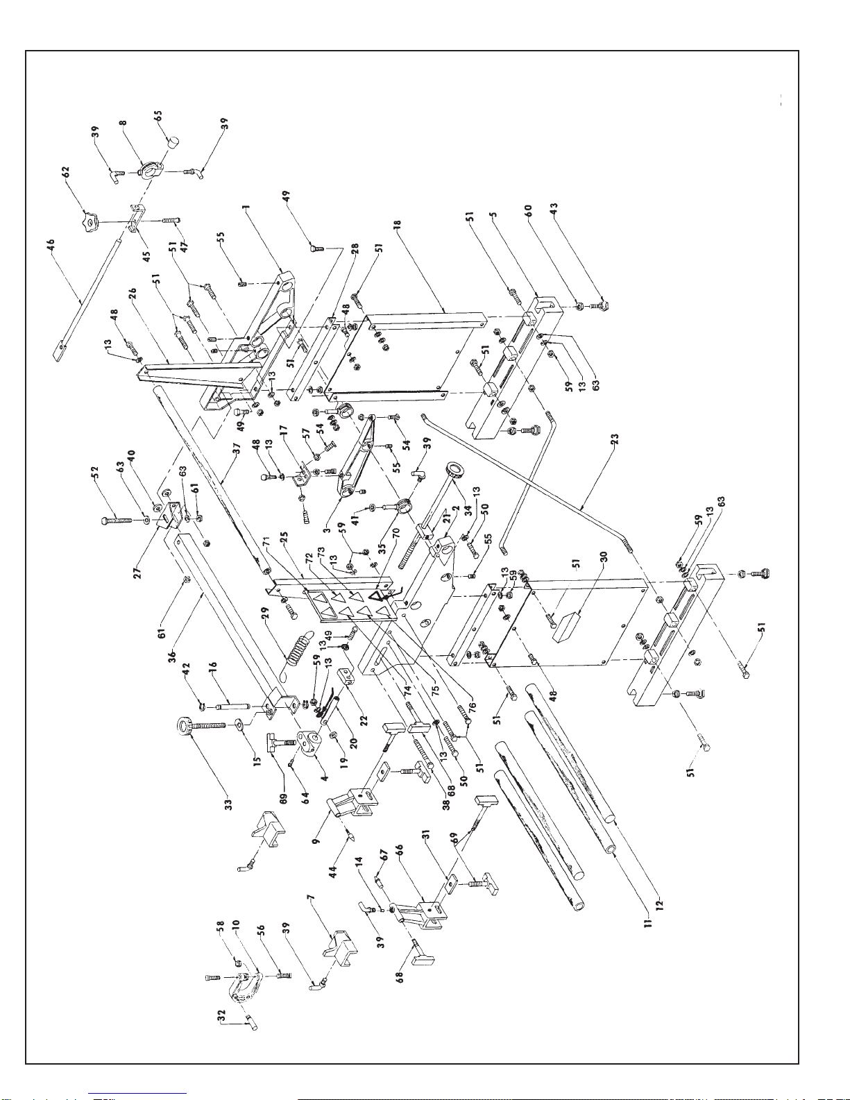
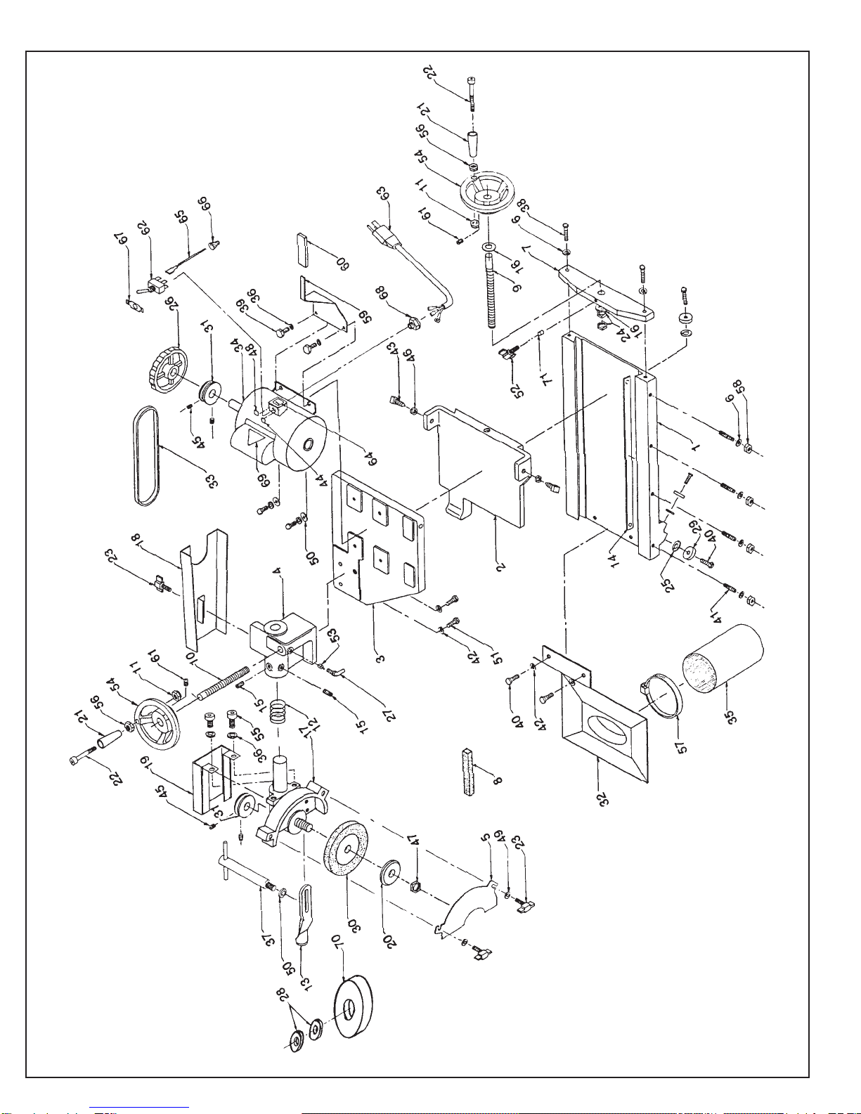
EXPLODED VIEW: 388 MAIN BASE ASSEMBLY
77
78

1717
PART NO.
3889001
3889002
3889003
3969012
3889009
3889014
3889015
3889016
3889017
3889031
3889032
K371501
3579109
3889035
3889039
3889041
3889043
3889045
3889046
3889047
3889048
3889049
3889051
3889052
3889053
3889054
3889055
3709990
3889066
3889067
3889510
3889511
3889514
3889521
3889522
B375601
3709253
3709254
3709255
3709331
PART NO.
3709563
6009517
3649078
3969547
A313202
B371201
B371601
B373201
B373601
B374801
C251602
C370820
C374000
J251000
J372000
J371000
J501000
J377100
3708262
K370001
R601018
3709258
3889022
6009020
6009577
6009555
3889112
3708524
3708461
3708526
3707458
3708525
3708527
3708528
K310101
DIAGRAM NO.
1
2
3
4
5
7
8
9
10
11
12
13
14
15
16
17
18
19
20
21
22
23
25
26
27
28
29
30
31
32
33
34
35
36
37
38
39
40
41
42
PART NAME
Right-Hand End Frame
Left-Hand End Frame
Strut
Cross Slide
Base
Roller Bracket
Overhead Clamp
Center Stand - Fixed
"C" Clamp
Frame Tie Bar
Carriage Rail
Lockwasher 3/8
Nylon Plug
Lock
Clevis Pivot Pin
Adjusting Bracket
End Frame Panel
Spacer
Cross Slide Shaft
Guide Block
Support Block
Tie Rod
Left-Hand Overhead Support Arm
Right-Hand Overhead Support Arm
"L" Bracket
End Cap
Spring - Support Bar
Decal
Center Stand Lock
Shoulder Pin
Vertical Adjust. Screw Assembly
Horizontal Adjust. Screw Assembly
Carriage Stop Assembly
Tube Weldment
Overhead Bar
Hex Cap Screw 3/8-16 x 3-1/2 Long
Lock Handle
Rubber Washer
Rubber Washer
Retaining Ring
DIAGRAM NO.
43
44
45
46
47
48
49
50
51
52
54
55
56
57
58
59
60
61
62
63
64
65
66
67
68
69
70
71
72
73
74
75
76
77
78
. . . . . . . . . .
. . . . . . . . . .
. . . . . . . . . .
. . . . . . . . . .
. . . . . . . . . .
. . . . . . . . . .
. . . . . . . . . .
. . . . . . . . . .
. . . . . . . . . .
. . . . . . . . . .
. . . . . . . . . .
. . . . . . . . . .
. . . . . . . . . .
. . . . . . . . . .
. . . . . . . . . .
. . . . . . . . . .
. . . . . . . . . .
. . . . . . . . . .
. . . . . . . . . .
. . . . . . . . . .
. . . . . . . . . .
. . . . . . . . . .
. . . . . . . . . .
. . . . . . . . . .
. . . . . . . . . .
. . . . . . . . . .
. . . . . . . . . .
. . . . . . . . . .
. . . . . . . . . .
. . . . . . . . . .
. . . . . . . . . .
. . . . . . . . . .
. . . . . . . . . .
. . . . . . . . . .
. . . . . . . . . .
. . . . . . . . . .
. . . . . . . . . .
. . . . . . . . . .
. . . . . . . . . .
. . . . . . . . . .
. . . . . . . . . .
. . . . . . . . . .
. . . . . . . . . .
. . . . . . . . . .
. . . . . . . . . .
. . . . . . . . . .
. . . . . . . . . .
. . . . . . . . . .
. . . . . . . . . .
. . . . . . . . . .
. . . . . . . . . .
. . . . . . . . . .
. . . . . . . . . .
. . . . . . . . . .
. . . . . . . . . .
. . . . . . . . . .
. . . . . . . . . .. . . . .
. . . . .
. . . . .
. . . . .
. . . . .
. . . . .
. . . . .
. . . . .
. . . . .
. . . . .
. . . . . . . . . . . . . . .
. . . . . . . . . .
. . . . .
. . . . . . . . . .
. . . . . . . . . .
. . . . . . . . . .
. . . . . . . . . .
. . . . . . . . . .
. . . . . . . . . .
. . . . . . . . . .
. . . . . . . . . .
. . . . . . . . . .
. . . . . . . . . .
. . . . . . . . . .
. . . . . . . . . .
. . . . . . . . . .
. . . . . . . . . .
. . . . .
. . . . .
. . . . .
. . . . .
. . . . .
. . . . .
. . . . .
. . . . .
. . . . .
. . . . .
. . . . .
. . . . .
. . . . .
. . . . .
. . . . .
. . . . .
. . . . .
. . . . .
. . . . .
. . . . .
. . . . .
. . . . .
. . . . .
. . . . .
. . . . .
. . . . .
. . . . .
. . . . .
. . . . .
. . . . .
. . . . .
. . . . .
. . . . .
PART NAME
Adjust Leveling Bolt
Center - Fixed
Clamp Lip
Mower Clamp Weldment
Round Head Machine Screw 5/16-18 x 2" Long
Hex Cap Screw 3/8-16 x 3/4" Long
Hex Cap Screw 3/8-16 x 1" Long
Hex Cap Screw 3/8-16 x 2" Long
Hex Cap Screw 3/8-16 x 2-1/4 " Long
Hex Cap Screw 3/8-16 x 3" Long
Square Hd Set Screw Oval Point 1/4-20 x 1" Long
Sock Set Screw 3/8-16 x 2-1/2" Long
Square Hd Set Screw 3/8-16 x 2-1/2" Long
Hex Nut 1/4-20
Hex Jam Nut 3/8-16
Hex Nut 3/8-16
Hex Nut 1/2-13
Hex Nut Nylok 3/8-16
Knob 5/16-18 x 1.50 Wide
Plain Washer 3/8
Drive Screws No. 2 Round Head
Bumper
Center Stand - Adjustable
Center - Adjustable
Knob Assy
Knob Assy
Warning Panel
Warning Decal - Glasses
Warning Decal - 3600 RPM
Warning Decal - No Fuel
Warning Decal - Sharp
Warning Decal - Stay Clear
Warning Decal - Respirator
Warning Decal - Hearing Protection
Flat Washer - Heavy
. . . . .
. . . . .
. . . . .
. . . . .
. . . . .
. . . . .
. . . . .
. . . . .
. . . . .
. . . . .
. . . . .
. . . . .
. . . . .
. . . . .
. . . . .
. . . . .
. . . . .
. . . . .
. . . . .
. . . . .
. . . . .
. . . . .
. . . . .
. . . . .
. . . . .
. . . . .
. . . . .
. . . . .
PARTS LIST: 388 MAIN BASE ASSEMBLY
. . . . . . . . . .
. . . . . . . . . . . . . . .
. . . . .
18
EXPLODED VIEW: 388 GRINDING HEAD ASSEMBLY

1919
DIAGRAM NO. PART NO. PART NAME
41 . . . . .C252420 . . . . . . Socket Setscrew 1/4-20x1-1/2" Long
42 . . . . .K371501 . . . . . . 3/8" Lockwasher
43 . . . . .C372000 . . . . . . Square Head Setscrew 3/8-16x1-1/4" Long
44 . . . . .3708460 . . . . . . Start Decal
45 . . . . .C250620 . . . . . . Socket Setscrew 1/4-20x3/8" Long
46 . . . . .J372000 . . . . . . 3/8-16 Hex Jam Nut
47 . . . . .J502100 . . . . . . 1/2-20 Hex Jam Nut
48 . . . . .3708459 . . . . . . Emergency Stop Decal
49 . . . . .K250001 . . . . . . 1/4" Flat Washer
50 . . . . .K310001. . . . . . .5/16" Flat Washer
51 . . . . .B371601 . . . . . . Hex Head Cap Screw 3/8-16x1" Long
52 . . . . .6109597 . . . . . . Tee Knob Assembly
53 . . . . .3579109 . . . . . . Nylon Plug 3/16"
54 . . . . .3708155 . . . . . . Hand Wheel
55 . . . . .B310811. . . . . . Socket Head Cap Screw 5/16-18x1/2" Long
56 . . . . .J252000 . . . . . . 1/4-20 Hex Jam Nut
57 . . . . .3709804 . . . . . . Hose Clamp
58 . . . . .J251000 . . . . . . 1/4-20 Hex Nut
59 . . . . .3889110 . . . . . . Carriage Handle Bracket
60 . . . . .3709624 . . . . . . Plastic Handle
61 . . . . .C310420. . . . . . Socket Setscrew 5/16-18x1/4" Long
62 . . . . .3707070 . . . . . . Toggle Switch
63 . . . . .3707034 . . . . . . Cord Set
64 . . . . .3707130 . . . . . . Warning Decal
65 . . . . .3707188 . . . . . . Wire Assembly
66 . . . . .3707264 . . . . . . Wire Nut
67 . . . . .3707316 . . . . . . On-Off Switch Plate
68 . . . . .3707976 . . . . . . Conduit Connector
69 . . . . .3708448 . . . . . . Warning Decal - Electrical
70 . . . . .3700265 . . . . . . Grinding Wheel 6x1x1.25 Bore 60 Grit
Straight Cupped Vitrified Ruby
71 . . . . .3579284 . . . . . . Nylon Plug 1/8"
** . . . . . 3700067 . . . . . . Grinding Wheel 6-4x1x1.25 Bore 60 Grit
Flared Cupped Vitrified Ruby
** . . . . . 3700266 . . . . . . Grinding Wheel 6x1x1.25 Bore 46 Grit
Straight Cupped Vitrified Grey
** OPTIONAL
DIAGRAM NO. PART NO. PART NAME
1 . . . . . .3889005 . . . . . . Carriage Base
2 . . . . . .3889006 . . . . . . Slide
3 . . . . . .3889007 . . . . . . Motor Plate
4 . . . . . .3889008 . . . . . . Head Support
5 . . . . . .6009037 . . . . . . Grinding Wheel Guard
6 . . . . . .K251501 . . . . . . 1/4" Lockwasher
7 . . . . . .3889136 . . . . . . Feed Screw Guide
8 . . . . . .3702508 . . . . . . Dressing Stick .75x.75x3"
9 . . . . . .3889056 . . . . . . Feed Screw
10 . . . . .3889057 . . . . . . Elevating Screw
11 . . . . .J257000 . . . . . . 1/4-20 Locknut - Thin
12 . . . . .3889059 . . . . . . Compression Spring
13 . . . . .6009133 . . . . . . Reel Guide Finger
14 . . . . .6009025 . . . . . . Gib Plate
15 . . . . .C310826 . . . . . . 5/16-18x1/2 Long Dog Point Setscrew
16 . . . . .3709027 . . . . . . Thrust Washer
17 . . . . .3889502 . . . . . . Grinding Head Assembly
18 . . . . .3889523 . . . . . . Motor Belt Guard
19 . . . . .3889509 . . . . . . Grinding Head Belt Guard
20 . . . . .3649018 . . . . . . Outer Flange
21 . . . . .3709370 . . . . . . Spinning Handle
22 . . . . .B255011 . . . . . . 1/4-20x3-1/8 Long Socket Head Cap Screw
23 . . . . .6009598 . . . . . . Tee Knob Assembly
24 . . . . .3709214 . . . . . . Hex Jam Nut 1/2-13 LH
25 . . . . .3709216 . . . . . . Retaining Washer
26 . . . . .3889098 . . . . . . Handwheel
27 . . . . .3709253 . . . . . . Lock Handle
28 . . . . .3700408 . . . . . . Reducer Bushing
29 . . . . .3709257 . . . . . . Ball Bearing
30 . . . . .3700363 . . . . . . Grinding Wheel 6x3/8x1/2 Bore 46 Grit Vitrified Ruby
31 . . . . .3889088 . . . . . . Pulley
32 . . . . .3889501 . . . . . . Dust Collector
33 . . . . .3709764 . . . . . . V - Belt
34 . . . . .3707991 . . . . . . Motor 115/220V 60/50HZ 1 Phase
35 . . . . .3708146 . . . . . . Dust Bag
36 . . . . .K311501 . . . . . . 5/16 Lockwasher
37 . . . . .6009535 . . . . . . Tee Handle Assembly
38 . . . . .B251601 . . . . . . Hex Head Cap Screw 1/4-20x1" Long
39 . . . . .B311401 . . . . . . Hex Head Cap Screw 5/16-18x7/8" Long
40 . . . . .B371201 . . . . . . Hex Head Cap Screw 3/8-16x3/4" Long
MODEL 388 GRINDING HEAD ASSEMBLY
20
DIAGRAM NUMBER
1
2
3
4
5
6
7
8
9
10
11
12
13
14
15
16
17
18
19
20
21
22
23
24
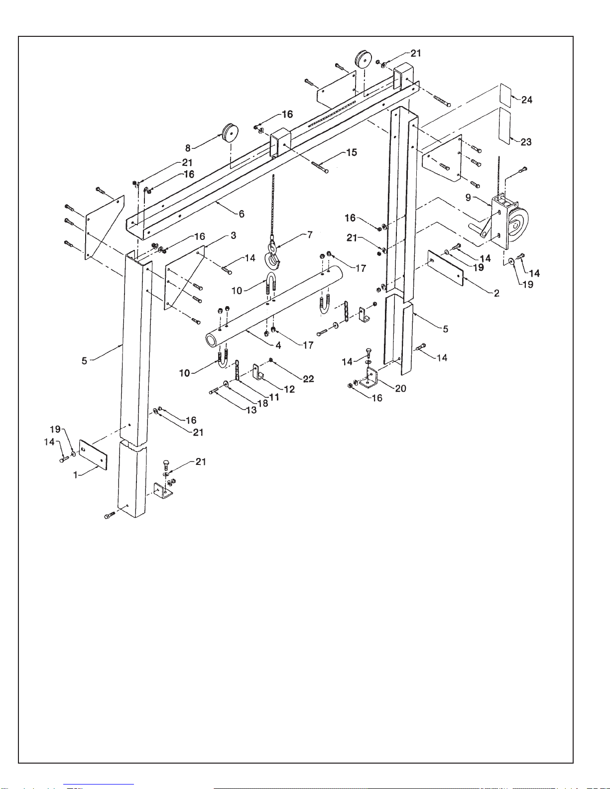
PARTS LIST: 388 ELEVATOR ASSEMBLY
PART NAME
Anchor Strap
Anchor Strap
Gusset
Spreader
End Frame
OverheadChannelWeldment
Hook and Cable Assembly
Pulley
Winch
"U" Bolt
Chain
Grab Hook
Hex Cap Screw 3/8-16 x 1.00 Long
Hex Cap Screw 3/8-16 x 3/4" Long
Hex Cap Screw 3/8-16 x 1-3/4" Long
Hex Nut 3/8-16
Hex Nut Nylok 5/16-18
Plain Washer
Plain Washer 3/8
AngleTab
Lock Washer 3/8
Hex Nut Nylok 3/8-16
Winch Warning Decal
Winch Warning Decal - Symbol
PART NUMBER
3889068
3889069
3889071
6009011
6009166
3889526
3709407
3709795
3709796
3709316
3649005
6009102
B371601
B371201
B372801
J371000
J317100
R000453
K370001
3889074
K371501
J377100
6009099
3708449
. . . . . . . . . . . . . . . . . . . . .
. . . . . . . . . . . . . . . . . . . . .
. . . . . . . . . . . . . . . . . . . . .
. . . . . . . . . . . . . . . . . . . . .
. . . . . . . . . . . . . . . . . . . . .
. . . . . . . . . . . . . . . . . . . . .
. . . . . . . . . . . . . . . . . . . . .
. . . . . . . . . . . . . . . . . . . . .
. . . . . . . . . . . . . . . . . . . . . . . . . . . . . . . . . . . . . . . . .
. . . . . . . . . . . . . . . . . . . .
. . . . . . . . . . . . . . . . . . . .
. . . . . . . . . . . . . . . . . . . .
. . . . . . . . . . . . . . . . . . . .
. . . . . . . . . . . . . . . . . . . .
. . . . . . . . . . . . . . . . . . . .
. . . . . . . . . . . . . . . . . . . .
. . . . . . . . . . . . . . . . . . . .
. . . . . . . . . . . . . . . . . . . . .
. . . . . . . . . . . . . . . . . . . . .
. . . . . . . . . . . . . . . . . . . . .
. . . . . . . . . . . . . . . . . . . . .
. . . . . . . . . . . . . . . . . . . . .
. . . . . . . . . . . . . . . . . . . . .
. . . . . . . . . . . . . . . . . . . . .
. . . . . . . . . . . . . . . . . . . . . . . . . . . . . . . . . . . . . . . . .
. . . . . . . . . . . . . . . . . . . .
. . . . . . . . . . . . . . . . . . . .
. . . . . . . . . . . . . . . . . . . .
. . . . . . . . . . . . . . . . . . . .
. . . . . . . . . . . . . . . . . . . .
. . . . . . . . . . . . . . . . . . . .
. . . . . . . . . . . . . . . . . . . .
. . . . . . . . . . . . . . . . . . . .
. . . . . . . . . . . . . . . . . . . . .
. . . . . . . . . . . . . . . . . . . . .
. . . . . . . . . . . . . . . . . . . . .
. . . . . . . . . . . . . . . . . . . . .
. . . . . . . . . . . . . . . . . . . . .
. . . . . . . . . . . . . . . . . . . . . . . . . . . . . . . . . . . . . . . . .
. . . . . . . . . . . . . . . . . . . .
. . . . . . . . . . . . . . . . . . . .
. . . . . . . . . . . . . . . . . . . .
. . . . . . . . . . . . . . . . . . . .
. . . . . . . . . . . . . . . . . . . .
. . . . . . . . . . . . . . . . . . . . .
Table of contents
Other Foley United Grinder manuals


Popular Grinder manuals by other brands

Napa/Evercraft
Napa/Evercraft 775-0232 Instruction manual & parts breakdown

Desoutter
Desoutter KA309-9 manual

Speedaire
Speedaire 10D235 Operating instructions & parts manual

Bosch
Bosch Professional GWS 12-125 CIP Original instructions

Bluerock Tools
Bluerock Tools 120D Operational manual

Bluebird
Bluebird SG1314A Operator's manual


