Foley United 633 User manual

ORIGINAL INSTRUCTIONS
THIS BOOK CONSISTS OF TWO MANUALS:
The OPERATOR'S MANUAL, which contains all the
informaon to install, operate, and perform daily
maintenance on this equipment.
The SERVICE MANUAL, which is used by the
maintenance department to do all maintenance,
except roune daily maintenance.
633
AUTO - INDEX
SPIN / RELIEF
REEL GRINDER

ORIGINAL INSTRUCTIONS
We are commied to:
Providing superior customer support, training, and service.
Manufacturing the highest quality products at an unequaled
value.
Seng the industry standard by invesng in technological
product innovaon.
Manufacturing products specically designed to maintain
original equipment manufacturers' specicaons.
Interacng with and supporng all original equipment
manufacturers.

ORIGINAL INSTRUCTIONS
633
AUTO - INDEX
SPIN / RELIEF
REEL MOWER GRINDER
Patent No. 5,321,912
6,010,394 & 6,290,581
6,685,544 & 6,699,103
OPERATOR'S
MANUAL
6337950 (12-16)
YOU MUST THOROUGHLY READ AND UNDERSTAND ALL MANUALS BEFORE
OPERATING THE EQUIPMENT, PAYING PARTICULAR ATTENTION TO THE WARNING &
SAFETY INSTRUCTIONS.
4
ORIGINAL INSTRUCTIONS
IMPORTANT SAFETY MESSAGE
and a
READ AND FULLY UNDERSTAND ALL THE SAFETY PRACTICES DISCUSSED IN THIS
MANUAL. ALL SAFETY RULES MUST BE UNDERSTOOD AND FOLLOWED BY ANYONE
WHO WORKS WITH REEL GRINDERS.
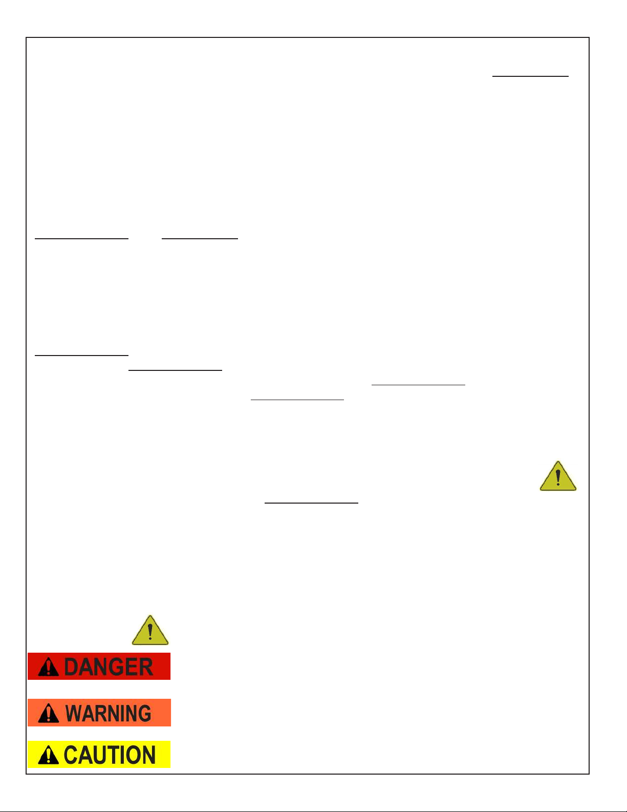
This symbol is used throughout this manual to call aenon to the safety
procedures.
The word DANGER indicates an immediate hazardous situaon, which if not
avoided, will result in death or serious injury.
The word WARNING indicates a potenal hazardous situaon, which if not
avoided, could result in death or serious injury.
The word CAUTION preceded with a safety alert symbol indicates a potenal
hazardous situaon which, if not avoided, may result in minor or moderate injury.
THROUGHOUT THIS MANUAL, THE FOLLOWING SAFETY SYMBOLS WILL BE USED TO INDICATE THE
DEGREE OF HAZARDS.

5
ORIGINAL INSTRUCTIONS
TABLE OF CONTENTS
THIS MACHINE IS DESIGNED FOR SHARPENING REEL TYPE MOWER BLADES ONLY. ANY USE OTHER
THAN THIS MAY CAUSE PERSONAL INJURY AND VOID THE WARRANTY.
TO ASSURE THE QUALITY AND SAFETY OF YOUR MACHINE AND TO MAINTAIN THE WARRANTY, YOU
MUST USE ORIGINAL EQUIPMENT MANUFACTURER'S REPLACEMENT PARTS AND HAVE ANY REPAIR
WORK DONE BY A QUALIFIED PROFESSIONAL.
ALL OPERATORS OF THIS EQUIPMENT MUST BE THOROUGHLY TRAINED BEFORE OPERATING
THE EQUIPMENT.
DO NOT USE COMPRESSED AIR TO CLEAN GRINDING DUST FROM THE MACHINE. THIS DUST CAN
CAUSE PERSONAL INJURY AS WELL AS DAMAGE TO THE GRINDER.
PREPARATION/INSTALLATION CHECK LIST
BEFORE USING THIS EQUIPMENT REFER TO THE LIST BELOW. VERIFY THAT ALL OF THE LISTED ITEMS
ARE COMPLETED BEFORE POWERING UP THE EQUIPMENT:

6
ORIGINAL INSTRUCTIONS
SPECIFICATIONS
OPERATING CONDITIONS: THIS MACHINE IS INTENDED FOR INDOOR USE ONLY.
AMBIENT TEMPERATURE: ................+5°C/ 40°F to +40°C/ 100°F
RELATIVE HUMIDITY: ......................
ALTITUDE: .......................................
TRANSPORTATION AND STORAGE:...-25°C/-15°F to +55°C / 130°F
SOUND LEVEL: ...............................
Means must be provided to prevent damage from humidity, vibraon and shock.
FIG. 1

7
ORIGINAL INSTRUCTIONS
DO NOT USE COMPRESSED AIR TO CLEAN GRINDING DUST FROM GRINDER.
LOW VOLTAGE RELAY
DAILY INSPECTION
INTERLOCK SYSTEM
THE DAILY INSPECTION SHOULD BE
PERFORMED ONLY WHEN THE MACHINE IS
OFF AND ALL MOTORS HAVE STOPPED.
NEVER OPERATE EQUIPMENT WITH THE INTERLOCK SYSTEM DISCONNECTED OR
MALFUNCTIONING. NEVER DISCONNECT OR BYPASS ANY SWITCH OR GUARDING.
1.
2.
3.
4.

8
ORIGINAL INSTRUCTIONS
SAFETY INSTRUCTIONS
TO AVOID INJURY, READ AND UNDERSTAND THE SAFETY ITEMS LISTED BELOW. IF YOU DO
NOT UNDERSTAND ANY PART OF THIS MANUAL AND NEED ASSISTANCE, CONTACT YOUR
LOCAL DEALER OR THE MANUFACTURER.
13. MAINTAIN GRINDER WITH CARE.
14. DISCONNECT POWER BEFORE SERVICING,
15. REDUCE THE RISK OF UNINTENTIONAL
STARTING.
16. USE RECOMMENDED ACCESSORIES.
17. CHECK FOR DAMAGED PARTS.
18. NEVER LEAVE THE GRINDER RUNNING
UNATTENDED. TURN THE POWER OFF.
19. KNOW YOUR EQUIPMENT.
20. KEEP ALL SAFETY DECALS CLEAN AND LEGIBLE.
21. DO NOT OPERATE GRINDER WHEN UNDER
THE INFLUENCE OF DRUGS, ALCOHOL, OR
MEDICATION.
1. KEEP GUARDS IN PLACE
2. REMOVE WRENCHES AND OTHER TOOLS.
3. KEEP WORK AREA CLEAN.
4. DON'T USE IN DANGEROUS ENVIRONMENT.
5. KEEP ALL VISITORS AWAY.
6. MAKE THE WORK AREA CHILD-PROOF
7. DON'T FORCE THE GRINDER.
8. USE THE RIGHT TOOL.
9. WEAR PROPER APPAREL.
10. ALWAYS USE SAFETY GLASSES.
11. SECURE YOUR WORK.
12. DON'T OVERREACH.

9
ORIGINAL INSTRUCTIONS
SAFETY INSTRUCTIONS
IMPROPER USE OF GRINDING WHEEL MAY CAUSE BREAKAGE AND SERIOUS INJURY.
DO
1. DOHANDLE AND STORE
CAREFUL
2. DO VISUALLY INSPECT
3. DO CHECK MACHINE SPEED
4. DO CHECK MOUNTING FLANGES
5. DO USE MOUNTING BLOTTERS
6. DOWORK REST
7. DOUSE A SAFETY GUARD
COVERING
8. DONEWLY MOUNTED WHEELS
9. DOWEAR SAFETY GLASSES
DON'T
1. DON'THAS
BEEN DROPPED
2. DON'T FORCEOR
ALTER
3. DON'TEXCEED THE MAXIMUM
OPERATING SPEED
4. DON'T
ARE NOT CLEAN, FLAT
AND FREE OF BURRS.
5. DON'T TIGHTEN
6. DON'TSIDE OF THE WHEEL
7. DON'TWHEEL
GUARD IS IN PLACE.
8. DON'T JAM
9. DON'T STAND DIRECTLY IN FRONT
10. DON'T FORCE THE GRINDING
AVOID INHALATION OF DUST
Grinding is a safe operaon if the few basic rules listed below are followed. These rules are based on
material contained in the ANSI B7.1 Safety Code for "Use, Care and Protecon of Abrasive Wheels". For
your safety, we suggest you benet from the experience of others and carefully follow these rules.
10
ORIGINAL INSTRUCTIONS
SAFETY INSTRUCTIONS
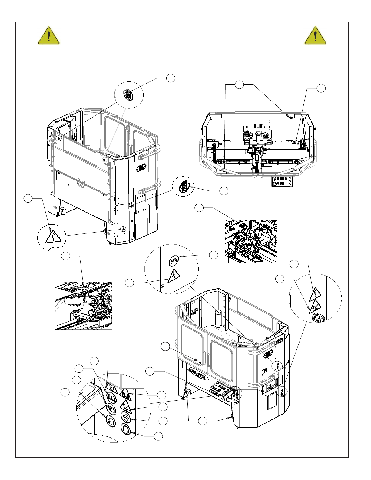
SAFETY DECALS - LOCATION.
IF ANY DECALS ARE DAMAGED, REPLACE THEM IMMEDIATELY!
See next page for explanaon of symbols and decals.
12
8
DETAIL A
SCALE 1 : 5
13
3
5
61
10
4
7
2
8
17
11
15 9
16
9
14
19
14
14
11
ORIGINAL INSTRUCTIONS
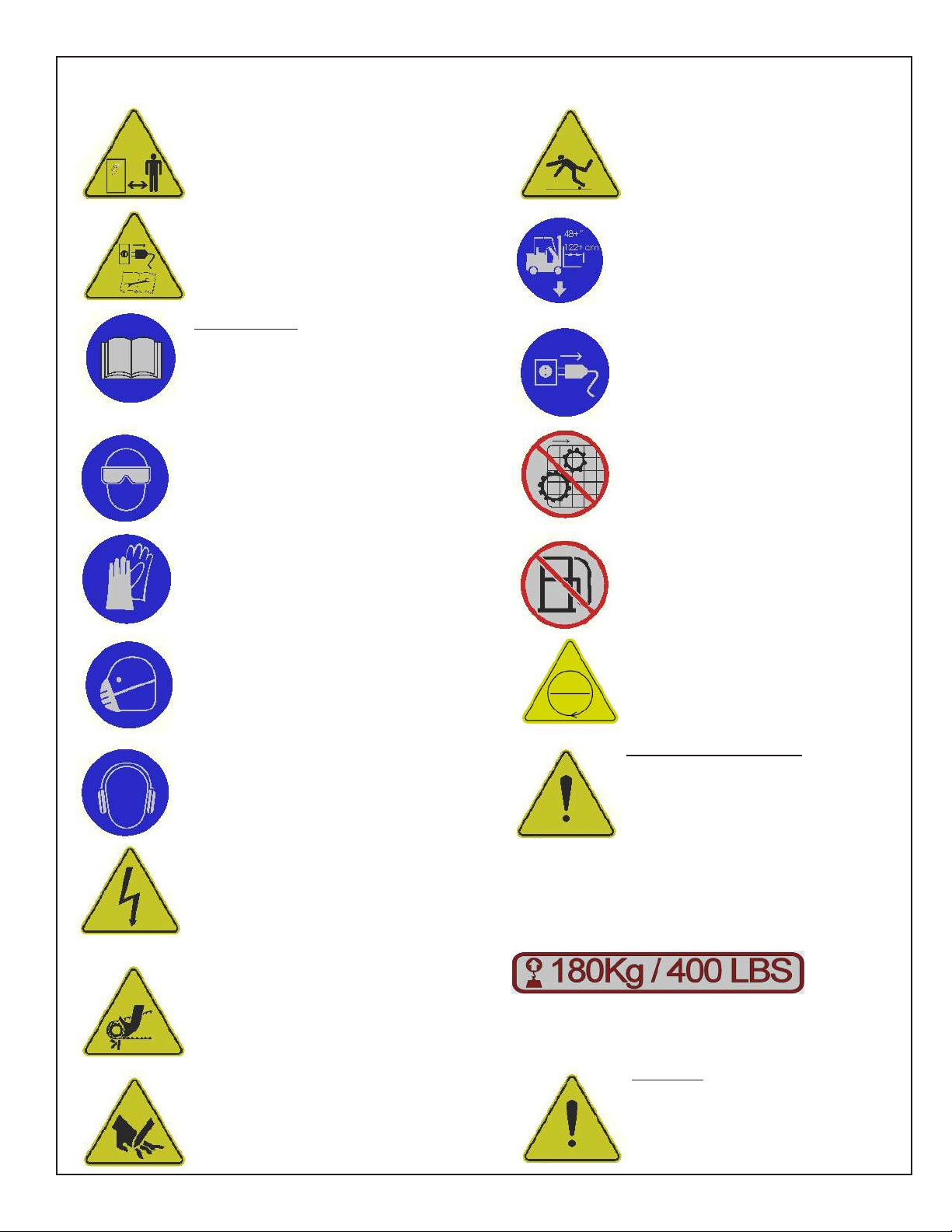
SAFETY INSTRUCTIONS
READ AND UNDERSTAND AND LOCATE ALL DECALS ON THIS MACHINE BEFORE OPERATING
THIS EQUIPMENT.
1
2
11
10
9
8
7
6
5
4
3
17
15
14
13
12
Keep hands clear of sharp
edges!
DANGEROUS
HIGH VOLTAGES PRESENT
REFER SERVICING TO
QUALIFIED SERVICE PERSONNEL ONLY.
must wear respirators or have
adequate venlaon systems.
WARNING! Hearing protecon required
Refer to manual
POWER CORD PROTECTION
hand
protecon is required
16
MIN
3600
18
19 VACUUM -
12
ORIGINAL INSTRUCTIONS
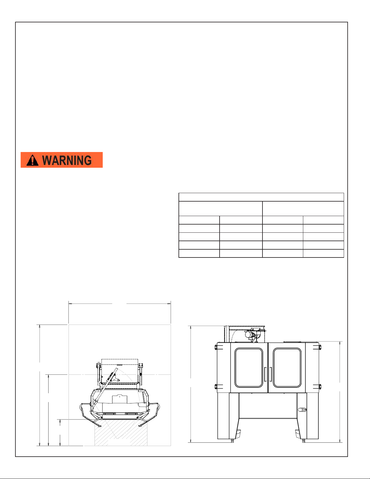
36"
[91CM]
165" [419 CM]
WORKSTATION
125
[318CM]
97"
[245CM]
OPERATOR &
LOAD AREA
AREA REQUIRED IF USING
THE OPTIONAL WORKSTATION
INSTALLATION INSTRUCTIONS
FIG. 2
70
[178 CM]
81
[206 CM]
REMOVE GRINDER FROM WOOD PALLET
THE UNIT WEIGHS 1450 LBS. [658 KG]. USE POWER EQUIPMENT
TO LIFT THE UNIT.
POSITION THE BASE
PLACING THE GRINDER ON FLOORING THAT IS NOT LEVEL OR BROKEN WILL AFFECT GRINDING
QUALITY.
MACHINE MUST BE POSITIONED TO ALLOW EASY ACCESS TO THE MAIN POWER CORD PLUG FOR USE
AS THE MAIN DISCONNECT. SEE POWER INSTALLATION SECTION FOR ADDITIONAL INFORMATION.
ELECTRICAL REQUIREMENTS:
• ALWAYS USE A PROPERLY GROUNDED OUTLET!
0-40 0-12 12 4.0
40-60 12-18 10 6.0
60-100 18-30 8 10.0
100-160 30-48 6 16.0
13
ORIGINAL INSTRUCTIONS
INSTALLATION INSTRUCTIONS
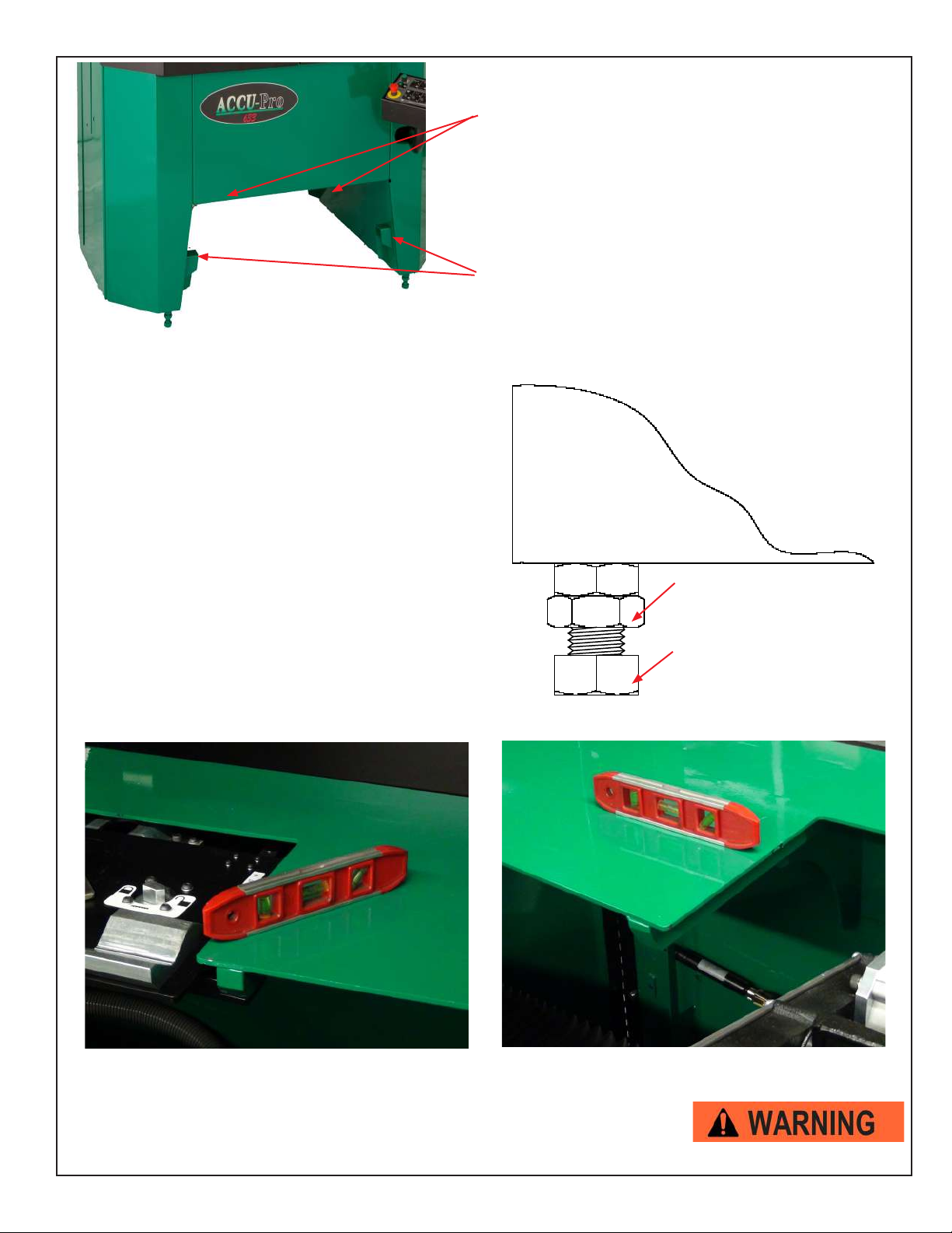
LEVEL BASE
See FIG. 5.
FIG. 4
FIG. 6FIG. 5
LOOSEN JAM NUT TO
ADJUST FOOT
LEVELING FEET LOCATED
THE EQUIPMENT SHOULD NEVER BE LEFT UNATTENDED WHEN RUNNING.
LIFTING LOCATION
FIG. 3
14
ORIGINAL INSTRUCTIONS
It is recommended that grinder has its own permanent power connecon from the power
distribuon panel, with no other major power draw equipment on the same line.
The grinder is equipped with a high-low voltage relay (LVR) which is factory preset at 100-140 V
ac. If the VOLTAGE INSIDE THE CONTROL PANEL FALLS OUTSIDE OF THE RANGE OF 100-140 V ac
power under load, the relay will open and trip out the starter. If this occurs, your power supply
line is INADEQUATE TO RUN THIS MACHINE and must be corrected before proceeding any further
with the grinder. If the oponal transformer is installed on the outside of the machine, the
power delivered to the machine will be 230 V ac, but the power in the machine must be 100-140
V ac under load as stated above.
DO NOT operate this grinder with an extension cord.
Do not operate this grinder on a Ground Fault interrupter (GFI) circuit. Nuisance tripping of the
(GFI) may occur.
PROPER GROUNDING OF THE RECEPTACLE GROUND IN YOUR BUILDING MUST BE VERIFIED.
IMPROPER GROUNDING IN YOUR BUILDING MAY CAUSE THE GRINDER TO MALFUNCTION.
POWER INSTALLATION
IF THE MACHINE DOES NOT HAVE A PLUG ON THE END OF THE MAIN POWER CORD, A PLUG OR
CONNECTOR THAT COMPLIES TO THE LOCAL LAWS AND REGULATIONS SHOULD BE INSTALLED BY A
QUALIFIED ELECTRICIAN. THE PLUG IS CLASSIFIED AS A CATEGORY 0 MAIN DISCONNECT. DO NOT
WIRE THIS MACHINE DIRECTLY TO A POWER SOURCE WITHOUT A PLUG OR CONNECTOR UNLESS
A DEVICE THAT MEETS THIS CATEGORY 0 MAIN DISCONNECT REQUIREMENT IS USED TO PROVIDE
POWER TO THE MACHINE.
IMPORTANT GROUNDING INSTRUCTIONS
In case of a malfuncon or breakdown, grounding reduces the risk of electrical shock by providing a path
of least resistance for electrical current.
This grinder has an electrical cord with an equipment grounding conductor and a grounding plug. The plug
must be plugged into a matching outlet that is properly installed and grounded according to all local or
other appropriate electrical codes and ordinances.
Before plugging in the grinder, make sure it will be connected to a supply circuit protected by a
properly-sized circuit breaker or fuse. SEE SERIAL NUMBER PLATE FOR FULL LOAD AMP RATING OF YOUR
MACHINE.
Never modify the plug provided with the machine--if it does not t the outlet, have a proper outlet and
circuit installed by a qualied electrician.
Always provide a proper electrical ground for your machine. An improper connecon can cause a
dangerous electrical shock. If you are unsure of the proper electrical grounding procedure, contact a
qualied electrician.
INSTALLATION INSTRUCTIONS

15
ORIGINAL INSTRUCTIONS
INSTALLATION INSTRUCTIONS
120 VOLT MODEL ONLY.
STANDARD PLUG FOR
FIG.7
230 V 50/60Hz MODEL
USE ONLY A QUALIFIED
ELECTRICIAN TO
COMPLETE THE
INSTALLATION.
FIG. 8
1. and
2. X3
A
3.
14 G. (2.5MM) GREEN
GROUNDWIRE TO BE
ADDED.
GROUND WIRE
GROUND WIRE
BROWN
NEUTRAL
BROWN
0-40 0-12 12 4.0
40-60 12-18 10 6.0
60-100 18-30 8 10.0
100-160 30-48 6 16.0

16
ORIGINAL INSTRUCTIONS
GETTING TO KNOW YOUR GRINDER
5. CONTROL
1.
2.
3.
4.
5. CONTROL
SYSTEMS
4. SPIN DRIVE
17
ORIGINAL INSTRUCTIONS
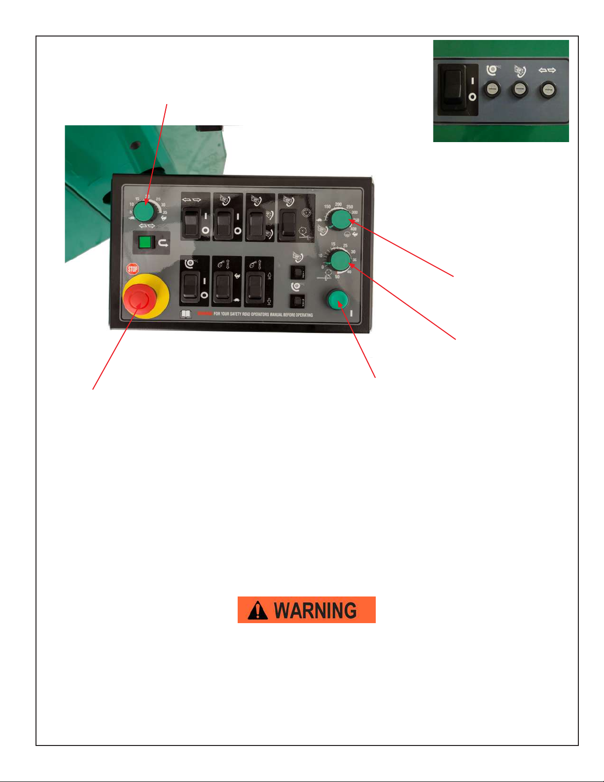
GETTING TO KNOW YOUR GRINDER
CONTROLS
2. START/RESET BUTTON
5. TORQUE
6. SPIN SPEED
1.
2. START/RESET BUTTON
3.
4.
THIS IS NOT A MAIN DISCONNECT!
5.
6.

18
ORIGINAL INSTRUCTIONS
OPERATION
the E-STOP BUTTON
RESET BUTTON.
RELIEF ANGLE DECAL
RELIEF ANGLE
ADJUSTER
REEL POSITIONER
RELIEF ANGLE ADJUSTER. NOTE: The pre-posioned sengs
do not work for walking greens mowers with a rear drum only. SEE PAGE 38.
RELIEF ANGLE.
STEP 1: PLACING THE CUTTING UNIT
PREPARE CUTTING UNIT
1.
2.
3.
4.
12° angle
Example: If your reel is a 7" Jacobsen reel you will set the ACCU-REEL POSITIONER as shown above and
the relief will be set to the corresponding 12° angle as shown in the picture to the right. If the reel you are
grinding does not t these parameters see Page 38.

19
ORIGINAL INSTRUCTIONS
OPERATION-WINCH
FRONT ELECTRIC BOOM LOADING
REAR ELECTRIC BOOM OPTION
LIFTING OPTIONS
LIFTING A REEL INTO POSITION
OPTIONAL BOOM WITH ELECTRIC WINCH
1.
2.
OPTIONAL ELECTRIC WINCH
OPTIONAL WORKSTATION - Can be used to load from the
rear on both the ACCU-Master and the ACCU-Pro Grinders.

20
ORIGINAL INSTRUCTIONS
OPERATION
Read carefully before aempng to operate or service your oponal electric winch or oponal
Workstaon! Failure to comply with instrucons could result in personal injury and/or property damage!
FOR YOUR OWN SAFETY AND THAT OF OTHERS, THIS EQUIPMENT MUST BE USED AS RECOMMENDED BY
THE MANUFACTURER. FAILURE TO HEED THE FOLLOWING RECOMMENDATIONS COULD ENDANGER YOUR
LIFE.
DO NOT ATTEMPT TO
MOVE LOADS GREATER THAN THIS RATINGS.
2. NEVER CARRY
3. NEVER MOVE A LOAD
4. DO NOT ALLOW
5. KEEP CLEAR OF RAMP OR WINCH WIRE ROPE AND
HOOK WHEN OPERATING. DO NOT ATTEMPT to
6. AVOID
7. BE SURE
8. DO NOT OPERATE
9. KEEP WORKSTATION/WINCHING AREA CLEAR.
11. ALLOW WORKSTATION/WINCH TO COOL
DOWN FREQUENTLY
12. DO NOT OPERATE WORKSTATION/WINCH WHEN
UNDER THE INFLUENCE OF DRUGS, ALCOHOL, OR
MEDICATION.
13. DO NOT USE WORKSTATION/WINCH TO HOLD
LOADS IN PLACE
14. USE ONLY FACTORY APPROVED SWITCHES,
REMOTE CONTROLS AND ACCESSORIES.
15. DO NOT MACHINE OR WELD ANY PART OF THE
WORKSTATION/WINCH
16. DO NOT OPERATE THIS WORKSTATION/WINCH
OUT DOORS OR IN A CORROSIVE OR EXPLOSIVE
ENVIRONMENT.
NOTE: THE FOLLOWING APPLY TO OPERATION OF
THE WINCH ONLY.
1. MAINTAIN A MINIMUM OF 4 TURNS OF WIRE
ROPE
2. WHEN SPREADER BAR ASSEMBLY IS USED
3. NEVER HOOK THE WIRE ROPE BACK ON ITSELF.
USE THE SPREADER BAR ASSEMBLY.
4. DO NOT
5. NEVER TOUCH
6. INSPECT WIRE ROPE FREQUENTLY
7. USE HEAVY LEATHER GLOVES
Table of contents
Other Foley United Grinder manuals


Popular Grinder manuals by other brands


Meterk
Meterk S1M-GW20-115 Translation of the original instructions

U.S.SAWS
U.S.SAWS SX65000C operating manual

Parkside
Parkside PWS 230 C3 Translation of the original instructions

SUHNER ABRASIVE
SUHNER ABRASIVE ASC 9 Technical document

PTA
PTA P1322 Operation manual

Craftsman
Craftsman CMCG400 instruction manual


