GRINDINGCHISELCHAIN
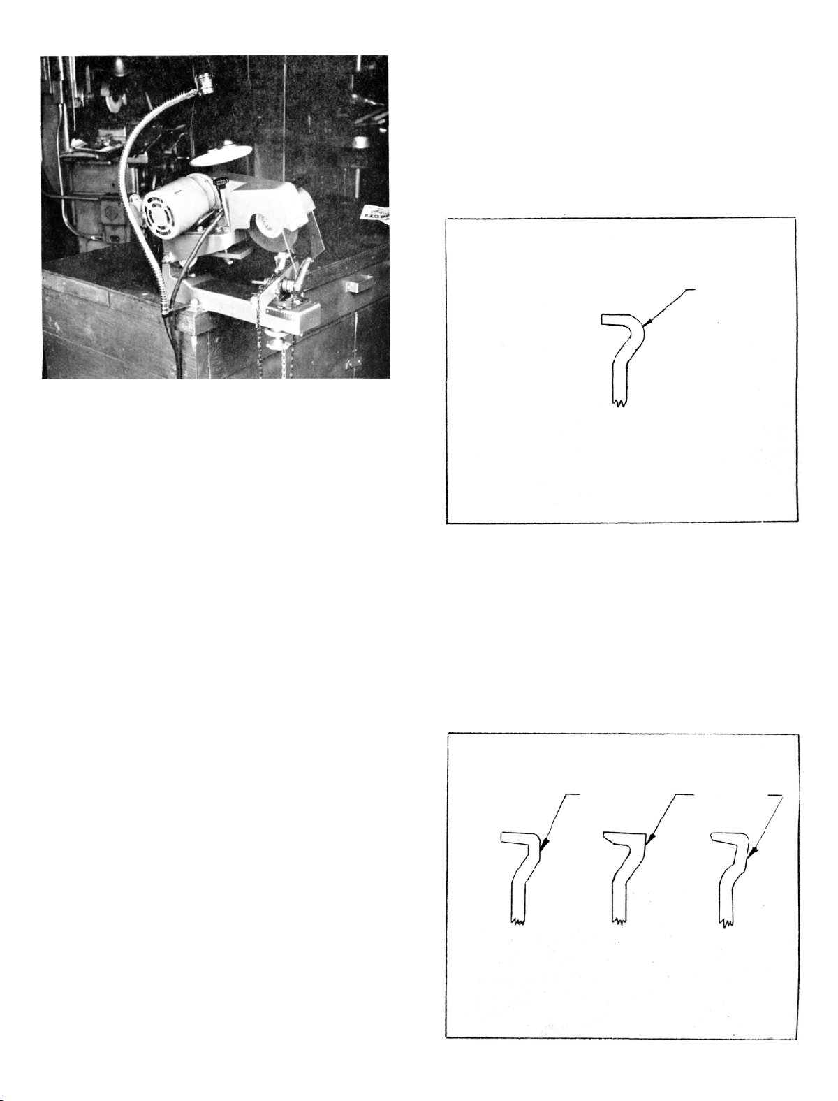
1.Chooseanddressthegrindingwheelasexplained
earlier.RefertoIllustrationNo.2 forcorrectly
groundchiselcutter.
2.Placechaininchainvisewiththecuttingedges
facingtotheleft.
3.Tiltthegrindingheadto30°andlock.
4.Setandlockchainviseat30°totheleft(rotating
clockwisefrom0°).SeeIllustrationNo.4.
5.Slidethechainvisebackandlockiton1½onthe
horizontalscale.
6.Positionthestopfingerbehindtherighthandcut-
tertobegroundandalignthetoothtothewheel.
Setthedepthstop.
7.Turnthemotorswitchto"Forward"position
(counterclockwiserotationwhenviewedfrom
wheelendofshaft)andadjustthestopfingerfor
thelightestgrindingpassthatwillsharpenthe
toothproperly.Grindallrighthandcutterswith-
outchangingyoursetup.
8.Slidethechainviseforwardandlockat1½on
horizontalscale.
9.Rotatethechainviserightandlockat30°.See
IllustrationNo.4.
10.Positionthestopfingerbehindthelefthandcutter
tobegroundandalignthetoothtothegrinding
wheel.Changeonlythestopfingerpositionif
necessary.
11.Grindalllefthandcutterswiththemotorswitch
inthe"Reverse"position.
12.Checkandgrinddepthgaugesifnecessary.See
IllustrationNo.11underGrindingChipperChain.
OREGON#80SERIESCHAIN
1.Usea 5/16"thickwheelwitha straightface.Faceof
thegrindingwheelmustbe90°tothesidesofthe
wheel.
2.Placechainintochainviseandpositionstopfinger
behinda right-handcutter.
3.Thechainviseshouldbesetat0°onthescaleand
the0 positiononthehorizontalscale.Grinding
wheelshouldbesetat10°rightonthegrindinghead
scale.
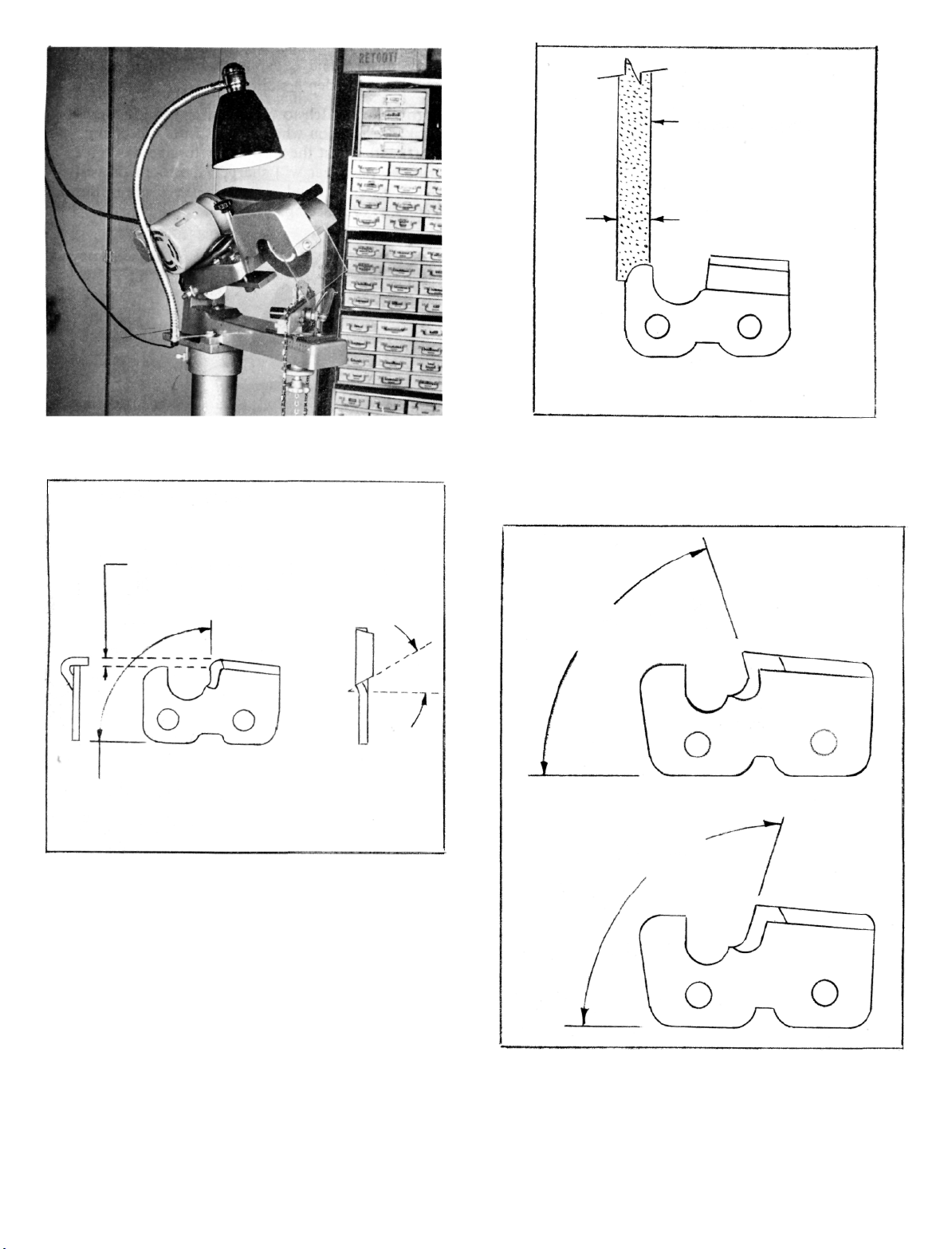
Grindthetopsofallrightandleftcuttersthesame
height.
IllustrationNo.9
4.Togrinddepthgauges,setthestopfingerbehinda
righthandcutter.Setthewheelto15°leftonthe
grindingheadscale.Movethechainvisetoposi-
tionthedepthgaugedirectlyunderthewheeland
grindalloftherighthanddepthgauges.020lower
thanthetipsofthecutters.Setthestopfingerbehind
alefthandcutter.Positionthelefthanddepthgauge
underwheelandgrindalllefthandgauges.Leave
grindingheadat15°left.
5.Grindingfacesofcutters(notrequiredeverysharp-
eningunlesschainhasbeendamagedorisextremely
dull).Dress3/16"thickwheelroundtofittheradius
gauge.Chainbarsetat0°positiononthesidescale
andat22°totheleft(clockwisefrom0°)onthe
chainvisescale.
Setthegrindingheadat22°andgrindallrighthand
cutters.
6.Swingthechainvisetotherightandlockat22°.
Grindallofthelefthandcutters.
ADJUSTMENT-CHAINVISE
Theopeningandclampingrangeofthechainviseis
controlledbythetwo3/8nutsontheviseshaftand
leverassembly.
Backofftheouterlocknut.Adjusttheviseopening
withtheinnernutwhileholdingtheviseleverinthe
properpositiontoprovidefulltravel— locktounlock.
Holdtheinnernutinplaceandtightenthelocknut.
Page6
.020 22°BEVEL
22°HOOK
15°
10°
OREGON80CHAIN