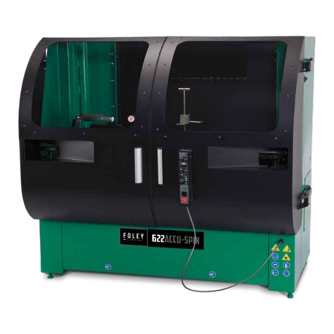
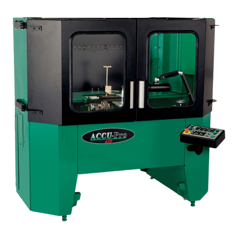
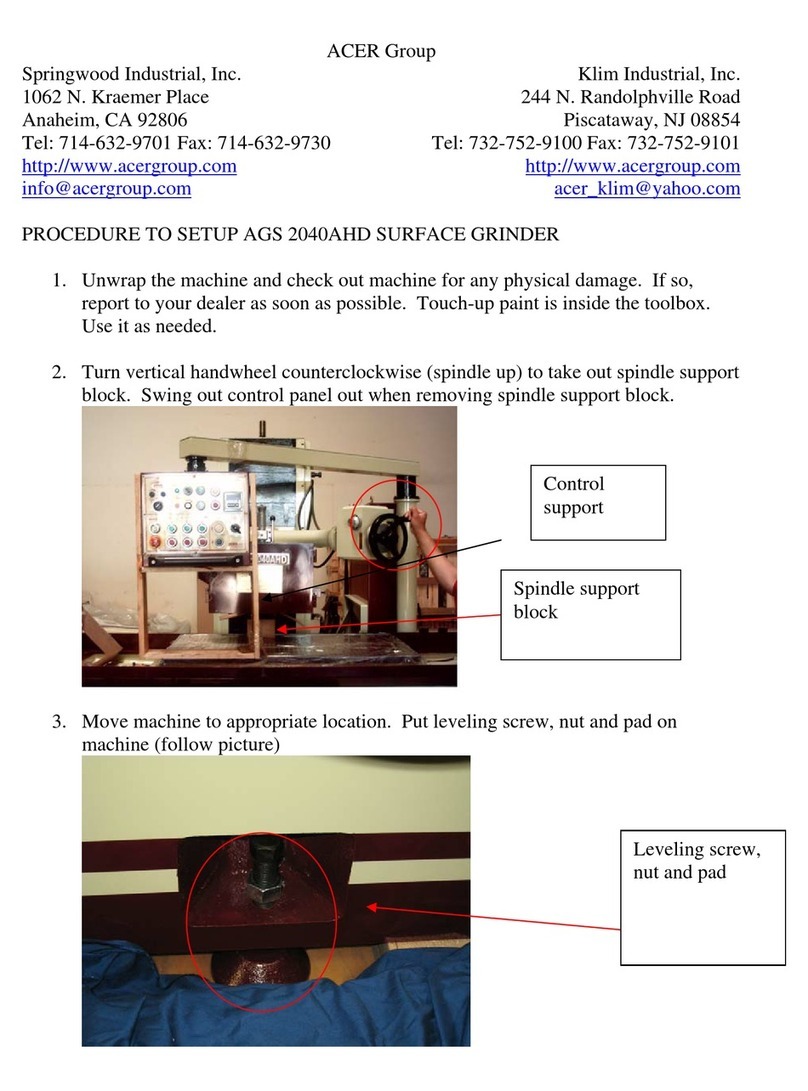
Foley 3096 Operating instructions

1
Model 3096
Accu-Spin Reel
Mower Grinder
Maintenance
Troubleshooting
Adjustments
And Parts Lists
WARNING
You must thoroughly read and understand this manual
before operating the equipment, paying particular
attention to the Warning & Safety instructions.
3967922 (7-91)

2
SAFETY INSTRUCTIONS
1. KEEP GUARDS IN PLACE and in working order.
2. REMOVE ADJUSTING KEYS AND WRENCHES.
.
3. KEEP WORK AREA CLEAN.
4. DON'T USE IN DANGEROUS ENVIRONMENT.
Don't use power tools in damp or wet locations, or
expose them to rain. Keep work area well lighted.
5. KEEP ALL VISITORS AWAY. All visitors should be
kept a safe distance from work area.
6. MAKE WORKSHOP CHILD-PROOF. With padlocks
or master switches.
7. DON'T FORCE THE GRINDER. It will do the
j ob better and safer if used as specified in this manual.
8. USE THE RIGHT TOOL. Don't force the grinder
or an attachment to do a job for which it was not
designed.
9. WEAR PROPER APPAREL. Wear no loose clothing,
gloves, neckties, or jewelry which may get caught in
moving parts. Nonslip foot wear is recommended.
Wear protective hair covering to contain long hair.
10. ALWAYS USE SAFETY GLASSES.
11. SECURE WORK. Mount the cutting unit in place
before grinding as prescribed in the operators
manual.
12. DO NOT OVERREACH. Keep proper footing and
balance at all times.
13. MAINTAIN GRINDER WITH CARE.
Follow instructions in Service Manual for
lubrication and preventive maintenance.
14. DISCONNECT POWER BEFORE SEVICING.
15. REDUCE RISK OF UNINTENTIONAL
STARTING. Make sure switch is in OFF
position before plugging in the grinder.
16. USE RECOMMENDED ACCESSORIES.
Consult the manual for recommended
accessories. Using improper accessories may
cause risk of personal injury.
17. CHECK DAMAGED PARTS. A guard or other
part that is damaged or will not perform its
intended function, should be properly repaired or
replaced.
18. NEVER LEAVE GRINDER RUNNING
UNATTENDED. TURN POWER OFF. Do not
leave back lapper until it comes to a complete
stop.
19. KNOW YOUR EQUIPMENT. Read this manual
carefully. Learn its application and limitations as
well as specified potential hazards.
20. KEEP ALL SAFETY DECALS CLEAN &
LEGIBLE. If safety decals become damaged or
illegible for any reason, replace immediately.
Refer to replacement parts illustrations in
Service Manual for the proper location and part
numbers of safety decals.
21. DO NOT OPERATE THE GRINDER
WHEN UNDER the influence of drugs, alcohol,
or medication.
The Warning Symbol identifies special
instructions or procedures which, if not
correctly followed, could result in personal
injury, or loss of life.
The Caution Symbol identifies special
instructions or procedures which, if not strictly
observed, could result in damage to, or
destruction of equipment.
Safety Awareness Symbols are inserted in this
manual to alert you to possible Safety Hazards.
Whenever you see these symbols, follow their
Instructions

3
SAFETY INSTRUCTIONS
Grinding is a safe operation if the few basic rules listed below are followed. These
rules are based on material contained in the ANSI B7.1 Safety Code for "Use, Care
and Protection of Abrasive Wheels". For your safety, we suggest you benefit from the
experience of others and follow these rules.
DO
1. DO always HANDLE AND STORE
wheels in a careful manner.
2. DO VISUALLY INSPECT all wheels before
mounting for possible damage.
3. DO CHECK MACHINE SPEED against the
established maximum safe operating speed
marked on wheel.
4. DO CHECK MOUNTING FLANGES for
equal and correct diameter.
5. DO USE MOUNTING BLOTTERS when
supplied with wheels.
6. DO be sure WORK REST is properly
adjusted.
7. DO always USE A SAFETY GUARD
COVERING at least one-half of the grinding
wheel.
8. DO allow NEWLY MOUNTED WHEELS to
run at operating speed, with guard in place,
for at least one minute before grinding.
9. DO always WEAR SAFETY GLASSES or
some type of eye protection when grinding.
DON'T
1. DON'T use a cracked wheel or one that HAS
BEEN DROPPED or has become damaged.
2. DON'T FORCE a wheel onto the machine
OR ALTER the size of the mounting hole--if
wheel won't fit the machine, get one that will.
3. DON'T ever EXCEED MAXIMUM
OPERATING SPEED established for the
wheel.
4. DON'T use mounting flanges on which the
bearing surfaces ARE NOT CLEAN, FLAT
AND FREE OF BURS.
5. DON'T TIGHTEN the mounting nut
EXCESSIVELY.
6. DON'T grind on the SIDE OF THE WHEEL
(see Safety Code B7.2 for exception).
7. DON'T start the machine until the WHEEL
GUARD IS IN PLACE.
8. DON'T JAM work into the wheel.
9. DON'T STAND DIRECTLY IN FRONT of a
grinding wheel whenever a grinder is started.
10. DON'T FORCE GRINDING so that motor
slows noticeably or work gets hot.
AVOID INHALATION OF DUST generated by grinding and cutting operations.
Exposure to dust may cause respiratory ailments. Use approved NIOSH or MSHA
respirators, safety glasses or face shields, and protective clothing. Provide
adequate ventilation to eliminate dust, or to maintain dust level below the
Threshold Limit Value for nuisance dust as classified by OSHA.
IMPROPER USE OF GRINDING WHEEL MAY CAUSE
BREAKAGE AND SERIOUS INJURY.
21. DO NOT OPERATE THE GRINDER

4
TABLE OF CONTENTS
TABLE OF CONTENTS
Maintenance & Lubrication…………………………… 4
Adjustments……………………………………………. 5-9
Troubleshooting……………………………………….. 10-23
Parts Lists & Exploded Views……………………….. 24-37

5
MAINTENANCE & LUBRICATION
MAINTENANCE
1. Clean excess dirt and grit from machine daily.
2. Wipe off the auto traverse drive shaft daily./
3. Carriage front rail boots should be lifted and
wiped off daily.
4. Replace the two (externaly) foam rail wipers
every 20 hours of operation.
5. Check all fastening bolts monthly to be sure
they are tight.
6. Check gib plate adjustment in the grinder car-
riage base monthly.
7. Check the brushes on the auto traverse drive
motor once a year. Replace as necessary.
LUBRICATION OF ACTUATOR AND
LINEAR BEARINGS
STEP 1– Thoroughly clean all three shafts and
seals. If you have compressed air available, blow
off the shafts, carriage, seals, grinder base, etc.
NOTE: Always point the compressed air nozzle
away from the seals bearings to insure you do not
drive foreign material into the bearings. Then
wipe off the shafts and seals and blow off a
second time. If you do not have compressed air,
then thoroughly wipe off the shafts and seals. As
part of this cleaning the carriage should be trav-
ersed several times to insure all areas are clean.
STEP 2- Flood spray all three shafts with either
WD40 or Tri-Flow Lubricant or our lubricant part
No. 3708201, until the lubricant is dripping off the
shafts. Then run the carriage black and forth
through its range of travel. This will carry the
lubricant into the actuator and bearings.
NOTE: Because of the flood of lubricant you may
find that the actuator slips and traversing is erratic
or stalls. This is not a problem as it will be cor-
rected in the subsequent steps.
STEP 3- With a clean rag, wipe off the excess
amount of lubricant from the shafts. Run the
carriage back and forth through its range of travel
and wipe the shafts after each traverse. Repeat
until the shaft are dry to the feel. This completes
the lubrication process.
LUBRICATION FREQUENCY
The lubrication frequency should be every four
hours of grinder operation or more often if a
squeaking noise is coming from the linear
actuator. If the unit will be shut down for an
extended period of time, more than two weeks,
then the shafts and other appropriate parts of
the unit should be flooded with lubricant and that
lubricant left in place until the unit is brought
back into service. When the unit is brought back
into service the full lubrication procedure as
stated above should be repeated.
Fig. 1
Fig. 2

6
ADJUSTMENT:
LINEAR ACTUATOR ADJUSTMENT & BEARING REPLACEMENT
LINEAR ACTUATOR BEARING REPLACEMENT
STEP 1- Unscrew the pin driver (item 2) that passes through the
self aligning bearing, (item 38) in the carriage (item 11) and unscrew
where it is threaded in to the actuator block (fig. 3). Slide the car-
riage off to one side to expose the actuator.
STEP 2- Turn the actuator screw (item 25) as much as required
clockwise to disengage the bearings from the drive shaft so it moves
freely.
STEP 3- Remove the two outboard seal mounts (item 31).
STEP 4- Remove shoulder bolts (fig. 4) fastening the bearings
(item 41) to the actuator block (item 29). Remove the old bearings
and discard, saving the inside washer (fig. 4). Inspect the hole that
the bearing and shoulder bolt were removed from and the actuator
bore for foreign material. If any is observed, thoroughly clean.
Insert the shoulder bolt through the new bearings and through the
saved inside washer. Then install this assembly into the actuator
and tighten the shoulder bolts.
STEP 5- Turn actuator screw (item 25) counterclockwise until all 6
bearings are in contact with the drive shaft (item 24). The actuator
screw washer (item 27) should be 1/32” clear of the outboard screw
heads. (see fig 4)
STEP 6– Remount the outboard seal mounts (item 31) making sure
the seal is concentric to the carriage drive shaft (item 24). Also
square up the seal mount blocks (item 31) to the actuator block
(item 29) within 1/32”.
STEP 7- Slide the carriage (item 11) over the actuator block (item
29) to line up the hole in the carriage with the tapped hole in
actuator. Insert the pin driver (item 2) through self aligning bearings
(item 38) and tighten.
STEP 8- Using a spring scale, set the scale up to pull on the
carriage parallel to actuator drive shaft (item 24). Then while
holding the drive shaft from rotating, pull on carriage; the pull force
should be from 15 lbs. To 45 lbs., target 30 lbs. Force. (See step 9
for readjustment if necessary).
STEP 9- If readjustment is required to achieve pull force within
specification, with actuator bearings engaged to drive shaft,
readjust the two outboard screws with springs (fig. 4) that hold the
actuator together. To reach these screws, the actuator screw,
washer and spring must be removed. Turn each screw an equal
amount when resetting for more or less tension, clockwise is more
tension. Repeat Step 8 and verify pull force. Continue to adjust
until within specification. The factory preadjusted tension is 9/32”
from under the washer holding the spring to the actuator block.
This should give the 15 to 45 lbs. Carriage pull force specified.
When adjustment is correct reinstall the actuator screw (fig. 3 item
25) with its spring (fig. 3 item 28) and flatwasher (fig. 3 item 27)
and tighten to within 1/32” of the outboard screw heads.
The pull force is to be checked when shaft is
wiped clean and dry. If checked when oily, too
much tension will be set and affect bearing
life.
If the actuator screw is tightened too much, it
will contact the outboard screw heads and
override their adjustment which could cause
traverse malfunction. Always maintain the
1/32” gap except when purposefully overriding
per Step 2 above.
Overtightening of actuator above the 45 lbs.
Maximum will not improve drive performance.
It will only shorten the bearing life.
Fig. 3
Fig. 4

7
ADJUSTMENT:
CARRIAGE LINEAR BEARING ADJUSTMENT & REPLACEMENT
CARRIAGE LINEAR BEARING REPLACEMENT
STEP 1- Loosen & remove the limit switch bracket
(item 17, fig. 3) and place it as the electrical lead will
allow. Unplug the electrical lead from the motor and
place it to one side.
On the 3096 model only, release all spring tension by
removing the horizontal adjusting screw assembly. On
the 3096 model only, remove the rubber boots from
both sides of the carriage on the front shaft. (see fig.
5)
Remove pin driver (item 2, fig. 3) from linear actuator
(item 29, fig. 3). Then remove the screws (item 33, fig.
6) from the front and rear carriage shafts. Then slide
the carriage assembly to the right end of the carriage
shafts (fig. 6) Lift eh carriage assembly and carriage
shafts (fig. 6), slide the carriage assembly to the right
off first the rear carriage shaft and ten off the front
shaft. The shafts must be gripped by hand and pulled
left while the carriage assembly is moved right. After
removing the carriage assembly, lay it on its side on
the floor.
STEP 2- Remove the 3 linear bearing pillow blocks
(item 12, fig. 6) and discard.
STEP 3- Insert the three new linear bearing pillow
blocks (item 12, fig. 6). Adjust the tension screw on
the side of each bearing block so when you radially
rotate the pillow block around the carriage shaft there
should be no free play between bearing (item 12, fig.
6) and carriage shaft (item 42, fig. 6). Repeat this
adjustment to all three pillow blocks and then remove
the pillow blocks from the carriage shaft.
NOTE: Tension is too tight if you feel a cogging action
when you rotate pillow block around the shaft. This
cogging is from the skidding of the bearing on the shaft
and indicates tension screw is too tight. As a final
check, sliding the bearing back and forth on the shaft
should be a smooth uniform motion.
The carriage assembly weighs
approximately 40 lbs. Be prepared to
handle the weight or get assistance in
handeling.
Setting the bearing tension correctly is
critical to proper grinding. Bearings which
are too tight or too loose will cause poor
grind quality. Also, bearings which are too
tight will have a substantially shortened life
and will damage the shaft
Fig. 5
Fig. 6

8
ADJUSTMENT:
CARRIAGE LINEAR BEARING ADJUSTMENT & REPLACEMENT
STEP 4- Assemble the three linear bearing pillow
blocks (item 12, fig. 6) loosely to carriage (item
11, fig. 6) with the tension adjustment screws
pointing outward. Insert the previously cleaned
carriage shaft (item 42, fig. 6) thru the front two
linear bearing pillow blocks and align them to
each other with a straight edge underneath the
carriage and tighten down the socket head screws
(item 13, fig. 6). Lift the carriage assembly back
onto the main grinder base and solidly bolt down
the front carriage shaft (item 42, fig. 6) with
screws (item 33, fig. 6).
On the 3096 model only, attach a center screw
into the carriage shaft loosely, then attach the
horizontal adjusting springs to the carriage shaft
and install and tighten the screws.
STEP 5- To set the distance between the front
pillow blocks, already tight, and the rear pillow
block, slide the rear carriage shafts thru the pillow
block and position it into its “V” groove bosses.
Tighten the 2 socket head screws (item 13, fig. 6)
visible from the rear on pillow block (item 12, fig.
6). Raise rear carriage shaft and carriage,
position the carriage between V-groove bosses on
the main base (item 31, fig. 6) and tighten the
other 2 socket head screws. Lower and bolt down
the rear carriage shaft (item 42, fig. 6) solidly in
the “V” grooves bosses with screws (item 33, fig.
6). The bearing tension is correct when you try to
lift the carriage and can feel no carriage
movement, free play up and down. Also, when
pulling the carriage in the traversing direction,
there should be only approximately a 3 lb. force
using a scale system similar to Step 8 of Linear
Actuator Bearing Replacement. To double check
the assembly, slide the carriage assembly from
“end of travel” to “end of travel,” it should have
very uniform resistance through the full range of
travel. When bearing tension is correct, reinstall
linear actuator pin driver (item 2 fig. 5).
STEP 6- Reinstall the limit switch bracket and
reconnect the electrical lead to the motor. On the
3096 model only, reinstall the rubber boots on the
front shaft and reinstall the horizontal adjusting
screw assembly (see fig. 5).
Fig. 7

9
ADJUSTMENTS
ALIGN FRONT RAIL & DRIVE SHAFT
The front rail and drive shaft need to be perfectly
aligned (± .010). The adjustment is made by
loosening the drive shaft support blocks and
aligning the shaft to the front rail to within ± .010.
When alignment has been completed, tighten
the drive shaft support blocks.
Also refer to the Troubleshooting section, Items
J & K-
Problem- Reel ground in a concave, convex
shape or irregular shape.
GIB ADJUSTMENT
It is very important to have the gib adjustment
tight, so as not to have any play while grinding.
Refer to the Troubleshooting section Item H-
Problem- Reel ground in a concave, convex
shape or irregular shape.
Fig. 8
Fig. 9

10
ADJUSTMENTS
CONTROL BOARD SETTINGS- The control board adjusting knobs inside the control box should
be set as follows:
Min. Speed (Minimum Speed)- Allows adjustment of the motor speed when the main speed knob is
set at minimum. This permits the user to eliminate the “Dead Band” on the main speed control
permitting zero calibration. Clockwise rotation of “MIN,” trim pot increases speed. This trim pot allows
for adjustment of 30% of maximum speed.
ACC. (Acceleration)- Allows adjustment of the motor acceleration form a minimum of .2 seconds to
10 seconds maximum.
DECEL. (Deceleration)- Permits adjustments of the motor deceleration from a minimum of 1 second
to 10 seconds maximum.
MAX. SPEED (Maximum Speed)- Provides for adjustment of the motor speed when the main speed
knob is set a maximum. This permits the user to eliminate the “Dead Band” on the main speed
control to have full speed at maximum rotation. Rotation of “MAX,” trim pot in the clockwise direction
increases maximum motor speed. The “MAX” trim pot allows for adjustment of 70% of base speed.
I.R. COMP (Speed Regulation)- This allows for adjustment of the circuitry that controls the speed
regulation of the motor. The circuitry controls armature voltage by changing the armature voltage to
compensate for increased or decreased motor loading. Clockwise rotation of “I.R. COMP” trim pot will
increase compensation. 1) Set SPEED control pot at 50%. 2) Turn IR COMP pot CW until motor
begins to hunt. 3) Turn IR COMP pot CCW until hunting stops. 4) Set IR Comp pot 1/3 of the span
between where motor hunting stopped & fully CCW position.
CUR. LIM. (Current Limit)- Provides protection form excessive armature current by limiting the
maximum torque the motor can deliver. Torque adjustment (CUR. LIM.) is preset at 125% of rated
motor torque (Current) based on horsepower. Clockwise rotation of “CUR. LIM.” pot increases the
torque (Current) the control will provide. This control is adjustable to 200% of rated motor torque.
THESE SETTINGS ARE PRESET AT FACTORY.
MOVE ONLY AFTER CONSULTING WITH
FACTORY.
NOTE: The only two settings that ever need to be
adjusted are the acceleration dial and the IR comp
dial. Consult factory before adjusting any of these
dials.
The manufacturer recommends
that the maximum speed be set
no higher than shown for safety
considerations.
Alteration of Current Limit could
damage the motor.
LIMIT SWITCH ADJUSTMENT
When the switch (#20) is riding on the high side
of the shaft (#17), it should be actuated by
only .005 to .010”. It is actuated when you hear
a click inside.
With the actuator slide rod (.50 diameter) over
the limit switch plunger, adjust the limit switch
until you hear a click, then go .005/.010 farther
for additional travel.
Fig. 11

11
TROUBLESHOOTING:
Electrical controls, wiring, linear actuator, carriage system and DC drive system.
PROBLEM-
Insufficient
hesitation at
carriage stops prior
to reversing
POSSIBLE CAUSE-
Acceleration pot inside
control panel on the main
control board set to low.
REMEDY-
Remove the sheet metal front cover on the control panel. On
the printed circuit board turn the dial marked “accel”
clockwise to increase delay time. Adjust for a 1-second delay
prior to reversing. (For more detail see the control board
settings in the adjustment section of the manual.)
REASON-
Accel pot controls acceleration
time and hesitation time before
reversing.
POSSIBLE CAUSE-
A-Limit switch actuator
slide is inserted wrong.
(Only if the actuator slide
rod was removed.)
REMEDY-
The slide is not symmetrical and can be installed incorrectly.
The actuator rod is to have the side with the 4” long x .50”
diameter (from one end to center groove) side located on the
right hand side when looking from operator position at the
limit switch bracket for 3096. On the 3084 and 3055, the 4”
long x .50 “ diameter is to be mounted on the left hand side
REASON-
Installation positioning required
for proper mechanical actuation
of limit switch and wiring
hookup. (DC motor to circuit
board controls direction of
reversing.) When slide rod is
inserted wrong the traverse will
only travel in one direction and
will not reverse.
POSSIBLE CAUSE-
B- Limit switch stays
unactivated.
REMEDY-
With the actuator slide rod (.50 diameter) over the limit switch
plunger. Adjust the limit switch until you hear a click then
go .005/.010 farther for additional travel. (For more detail see
limit switch in the adjustment section of he manual.)
REASON-
The limit switch slide rod is
improperly adjusted and does
not actuate the limit switch to
reverse the traverse direction.
The .005/.010 plunger over
travel permits actuation.
PROBLEM-
Carriage
traverse will not
reverse
direction.

12
TROUBLESHOOTING:
Electrical controls, wiring, linear actuator, carriage system and DC drive system.
POSSIBLE CAUSE-
C- Limit switch plunger is
jammed.
REMEDY-
Loosen the limit switch and free up the plunger manually, then with
the actuator slide rod large .50” diameter over the limit switch
plunger, adjust eh limit switch until you hear a click, then go
005/.010 farther for additional travel. (For more information see
limit switch in the adjustment section of the manual.)
REASON-
The limit switch has moved,
causing the actuator plunger to be
jammed in retracted position only.
This causes only one way
actuation so the traverse will not
reverse direction.
POSSIBLE CAUSE-
D– Limit switch is bad.
REMEDY-
Check continuity of the limit switch by unplugging limit switch from
the main box outlet. Next, remove limit switch wires from the main
circuit board. Use ohm meter for this step.
First, measure continuity between the red and white (common)
wire and check to see if make (switch closed) has continuity and
break (switch open) has no continuity when actuation the limit
switch.
Second, measure continuity between the black wire to white
(common) wire and check to see if make (switch closed) has
continuity and break (switch open) has no
continuity when actuating the limit switch. If not, replace switch.
using ohm meter an open circuit (switch open) reads “0” ohms-
closed circuit (switch closed) ohms reads full scale.
REASON-
When one set of contacts are bad,
the carriage will not reverse,
allowing it to go in the opposite
direction.
PROBLEM-
Carriage traverse will
not reverse
direction.
POSSIBLE CAUSE-
E– The reversing control
board is bad.
REMEDY-
First, check limit switch operation (shown in Step D) before this
step. With limit switch activated on large .50” slide diameter, first
check 90 volts to DC motor at circuit board from +A or (A!) terminal
to –A or (A2) terminal with a voltmeter.
NOTE: The voltage meter connection leads to terminal +A & -A
will have to be switched when going from the high side (large
diameter) of slide rod (switch activated) to groove side (small
diameter of slide rod) (switch inactivated) to get a voltage reading
to the DC motor because DC voltage changes polarity to reverse
motor directions.
Second, with limit switch in the groove location (switch
Inactivated) check for 90 volts to DC motor at circuit board from +A
or (A1) terminal to –A or (A2) terminal with a
voltmeter. If not, replace board.
The voltage varies with speed
REASON-
To check the circuit board is
working to drive motor in both
directions.
PROBLEM-
Carriage traverse will
not reverse
direction.

13
TROUBLESHOOTING:
Electrical controls, wiring, linear actuator, carriage system and DC drive system.
POSSIBLE CAUSE-
A– No voltage going to
motor.
REMEDY-
Check for 90 volt DC at the circuit board leads going to the
motor. Across terminal +A or (A1) and –A or (A2), check
reading with a voltage meter. When there is voltage from the
circuit board but DC motor does not run, check wiring and
plug connection. When there is voltage form circuit board,
remove the brush holder caps and crushes from the motor.
The voltage varies with speed pot setting.
REASON-
This checks to see that voltage
is getting from circuit board
only. Check the voltage across
the two brush holders. This is
to assure voltage is all the way
to DC motor. (Note: Brushes
are long life and very seldom
need replacement.)
POSSIBLE CAUSE-
B– Brushes in motor may
be worn out.
REMEDY-
Remove the brushes one at a time and maintain orientation
for reinsertion. See if brush is worn short 3/8 (.375) minimum
length, and look at wear pattern on commutator for arcing.
Replace brush if necessary.
REASON-
A short brush does not make
an adequate electrical
connection to run the electrical
motor.
POSSIBLE CAUSE-
C- Blown fuse.
REMEDY-
Replace the fuse and decrease stock removal rate.
REASON-
Extremely heavy grinding cuts
cause excessive loading of the
motor.
Replace actuator bearings if they are worn and do not rotate
freely. (For more detail see actuator maintenance in the ad-
justment section of the manual.)
Worn and binding actuators
causes heavy loading to motor.
Replace the linear bearings in the main carriage. Carriage
should traverse freely with a 3 lb. Maximum loading. Also
check for excessive bearing preload. (For more detail see
carriage bearing replacement in the adjustment section of the
manual.)
Grinding grit over a period of
time does get into the linear
bearings and causes excessive
drive torque of carriage.
PROBLEM-
DC traverse motor
does not work. .

14
TROUBLESHOOTING:
Electrical controls, wiring, linear actuator, carriage system and DC drive system.
PROBLEM-
Carriage traversing
(varies speed)
while grinding.
POSSIBLE CAUSE-
A- Oil on carriage drive
shaft..
REMEDY-
Wipe oil completely from shaft.
REASON-
Driving torque is lost because
the oil decreasing friction for
driving linear actuator.
POSSIBLE CAUSE-
B– Linear actuator does
not have sufficient tension
to shaft.
REMEDY-
1. Release linear actuator override screw to permit full
2. driving torque.
3. Increase spring pressure on linear actuator if below f
4. actory minimum of 15 lbs. Target tension is 30 lbs. (For
more detail see linear actuator bearing replacement in the
adjustment section of the manual).
REASON-
Sufficient spring tension on
linear actuator bearings is
required for driving of the
carriage.
POSSIBLE CAUSE-
C- Linear actuator
bearings have developed
flat spots.
REMEDY-
When the linear actuator spring pressure is set too high, you
can flat spot the actuator bearings. Back off the spring
tension to manual specifications. Factory preset range is
15-45 lbs. Pull. Target tension is 30 lbs. Replace all
bearings. (For more detail see bearing replacement in
adjustment section of the manual.)
REASON-
Too high a spring pressure in
linear actuator causes
excessive bearing loading.
This causes bearings to be
overloaded and not rotate
freely under a grinding load.
Bearings then skid and create
flat spots.
PROBLEM-
Carriage
traverse will not
reverse
direction.
POSSIBLE CAUSE-
D- Linear bearings in
carriage do not rotate
freely.
REMEDY-
Replace the linear bearings in the main carriage. (For more
detail, see linear bearing replacement in the adjustment
section of the manual.)
REASON-
Grinding grit over a period of
time does get into the linear
bearings and causes excessive
drive torque of carriage.
Abrasive noise is detectable
when excessive grit is in the
linear bearings.

15
TROUBLESHOOTING:
Electrical controls, wiring, linear actuator, carriage system and DC drive system.
POSSIBLE CAUSE-
A. Limit switch slide rod
moves too freely.
REMEDY-
Adjust set screw located in locking collar to squeeze to
bronze bearing tighter against the limit switch slide rod.
REASON-
The clamp collar over the
bronze bearing controls tension
in limit switch slide rod to
maintain position during
grinding.
NOTE: At slow traverse
speeds shaft tension is more
critical.
POSSIBLE CAUSE-
B- Oiled or greased limit
switch.
REMEDY-
Remove oil or grease.
REASON-
Excess oil or grease reduces
tension drag on slide rod and
rod moves freely causing limit
switch to change position
reversing direction.
POSSIBLE CAUSE-
C- Limit switch does not
stay engaged on the .50
diameter of the slide rod.
REMEDY-
With the actuator slide rod large .50 diameter over the limit
switch plunger. Adjust limit switch until you hear a click, then
go .005/.010 farther for additional travel. (For more detail,
see limit switch in the adjustment section of the manual.)
Turn speed pot to traverse at at faster speed setting.
REASON-
When the limit switch plunger
roller has too much travel
before actuating, the plunger
roller does not fully leave the
groove. When traversing is at
as low speed the plunger roller
does get fully out of the groove
and onto the .50 diameter when
actuated. When roller is not
completely out of the groove,
the spring pressure of roller
plunger can cause the slide rod
to move and disengage limit
switch causing carriage to
travel in the opposite direction.
PROBLEM-
Carriage has erratic
reversing of
direction during
grinding operation.

16
TROUBLESHOOTING:
Electrical controls, wiring, linear actuator, carriage system and DC drive system.
POSSIBLE CAUSE-
A– Wiring hookup to
potentiometer is improper.
(If components have been
replaced.)
REMEDY-
Check potentiometer wiring for proper hookup. See that
speed pot is wired per electrical diagram. (See manual or
exploded view section.)
REASON-
Wrong wire hookup effects
traverse control. Reversing red
and orange wires to
potentiometer the DC motor will
run at zero speed but maximum
will be too slow. Reversing red
and white wires does not affect
speed control.
POSSIBLE CAUSE-
B- Defective speed control
potentiometer.
REMEDY-
Replace potentiometer (first test), set dial to maximum speed,
and using ohm meter set at 100 scale. Red to white wires
needs 100 ohms. Red to orange wires needs 70 ohms. Set
dial at minimum speed setting. Orange to red wires needs
100 ohms. Red to white wires needs 70 ohms.
REASON-
Wiper inside of potentiometer
controls speed. Wiper may be
bad and not making contact.
POSSIBLE CAUSE-
C- Main circuit board dial
pot settings not correct.
(If board has been re-
placed.)
REMEDY-
Check all pot settings on circuit board as shown in wiring
diagram. (See manual or diagram #3967315.)
REASON-
Minimum and maximum pot
settings effect traverse speed.
PROBLEM-
Traverse speed too
slow
POSSIBLE CAUSE-
A- Linear bearings in the
carriage are set too tight.
REMEDY-
Readjust bearings for proper tension. (For more detail see
linear bearing replacement in the adjustment section of the
manual.)
REASON-
When bearing preload is too
tight, it causes excessive
loading to drive the carriage.
When linear actuator is
disengaged, the proper
traverse load 2 to 3 lb. Use a
tension scale to check.
PROBLEM-
Traverse speed
control goes at one
speed only.

17
TROUBLESHOOTING:
Electrical controls, wiring, linear actuator, carriage system and DC drive system.
PROBLEM-
Traverse speed is
too slow.
POSSIBLE CAUSE-
B- Actuator springs set
too tight.
REMEDY-
Check to see if actuator bearings have been overloaded
causing the bearings to not rotate freely. (For more detail,
see actuator setting in the adjustment section of the manual.)
REASON-
When actuator spring tension is
excessive bearings will not
rotate freely causing carriage to
not run freely.
PROBLEM-
Actuator drive shaft
whipping
excessively at high
traverse speed.
POSSIBLE CAUSE-
A-Bearing shaft support
blocks are not
perpendicular to carriage
shaft.
REMEDY-
Loosen the screws
that retain the shaft
support blocks on each
end of the actuator shaft.
Use a square to align them
90°as shown and holding
the 3.375 dimension.
(For more detail, see align
from rail and drive shaft in
the adjustments section in the m manual.)
REASON-
Misalignment of shaft support
blocks to carriage traverse rod
causes a bow in the rod. This
bow will cause an out of bal-
ance which in turn will cause it
to whip at high traverse
speeds.
POSSIBLE CAUSE-
B- Drive shaft is bent
REMEDY-
Turn the actuator screw clockwise 1/4-1/2 turn to release
actuator from the drive shaft. Slide the carriage to one end
of the machine. Mount indicator in the middle of the two
bearing support blocks. Check for a maximum .015 indicator
reading when you rotate the shaft. Replace shaft if required.
NOTE: Item A above must be done prior to this step.
REASON-
Excessive bend in the shaft will
cause the shaft to whip at high
traverse speeds.
POSSIBLE CAUSE-
A-Worn electrical solenoid
contacts.
REMEDY-
Solenoid contacts are bad and do not maintain contact.
Replace circuit board.
REASON-
When solenoids do not
maintain contact, the DC motor
will not run smoothly.
POSSIBLE CAUSE-
B- Low voltage to the
cotrol board.
REMEDY-
Too long of a wire lead running into the machine. Use 12
gage wire for less voltage drop. Check voltage for minimum
105 volts of input between the two incoming lines.
REASON-
With supply voltage below 105
volts the solenoids may not
maintain contact. NOTE: This
is a very infrequent electrical
problem.
PROBLEM-
Buzzing or clicking
sound inside of
electrical
enclosure– When
machine is turned
on or when
carriage reverses
direction.

18
TROUBLESHOOTING:
STRAIGHTNESS OF GROUND REEL
POSSIBLE CAUSE-
A. Too heavy a grind on
the final grinding pass.
REMEDY-
Infeed the grinding head for only approximately .002 stock
removal in final two passes and let the grinding wheel spark
out. For sparking out in grinding process always traverse
grinding head 20 passes with no grinding head infeed. Set
traverse at slow speed on dial setting approximately 4 to 8
feet per minute range for final grinding sparkout. NOTE:
This process refers to sparkout, but what we are lookig for is
a near spark out, approximately a 99% reduction in grinding
spark from normal grind. Do not run sparkout until you have
no sparks because this could be an extremely extended
period.
REASON-
For close tolerance in
roundness the sparking out
process is critical on final
grinding of a reel.
REASON-
To eliminate reel movement
during grinding.
POSSIBLE CAUSE-
B- Overhead clamps and
fixture clamps not holding
mower unit tight.
REMEDY-
With the Tighten down eight locking hand knobs.
Four hand knobs for the square tube top and
bottom clamps, tow knobs for the mower holding
clamps, and two knobs for the mower clamp
swivel. Check alignment of overhead clamp
so there is no binding before locking down of
hand knobs. Use allen wrench for increased
tightness of hand knobs.
PROBLEM-
Reel ground in a
concave, convex
shape or irregular
shape.
There are
two methods of
checking reel outside
diameter straightness.
One method is by
using a precision
straight edge and the
second method is
using the reel setup
gauge.
1. Inspect the reel
by using a
precision straight
edge to check
straightness (use
a .002 maximum
shim). Use a .002
shim stock and
check full length
between straight
edge and reel.
2. Inspect the reel by
using the setup
gauge while
mower unit is in
the spin grinder
(see reel setup
gauge instructions
in operating
instruction
section.)

19
TROUBLESHOOTING:
STRAIGHTNESS OF GROUND REEL
POSSIBLE CAUSE-
C. Square tubing tooling
bar for fixture holding is not
rigid.
REMEDY-
Check the two angle brackets at (pivoting) stationary end of
the tooling bar. Tighten the long bolt to eliminate bracket to
tubing clearance. On adjustable end, tighten slide end
locking handels one for vertical and one for horizontal
locking.
REASON-
To eliminate reel movement
during grinding.
POSSIBLE CAUSE-
D- Grinding wheel head
moving.
REMEDY-
Tighten up head mounting bolts and two locking screws that
holds the head in a vertical locked position, torque screw to
19 ft. lbs.
Align the motor plate to motor base slide by adjusting the
cone screws to shift plate to either side. Bosses are to be in
line for adjusting arm locks. Cones must be tight and jam
nuts fully locked.
There are three hand knobs to tighten. Two on the base for
the adjusting arm locks and one for grinding wheel vertical
height adjustment locking screw.
REASON-
To prevent grinding head from
moving or pivoting during
grinding.
When motor base and slide
base, mounting surface are not
aligned to teach other, the two
adjusting arm locks will not hold
the motor base rigid.
POSSIBLE CAUSE-
E- Gibs loose on carriage.
REMEDY-
Tighten gib screws to prevent movement.
Crank the motor slide base forward and adjust the gib
screws. Then crank the motor slide base all the way back to
adjust the final gib screws.
REASON-
To prevent grinding head from
moving during grinding.
PROBLEM-
Reel ground in a
concave, convex
shape or irregular
shape.
POSSIBLE CAUSE-
F- Carriage linear
bearings loose to carriage
rod shafts or pillow blocks
loose.
REMEDY-
Tighten pillow block socket head cap screws first. Adjust
pillow block bearings to carriage rod shafts. (For more detail,
see setting of pillow block bearings in the adjustment section
of the manual.)
REASON-
To prevent grinding head from
moving during grinding.

20
TROUBLESHOOTING:
Electrical controls, wiring, linear actuator, carriage system and DCdrive system.
POSSIBLE CAUSE-
G- Tooling bar support
brackets are loose.
REMEDY-
All reels have “V” supports of center brackets. Be sure they
are tight to the square tooling support tube in horizontal and
vertical plane. Tighten the horizontal locking screws first
firmly pull over to the side of the tooling support tube. Then
tighten the vertical locking handle to pull down the supports
to the top of the tooling support tube. Last, retighten the ver-
tical locking hand knob.
When using center supports, check to see if the fixed center
is screwed in tight. The adjustable center is screwed in tight.
The adjustable center is to locked tight.
Any clamps used ar to have tension on the locking surface.
REASON-
When the supports are not held
tight to the square tube, the
reel can move during grinding.
Loose centers effect grinding
accuracy.
Clamps must be tight to prevent
movement during grinding.
PROBLEM-
Reel ground in a
concave, convex
shape or irregular
shape.
POSSIBLE CAUSE-
H-Pivot screws from motor
base to motor slide base
are loose.
REMEDY-
Tighten the cone shaped screw to prevent movement . Lock
nuts are retightened to maintain screw position. Recheck
motor plates to motor base slide alignment as shown in step
D.
REASON-
To prevent grinding head from
moving during grinding.
TROUBLESHOOTING:
STRAIGHTNESS OF GROUND REEL
Table of contents
Other Foley Grinder manuals
Popular Grinder manuals by other brands
Superabrasive
Superabrasive LAVINA ELITE Series user manual
Matco Tools
Matco Tools MT4880L manual
Parkside
Parkside PWS 230 A1 Translation of the original instructions

Makita
Makita GA031G instruction manual
Flex
Flex TRINOXFLEX BME 8-4 Original operating instructions
BGS technic
BGS technic BGS 3290 instruction manual
Parkside
Parkside PWSA 20-Li B3 Translation of the original instructions

Husqvarna
Husqvarna PG 530 Workshop manual
Promaker
Promaker PRO-ES750KIT user manual
Mannesmann Demag
Mannesmann Demag G 12000 Instructions for use
Atlas Copco
Atlas Copco G2408-115 Original product instructions

Worx
Worx WX705 Original instructions

