FOLGER ADAM SECURITY 500 Series User manual


500StrikeAssemblyViews...................................................................................................1
................................................................................................... .5
................................................................................................... ......2500StrikeRepairParts
500StrikeRepairParts............................................................................... ..........................3
500StrikeRepairParts............................................................................... ..........................4
500StrikeRepairPartsKit
500StrikeRepairPartsKit....................................................................................................6
500WiringDiagrams.............................................................................................................7
500WiringDiagrams.............................................................................................................8
500StrikeInstallationInstructions........................................................................................9
Operation.......................................................................................... ....................................9
OtionalFeatures...................................................... ..............................................................10
Troubleshooting.................................................................................... .................................10
LubricationandMaintenance................................................................................................11
LubricationandMaintenance................................................................................................12
ChangingSolenoidsandChangingStrikeModel..................................................................13
ChangingSolenoidsandChangingStrikeModel..................................................................14
AddingSwitches....................................................................................................................15
Changing500Keepers.........................................................................................................16
TableofContents
FOLGERADAMSECURITYINC.
AmemberoftheYaleSecurityGroup
500Strike
500SeriesParts

1
6 6
11
12
12
11
5B5A
27
27
27
1 1
2
13
2
9
15
13
13
15
1616
5B
5A
9
8
1414
8
77
1010
3 3
4A4A
FOLGERADAMSECURITYINC.
AmemberoftheYaleSecurityGroup
500Strike
500SeriesParts
FrontView
PullTypeSolenoid506
FailSafe-LCMSwitch
RearView
PushTypeSolenoid
FailLock-LCMSwitch
FrontView
PullTypeSolenoid501
FailSafe-LCMSwitch
RearView
PullTypeSolenoid
FailLock-LCMSwitch

2
1Case500Mach013-0621-001
2LatchKeeper3/4013-0626-001
3LockingCamPin011-0601-001
4ALockingCamSpringFS710FS730003-0209-001
4BLockingCamSpringNFS710003-0208-001
4CLockingCamSpringNFS730003-0202-001
5ALockingCam501076-0200-001
5BLockingCam506076-0201-001
6SSSC4-40x3/16ConePTBO002-1200-005
7LockingLeverPin011-0602-001
8Baffle008-0603-001
9LockingLever013-0608-002
10CompressionSpring-Lever003-0007-001
11SolenoidAssemblyPull12VDC076-0107-002
SolenoidAssemblyPull24VDC076-0107-004
12SolenoidAssemblyPush12VDC076-0106-00 2
SolenoidAssemblyPush24VDC076-0106-004
13SwitchAssemblyLCM076-1203-001
14LatchKeeperPinw/Notch011-0603-001
15LatchKeeperSpring003-0256-001
16PHPMS2-56x3/8Zinc002-2303-133
17FHPMS4-40x3/16UCSST002-2301-387
ItemDescription
1
6
2
161720
3
5B5A
10
8
9
4B
4A
4C
14
FOLGERADAMSECURITYINC.
AmemberoftheYaleSecurityGroup
500Strike
500SeriesParts
12
11
13
15

3
36
36
21
34
313233
38
35
35
2
1120
181819
19
12
17
FrontView
StrikeFrame
RearView
500Strike
500SeriesParts
FOLGERADAMSECURITYINC.
AmemberoftheYaleSecurityGroup

4
18FrontCoverPlate008-0620-001
19BackCoverPlate008-0628-001
20PHPMS4-40x3/16SST002-2303-024
21StrikeFrame013-0628-001
22ConnectorContactPin005-1707-001
23ConnectorPlug3Pin3100005-1705-003
24FieldReceptacleAssembly3Pin500076-0713-001
25SolenoidFieldReceptacleAssembly076-0603-001
26ConnectorPlug2PinSolenoid005-1705-002
27HolePlug7/16005-1202-001
314-7/8FacePlateSQCornersUS32D008-0621-013
4-7/8FacePlateSQCornersBlack008-0621-014
4-7/8FacePlateSQCornersBronze008-0621-015
324-7/8FacePlateRDCornersUS32D008-0623-013
4-7/8FacePlateRDCornersBlack008-0623-014
4-7/8FacePlateRDCornersBronze008-0623-015
336-7/8FacePlateSQCornersUS28008-0623-014
6-7/8FacePlateSQCornersBlack008-0623-015
6-7/8FacePlateSQCornersBronze008-0623-015
34SwitchInsulator005-0719-001
35PHPMS8-32x3/8Zinc002-2303-375
36WasherNo8ExtToothZinc010-0098-500
37RectAssy60012-30Voltw/oPins076-0712-011
38500AuxLatchboltDeadlatchInsert008-0625-001
39FHPMS12-24x1/2UCSST002-2301-037
FHPMS12-24x1/2UCBlack002-2301-072
FHPMS12-24x1/2UCBronze002-2301-073
40FHPMS10-32x5/16UCSST002-2301-569
FHPMS10-32x5/16UCBlack002-2301-070
FHPMS10-32x5/16UCBronze002-2301-071
ItemDescription
22
23
24
2225273536
37
3940
38
26
FOLGERADAMSECURITYINC.
AmemberoftheYaleSecurityGroup
500Strike
500SeriesParts

5
BlkRedBl
1
Dwr.1
Dwr.5
Dwr.2
Dwr.6
Dwr.3
Dwr.7
Dwr.12
Dwr.4
Dwr.8
Dwr.13
Dwr.9
Dwr.14Dwr.10
Dwr.15
Dwr.11
FOLGERADAMSECURITYINC.
AmemberoftheYaleSecurityGroup
500Strike
500SeriesParts
Dwr.21
Dwr.18
Dwr.22
Dwr.19Dwr.20
Dwr.23Dwr.24
Dwr.25Dwr.26Dwr.27Dwr.28Dwr.29Dwr.30

6
1StorageCabinet36Drawer1015-0203-001
ItemDescriptionPartNumber
FOLGERADAMSECURITYINC.
AmemberoftheYaleSecurityGroup
500Strike
500SeriesParts
1LatchKeeperPinw/Notch2011-0603-001
2LatchKeeper3/41013-0626-001
3LockingLever2012-0612-001
4LockingCamAssembly5062076-0200-001
5LockingCamAssembly5012076-0201-001
6LockingCamSpringFS710FS7302003-0209-001
7CompressionSpringLever10003-0007-001
8LatchKeeperSpring5003-0256-001
9LockingCamSpringNFS50110003-0208-001
10LockingCamSpringNFS5065003-0202-001
11LockingCamSpringFS50010003-0209-001
12PHPMS8-32x3/8Zinc10002-2303-375
PHPMS2-56x3/8Zinc10002-2303-133
13SSSC4-40x3/16ConePTBO10002-1200-005
WasherNo8ExtToothZinc10010-0098-375
14PHPMS4-40x3/16SST10002-2303-024
FHPMS4-40x3/16UCSST10002-2301-387
15RectifierAssembly60012-30Volt3076-0712-011
18SwitchInsulator10005-0719-001
19SwitchAssemblyLCM5076-1203-001
20SpringTool1007-0010-001
21Solenoid12VDCPull2076-0107-002
22Solenoid24VDCPull2076-0107-004
23Solenoid12VDCPush2076-0106-002
24Solenoid24VDCPush2076-0106-004
25FHPMS12-24x1/2UCSST10002-2301-037
26FHPMS12-24x1/2UCBlack10002-2301-072
27FHPMS12-24x1/2UCBronze10002-2301-073
28FHPMS10-32x3/8UCSST10002-2301-569
29FHPMS10-32x3/8UCBlack10002-2301-070
30FHPMS10-32x3/8UCBronze10002-2301-071
Drawer
No.DescriptionQty.PartNumber

AttachmentofNewRectifier
DCSolenoid
DCOnly
(RequiredwhensupplyingACpower
toaunitwithaDCsolenoid)
Brown
Brown
Y*
Terminal
Strip
Rating:
TwoAmpsAtAny
SolenoidVoltage
+-
Bridge
Rectifier
Push
Button
YR
G
*
B
Terminal
Strip
+
+-
_
UnlockedWhenEnergized
FailSafeall500Strikes
TypicalControl
Schematicfor
ReferenceOnly
Control
PowerIndication
Power
R
NO
NC
DottedLinesRepresent
FieldWiresByOthers
FOLGERADAMSECURITYINC.
AmemberoftheYaleSecurityGroup
500Strike
500SeriesParts
7
Push
Button
500LCMWiringDiagram
Solenoid
DCOnly
YR*
B
Terminal
Strip
++ -
-
UnlockedWhenEnergized
TypicalControl
Schematicfor
ReferenceOnly
Control
PowerIndication
Power
NO
NO
NC
NC
DottedLinesRepresent
FieldWiresByOthers9
1 4
3 6
LockCam
MonitorSwitch
(Tripped)
SeeAttachmentof
Rectifierwith
ACPowerSource
C
InstallationMustBeProperlyGrounded
PerNationalElectricalCodeArticle250
CAUTION!
PushButtonSwitchConditions
NONO
NCNC
LockUnlock

FOLGERADAMSECURITYINC.
AmemberoftheYaleSecurityGroup
500Strike
500SeriesParts
8
NOTES:
1)*=Wirescolorcode:
12&24VDC-Yellow/BlackTracer.
12&24VAC-Gray.
2)Unusedwirestobeindividuallyisolatedwithawirenutorequal.
3)Numberedfieldconnectionsrefertopinlocationinfieldreceptacle.
12
41
3.48
.29
24
73
3.52
.22
DC
Voltage
ElectricalRatingsfor
All500StrikeSolenoids
ResistanceinOHMS±10%
Watts
Amps
3
3
StrikeWiresField
Receptacle
Field
Receptacle
PinLocation
PinLocation
1
1
2
2
SolenoidWires
1
1
2
2

9
FOLGERADAMSECURITYINC.
AmemberoftheYaleSecurityGroup
500Strike
500SeriesParts
Thefollowinginstructionscoverallmodelsofthe500seriesstrike:501,502,503,504,505,506and508
1.Forproperinstallationofthe500strikerefertotheappropriatetemplatedrawing.
2.Priortoinstallation,makethenecessarywireconnectionspertheappropriatewiringdiagram.
3.Properoperatingvoltagemustbesuppliedtothestrikeifitistofunctioncorrectly.Voltageatthestrikemustbewithin±10%ofthe
requiredvoltagelistedonthestrikelabel.
4.Toinstallthestrikeintotheframeopening:
a.Positionthewiringeitherdownoruportowardthebackofthehollowmetalframe,makingsureitstayscompletelyoutoftheway
ofthestrikesoasnottopinchitwheninstalling.
b.Mountthestrikeusingthescrewssupplied:
501,502,503,504,505
506,507,508
5.Afterinstallationcheckthehorizontalalignment,becertainthatthecenterlineofthelatchboltisalignedwiththecenterlineofthe
strike.
6.Incaseofmisalignmentthereisa3/16"horizontaladjustmentbetweenthestrikemechanismandthefaceplate.Toadjust:
a.Removemountingscrews.
b.Removestrikefromframe.
c.Loosenthetwo(2)8-32PHPMS.
d.Repositionstrikeandre-tightenPHPMS.
e.Reinstallstrikeintoframe.
f.Reinstallmountingscrews.
TheFolgerAdam500electricstrikeisasolenoidoperateddevice.
1.501NON-FAIL-SAFE:Whenpowerisapplied,thesolenoidpullsthelockingcamintotheunlockedpositionallowingthedoortobe
opened.Ifpowerfailsthestrikewillremainlocked.
2.501FAIL-SAFE:Whenpowerisappliedthesolenoidpushesthelockingcamintothelockedpositionandthedoorcanno tbe
opened.Ifpowerfailsthestrikewillunlock.
3.506NON-FAIL-SAFE:Whenpowerisappliedthesolenoidpushesthelockingcamintotheunlockedpositionallowingthedoortobe
opened.Ifpowerfailsthestrikewillremainlocked.
4.506FAIL-SAFE:Whenpowerisappliedthesolenoidpullsthelockingcamintothelockedpositionandthedoorcannotbeopened.If
powerfailsthestrikewillunlock.
INSTALLATION
OPERATION
StrikeModelMountingScrews
Two(2)12-24x1/2FHPHILMachSCS
Two(2)12x3/4FHPHILWoodSCS
NOTE:Non-fail-safestrikesforuseinfirerateddoorscanonlybeoperatedbymomentarycontactswitching(energizedonlywhen
thepushbuttonishelddepressed)andcannotbeheldintheunlockedposition.
NOTE:Non-fail-safestrikesforuseinfirerateddoorscanonlybeoperatedbymomentarycontactswitching(energizedonlywhen
thepushbuttonishelddepressed)andcannotbeheldintheunlockedposition.

10
FOLGERADAMSECURITYINC.
AmemberoftheYaleSecurityGroup
500Strike
500SeriesParts
OPTIONALFEATURES
not
OPERATIONALNOTE
TROUBLESHOOTING:
1.LCMSWITCH(LockingCamMonitor):Aswitchoperatedbytherollpinonthelockingcamthatmonitorsthepositionofthelocking
camandsignalsthatthestrikeiseitherlockedorunlocked.
2.SOLENOIDVOLTAGE:24VDCisstandard.Optionalvoltagesavailableare12VACor24VAC.
NOTE:WhencontrolpowersourceisAC,thestrikeissuppliedwithanexternallyattachedbridgerectifier.
WhencontrolpowersourceisDC,thestrikeissuppliedwithoutthebridgerectifier.
3.FAIL-SAFE:Thestrikeislockedwhenenergized.Thisfeatureshouldbesuedforapplicationsthatrequireautomat icun lockingin
caseofpowerfailure.
CAUTION:Fail-safeispermittedwithULfiredooraccessorylabel.
4.MOUNTINGTAB:Themountingtabisdesignedtobeusedwith502,503,504and505electricstrikeswhenmountinginmetal
frames.
Thisproductmaybeprovidedfail-safeorfail-secure.Fail-safeversionsallowexitincaseofpowerfailure.Fail-secureversionsdonot
allowexitincaseofpowerfailure.Consultwiththelocalauthorityhavingjurisdictionconcerningtheinstallationofthistypeofproduct
andwhetherlistedpanichardwareisrequiredtoallowemergencyexitfromthesecuredarea.
Checkforpropervoltagebeingsuppliedtothe
strike.
Checkforpropervoltagebeingsuppliedtothe
strike.Checkallwiring.Checkthecoil
resistanceofthesolenoidandcompareitto
thechartlocatedonthewiringdiagramto
insurethecorrectsolenoidisbeingused.
Checkforloosewireconnection.
Checkforproperalignmentbetweenstrike
keeperandbolt,realignfaceplateifnecessary.
Thekeepermaynotbereturningtothefully
lockedposition.Checkthestrikewiththedoor
open,ifthestrikere-lockscheckthehorizontal
alignmentbetweenthestrikekeeperandthe
latchbolt.Th ereisa3/16”horizontal
adjustmentbetweenthestrikeassemblyand
thefaceplate(seeinstallationinstructionsfor
adjustment).Ifverticalalignmentisoff,
repositionthefaceplate.
Checkthelockingcamspringtoinsureitis
movingthelockingcamintothelocked
position(non-fail-safe)ortheunlockedposition
(fail-safe).
Checkthesolenoidassemblytoinsurethe
solenoidplungerismovingfreely.
Checkwiring.Checklatchboltforcorrect
engagementwithswitchtripper.Checkswitch
actuatorarm,re-bendifnecessary.Check
continuityofindicationswitches,commonto
normallyopen,commontonormallyclosed.
Checkalignmentbetweensolenoidplunger
andcam.
Strikedoesnotoperatewhenenergized.
Strikeoperatesintermittently.
Solenoidoverheatingorburnedout.
Improperindication(LCM)
Solenoidplungerbinding(plunger
willnotextendorretract)
SolutionProblem
Strikeisnotre-lockingorisnotunlocking.

11
FOLGERADAMSECURITYINC.
AmemberoftheYaleSecurityGroup
500Strike
500SeriesParts
MAINTENANCEANDLUBRICATION
Undernormalusagethe500electricstrikeshouldbecleanedandlubricatedonceayeartomaintainitsreliability.Inapplicationswith
highusageordirtyconditionsarefrequentservicemaybenecessary.Lubricationpointsareidentifiedbelow.Whenservicinga500,
inspecttheinternalpartsforexcesswearorbreakageandlubricatepertheinstructionsbelow.Lubricatewithligh tninggrease,
availablefromFolgerAdam.Neverlubricateanystrikewithoil!Suchlubricationcollectsdirtandformsanabrasiv eandsticky
compoundthatmayaffectthefunctionofthestrike.
lightly
LightningGrease
KeeperPin
BeforeAssembly
LightningGrease
RollpinandBothCamSurfaces
BetweenPlungerLightningGrease
BottomofCamandTopof
PlungerPin

12
FOLGERADAMSECURITYINC.
AmemberoftheYaleSecurityGroup
500Strike
500SeriesParts
TOINSPECTANDLUBRICATETHESTRIKE
Becarefulnottogetanylubricantonthesolenoidor
switches!
Donotovertightentheswitchscrews!
1.Removethestrikefromthefaceplate[heldonbytwo(2)10-32x3/8FHPMS].
Removethestrikeframe[heldonbytwo(2)8-32x3/8PHPMS].
2.Removethefrontcover[heldonbytwo(2)4-40x3/16FHPMS].Removalofthefrontcovershouldbedoneslowly,becaus ethe
lockingcamspringmaysnapoutofplace.Also,careshouldbetakentoinsurethatthebaffleisnotlost.
3.Removethecamspringandthebaffle.
4.PULLTYPE:Loosenthelocknutholdingthesolenoid.Then,removethesolenoidandplungerassembly.
PUSHTYPE:Loosenthelocknutholdingthesolenoid.Then,removethesolenoidandplungerassembly.
5.Removethelockingcam.
6.Removethelockingleverspringandthelockinglever.
7.Lubricatetheareainthecasewherethelockingleverandlockingcamrest.
Lubricatethecampinandleverpin.
8.Checkthelockingangleofthekeeperandthelockingleverforwear.Replacethekeeperand/orleverarmifworn.Ift hekeeperis
disassembledforreplacementoraddingofaswitch,lubricatethekeeperpin.
9.Reinstallthelockingleverandthelockingleverspring.Thespringmustbeheldcompressedintotheholeinthelockingleverfor
installation.
10.Checkthesolenoid,plungerandplungerguideforexcesswear,dirt,grimeoroilifpresent,wipeclean.
PUSHTYPE:Removetheretainingringforinspectionoftheplungerguide.Re-assemblethesolenoidandplungerwithanew
retainingring.
11.PULLTYPE:Lubricatetherollpinandthelockingcamsurfacesbetweenthesolenoidplunger(contactpointsofthesolenoid
plunger).
PUSHTYPE:Lubricatetheedgeofthelockingcam(contactpointofthesolenoidplunger).
12.Reinstallthelockingcam.IfthestrikehasaLCMswitch,makesuretherollpinonthelockingcamispositionedinf rontofthe
switchactuatorarm.
13.Installandadjustthesolenoid.
a.501NON-FAIL-SAFE:Inthebottomholeinthecase,installtheplungerwiththeopeningfortherollpintowardthele versideof
thecase.Theninstallthesolenoid.
506NON-FAIL-SAFE:Inthebackholeinthecase,installthesolenoidandplungerassembly.
501FAIL-SAFE:Inthebottomholeinthecase,installthesolenoidandplungerassembly.
506FAIL-SAFE:Inthebackholeinthecase,installtheplungerwiththeopeningfortherollpintowardthebottomofth ecase.
Theninstallthesolenoid.
b.501and506NON-FAIL-SAFE:Installthelockingcamspringwiththe"L"shapedlegofthespringonthebottomofthelocking
cam(plungerside)andtheleginthegrooveinthesideofthecase.
501and506FAIL-SAFE:Installthelockingcamspringwiththe"L"shapedlegofthespringonthetopofthelockingcam
(lockingleverside)andtheotherleginthegrooveinthecase(nearthelockinglever).
c.501NON-FAILSAFE(PullType):Beforetighteningthelocknut,energizethesolenoidandadjustthesolenoidpositionuntilthe
lockingcamispulledintotheunlockedposition.Tightenthelocknutonthesolenoid.
501FAIL-SAFE(PushType):Beforetighteningthelocknut,energizethesolenoidandadjustthesolenoidpositionuntilthe
solenoidplungerpushesthelockingcamintothelockedposition(donotscrewinthesolenoidmorethanrequiredorthesolenoid
plungerwillnotseatinthesolenoid).De-energizethesolenoidandcheckthatthelockingcammovestotheunlockedp osition.
Tightenthesolenoidlocknut.
506NON-FAIL-SAFE(PushType):Beforetighteningthelocknut,energizethesolenoidandadjustthesolenoidpositionuntilthe
lockingcamispulledintothelockedposition.De-energizethesolenoidandcheckthatthelockingcammovestotheunlocked
position.Tightenthesolenoidlocknut.
NOTE:Holdcamspringinplaceorplacecoverovercamspringbeforeenergizingsolenoid.
14.Checkallscrews,tightenifnecessary.
CAUTION:Overtighteningcouldbreaktheswitch.
15.Reinstallthebaffle.
16.Reinstallthefrontcover.
17.Re-assemblethestriketotheframeandthefaceplate.


15
FOLGERADAMSECURITYINC.
AmemberoftheYaleSecurityGroup
500Strike
500SeriesParts
ADDINGSWITCHES
InstructionsforaddingaLCM(LockingCamMonitor)switch.
Partsrequired:
LCMSwitchAssembly1076-1203-001
SwitchInsulator1005-0719-001
PHPMS2-56x3/8Zinc2002-2303-133
1.Removethestrikefromthefaceplate[heldonbytwo(2)10-32x3/8FHPMS].
Removethestrikefromthestrikeframe[heldonbytwo(2)8-32x3/8PHPMS].
2.Removethebackcoverbylooseningthe4-40x3/16PHMS.
3.Bendtheswitchactuatorarmpertheillustration,beforeinstallation.Installtheswitchandinsulatorwiththerollpinonthelocking
caminfrontoftheswitchactuatorarm.Securetheswitchinplacewiththetwo(2)2-56x3/8AHMS.Theswitchactuatorarmmust
beadjustedtoactuatewhenthelockingcamisinthelockedposition.Seeillustration.Repositionthewiresandfastentheinsulator
overtheswitch.
4.Reinstallthebackcover.
5.Re-assemblethestriketothestrikeframeandthefaceplate.
DescriptionQty.PartNumber
RearView
PushTypeSolenoid
FailLock-LCMSwitch
RearView
PullTypeSolenoid
FailLock-LCMSwitch

16
FOLGERADAMSECURITYINC.
AmemberoftheYaleSecurityGroup
500Strike
500SeriesParts
CHANGINGANDREPLACINGTHEKEEPER
(Specialtoolrequired!KeeperspringtoolP/N007-0010-001)
TOREMOVETHEKEEPER:
TOINSTALLTHEKEEPER:
1.LoosentheSSSC(setscrew)holdingthekeeperpin.
2.Pushthekeeperpinoutofthecasefromthebottom(nearthecampin),untiltheendofthepinisoutsideofthecaseatt hetopofthe
strike.
3.Thekeeperpincanthenbepulledoutwithapairofpliers.
1.Lubricatethekeeperpinandbothhubsofthekeeper(thecontactareaswiththecasewalls).Seepage11.
2.Positionthekeeperinthecaseandinsertthekeeperpin(throughtheholeinthetopofthecase)throughthefirsthu bofthekeeper.
3.Cutoffapproximately1/8"offonelegofthekeeperspring.Usingthekeeperspringtoolinsertthelon glegofthekeeperspringinto
thetool.Then,pushthekeeperspringintopositioninthekeeperwiththeshortlegofthekeeperspringpositionedintheslotinthe
keeper.
4.Pushthekeeperpinthroughthespring(thesecondhubofthekeeper),thenintotheholeinthecaseuntilflush.
5.TightentheSSSC(setscrew)tosecurethekeeperin.
KeeperSpring
Keeper
Spring
Tool
LBMswitch
tripperspringBendonlyfor700,
Straightfor310.
Table of contents
Popular Lock manuals by other brands

D&D Technologies
D&D Technologies LokkLatch DELUXE installation instructions
COMPX
COMPX Stock Locks C1703 Dimensional drawing
D&D Technologies
D&D Technologies LokkLatch Round instructions
Kaba
Kaba E-Flash EF680 installation guide
yagang
yagang SILVERCLOUD YE910 user manual
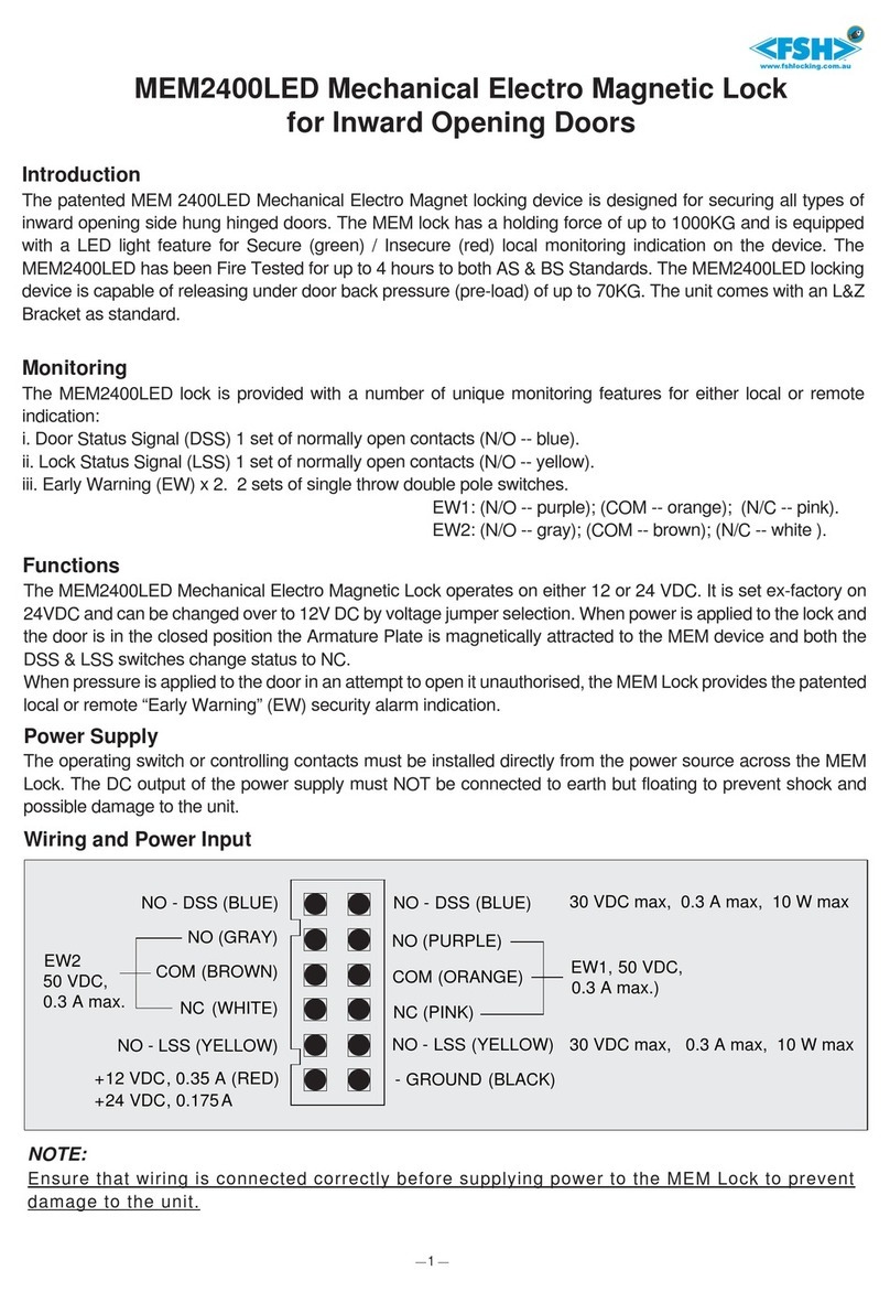
FSH
FSH MEM2400LED installation manual

Burg Wächter
Burg Wächter SecuTronic Series operating instructions

MS ENERGY
MS ENERGY MSL-20S instruction manual
rangeiot
rangeiot OrangeIOT RZ installation guide
Assa Abloy
Assa Abloy SECURITRON MORTISE UNLATCH MUNL-12 Installation and operating instructions

Ardwolf
Ardwolf A30 Quick start guides
wilson & bradley
wilson & bradley ARMSTRONG SDBCL30 instructions
