Fomotech Alpha 3000 Series User manual

1
T
TA
AB
BL
LE
E
O
OF
F
C
CO
ON
NT
TE
EN
NT
TS
S
Page
1. INTRODUCTION ....................................................................................................... 2
2. SAFETY INSTRUCTION ............................................................................................. 3
3. TRANSMITTER ILLUSTRATION
3.1 Alpha 3000F Models External Assembly ............................................................. 4
3.2 Alpha 3000F Models Internal Assembly ............................................................. 5
3.3 Alpha 3000D Models External Assembly ............................................................. 6
3.4 Alpha 3000D Models Internal Assembly ............................................................. 7
4. RECEIVER ILLUSTRATION
4.1 External Assembly (All Models) ......................................................................... 8
4.2 Alpha 3000F Models Internal Assembly ............................................................. 9
4.3 Alpha 3000D Models Internal Assembly ............................................................. 10
5. OUTPUT CONTACT DIAGRAM
5.1 Alpha 3000F2 Output Contact ............................................................................. 11
5.2 Alpha 3000F3 Output Contact ............................................................................. 12
5.3 Alpha 3000D2 Output Contact ............................................................................. 13
5.4 Alpha 3000D3 Output Contact ............................................................................. 14
6. SYSTEM CONFIGURATIONS
6.1 Jumper Settings ................................................................................................... 15~17
6.2 Security ID Code Settings ..................................................................................... 18~19
6.3 Frequency (RF) Channel Settings ....................................................................... 19~20
6.4 How to Change the Transmitter Channels.............................................................. 20~22
6.5 Frequency (RF) Channel Table ........................................................................... 23
6.6 Pushbutton Contact Settings ................................................................................. 24
6.7 Voltage Settings ..................................................................................................... 25
6.8 Steps to Change the Frequency Band ..................................................................... 26
6.9 Steps to Change the Transmitting Power................................................................. 27
7. RECEIVER INSTALLATION
7.1 Preparation for Installation ................................................................................... 28
7.2 Step-By-Step Installation ....................................................................................... 28
7.3 System Testing ....................................................................................................... 29
8. TRANSMITTER OPERATION ................................................................................... 30~31
9. TROUBLE SHOOTING ............................................................................................... 32
10. SYSTEM SPECIFICATION ......................................................................................... 33
11. PARTS LIST ................................................................................................................. 34

2
1
1.
.
I
IN
NT
TR
RO
OD
DU
UC
CT
TI
IO
ON
N
The Alpha 3000 series are highly durable, reliable, and safe industrial radio remote control system.
The versatile features of the Alpha 3000 series permit their usage in many different radio remote
control applications that required 2-step or 3-step pushbutton controls. The system can be used to
control tower cranes, factory cranes, monorail systems, multiple hoists, trolleys, mining equipment,
building construction equipment, automatic control systems, and many others.
The Alpha 3000 radio remote control systems incorporate numerous redundant safety circuits that
guaranty maximum security and ensure the system is resistant to outside interference. The major
features of the Alpha 3000 series are as follow:
* The system uses advanced 16+1bit microprocessor control with highly evolved software that has
redundant error checking and correcting capabilities to ensure 100% error-free transmission,
decoding, and control of all output relays. This highly evolved software includes CRC (cyclical
redundancy check codes) and Hamming Codes (error recovery) programming.
* To insure maximum operating safety, the Alpha 3000 system incorporates numerous important
safety features. Some of these built-in safety features include transmitter pushbutton
self-diagnosing during initial startup, transmitter low-voltage detection and warning, receiver
self-diagnosing, and MAIN deactivation when transmitter is in sleep mode, when strong RF
interference is detected, and when the transmitter is out of receiving range.
* The transmitter encoder and receiver decoder both utilize advanced microprocessor control. The
availability of 65,536 sets of unique ID codes + 63 distinct RF channels will ensure that only
commands from the matching control transmitter can be carried out without any interference
from other radio systems.
* For added safety, the system also incorporates special type of safety MAIN relay. If the safety
MAIN relay becomes defective (fails to open or close during operation), it will signal the central
system to shut down immediately to avoid the possibility of any accidents occurring.
* 63 sets of user-adjustable receiving RF channels via simple dip-switch settings.
* 100% waterproofed transmitter and receiver enclosures (IP65 rated), including the battery
compartment.
Each Alpha 3000 series radio remote control system consists of a water-resistant IP65 handheld
transmitter and receiver. The transmitter casing is molded using industrial strength composite
materials (Nylon + Fiberglass) which are impervious to dust, water, oil, acids, alkaline, heat, sunlight
and as well as being resistant to deformation due to long term use in harsh environments. The
industry’s best 2-step & 3-step pushbuttons are also constructed from industrial strength composite
materials with a minimum of up to one million press cycles. For power savings, the transmitter is
designed with an ultra high efficiency power saving circuit that requires only four “AA” size alkaline
batteries for more than 200 hours of continuos operation between battery replacements.

3
2
2.
.
S
SA
AF
FE
ET
TY
Y
I
IN
NS
ST
TR
RU
UC
CT
TI
IO
ON
N
The Alpha 3000 system is relatively simple to use, however, it is very important to observe the proper
safety procedures before, during, and after operation. When used properly our Alpha 3000 series
remote controls will enhance safety, productivity and efficiency in the workplace.
The following procedures should be strictly followed:
1. Check the transmitter casing and pushbuttons daily. Should any damage that could inhibit the
proper operation of the transmitter be found the unit should be immediately removed from
service.
2. The transmitter voltage should be checked on a daily basis. If the voltage is low (red status light
blinking - refer to page 28), the four “AA” alkaline batteries should be replaced.
3. The red emergency stop button (EMS) should be checked at the beginning of each shift to ensure
it is in proper working order and the Stop command is being received.
4. In the event of an emergency, push down the emergency stop button (EMS) immediately to
deactivate the transmitter power and the receiver MAIN relay. Then turned the power “off” from
the main power source to the crane or equipment.
5. The transmitter power key should be pulled “off” after each use and should never leave the
transmitter in the power “on” position when the unit is unattended.
6. Do not use the same RF channel and ID code as any other system in use at the same facility or
within distance of 30 meters.
7. Ensure the shoulder strap is worn at all time during operation to avoid accidental damage to the
transmitter.
8. Never operate a crane or equipment with two transmitter units at the same time with the same RF
channel and ID code.
Caution!
Improper Storage of your Spare Transmitter is a Safety Hazard! During the initial installation
of your remote control system the spare (second) transmitter should be tested to confirm that it
is functioning properly and then the batteries must be removed and the transmitter stored in a
secured place. Failure to follow this safety procedure can result in the inadvertent operation of
your crane or hoist by unauthorized personnel resulting in serious injury or death!

4
3
3.
.
T
TR
RA
AN
NS
SM
MI
IT
TT
TE
ER
R
I
IL
LL
LU
US
ST
TR
RA
AT
TI
IO
ON
N
3
3.
.1
1
A
Al
lp
ph
ha
a
3
30
00
00
0F
F
M
Mo
od
de
el
ls
s
E
Ex
xt
te
er
rn
na
al
l
A
As
ss
se
em
mb
bl
ly
y
START
1
2
4
5
6
7
8
9
10
11
12
13
14
15
16
17
3
AUX
(Transmitter Front View) (Transmitter Back View)
1. Transmitter Unit 9. Pushbutton #1 (U or ↑)
2. Status LED Display* 10. Pushbutton #3 (E or →)
3. Spare Power Key 11. Pushbutton #5 (N or ↗)
4. Pushbutton #2 (D or ↓) 12. Pushbutton #7 (START/AUX)
5. Pushbutton #4 (W or ←) 13. Warning Label
6. Pushbutton #6 (S or ↙) 14. Shoulder Strap Ring
7. Emergency Stop Button (EMS) 15. System Information
8. Power Key Switch 16. Battery Cover
17. FCC/IC Label
* Please refer to page 25 for transmitter Status LED display information
5
3
3.
.2
2
A
Al
lp
ph
ha
a
3
30
00
00
0F
F
M
Mo
od
de
el
ls
s
I
In
nt
te
er
rn
na
al
l
A
As
ss
se
em
mb
bl
ly
y
6
7
11
1
4
3
2
9
12345678
8
5
10
1 2 3 4 5678
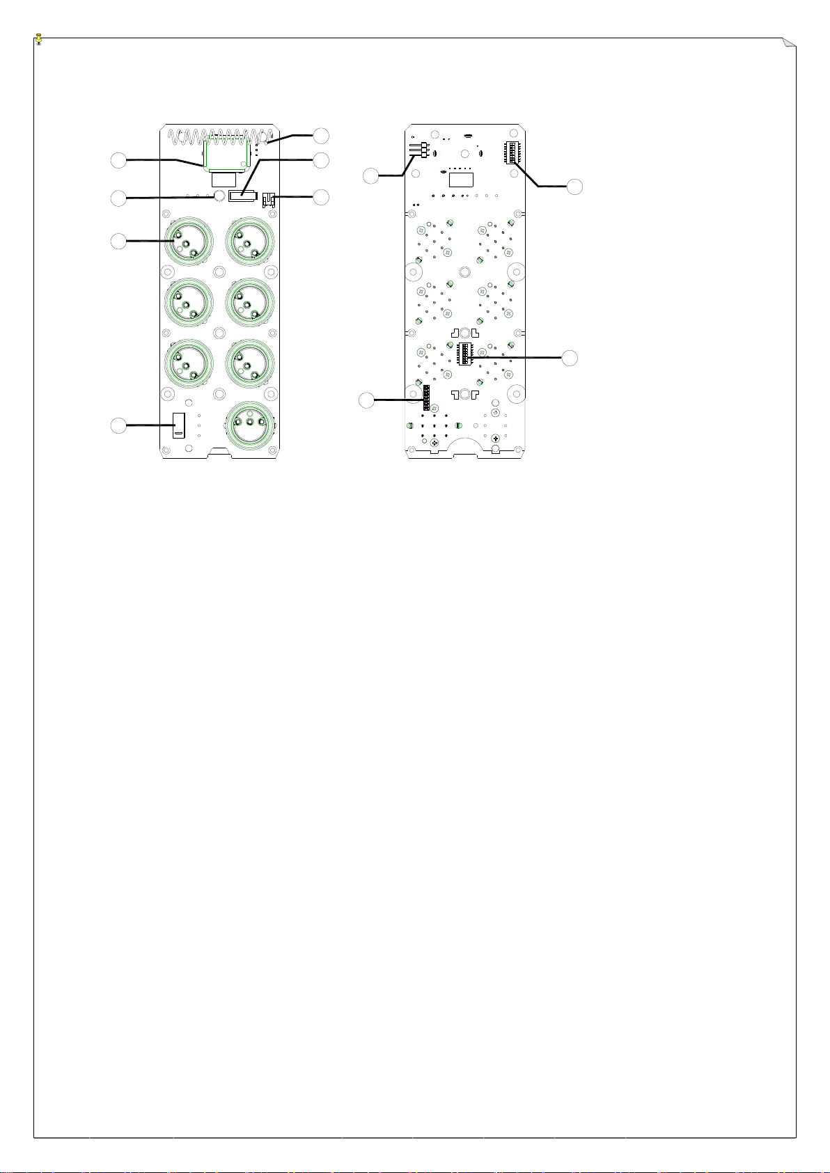
(PCB Front View) (PCB Back View)
1. RF module 6. Power ON/OFF Micro-Switch
2. Status LED Display 7. Battery Power Connector
3. 1, 2 or 3-Step Pushbuttons 8. RF test pin
4. Emergency Stop Button (EMS) 9. ID Code Soldering Slot (1st ~ 8th digit)
5. Internal Antenna 10. Channel Dip-switch
11. ID Code Dip-switch (9th~16th digit)
6
3
3.
.3
3
A
Al
lp
ph
ha
a
3
30
00
00
0D
D
M
Mo
od
de
el
ls
s
E
Ex
xt
te
er
rn
na
al
l
A
As
ss
se
em
mb
bl
ly
y
1
U
2
3
411
12
5
613
714
815
916
17
D
WE
N
S
18
10
19
20
21
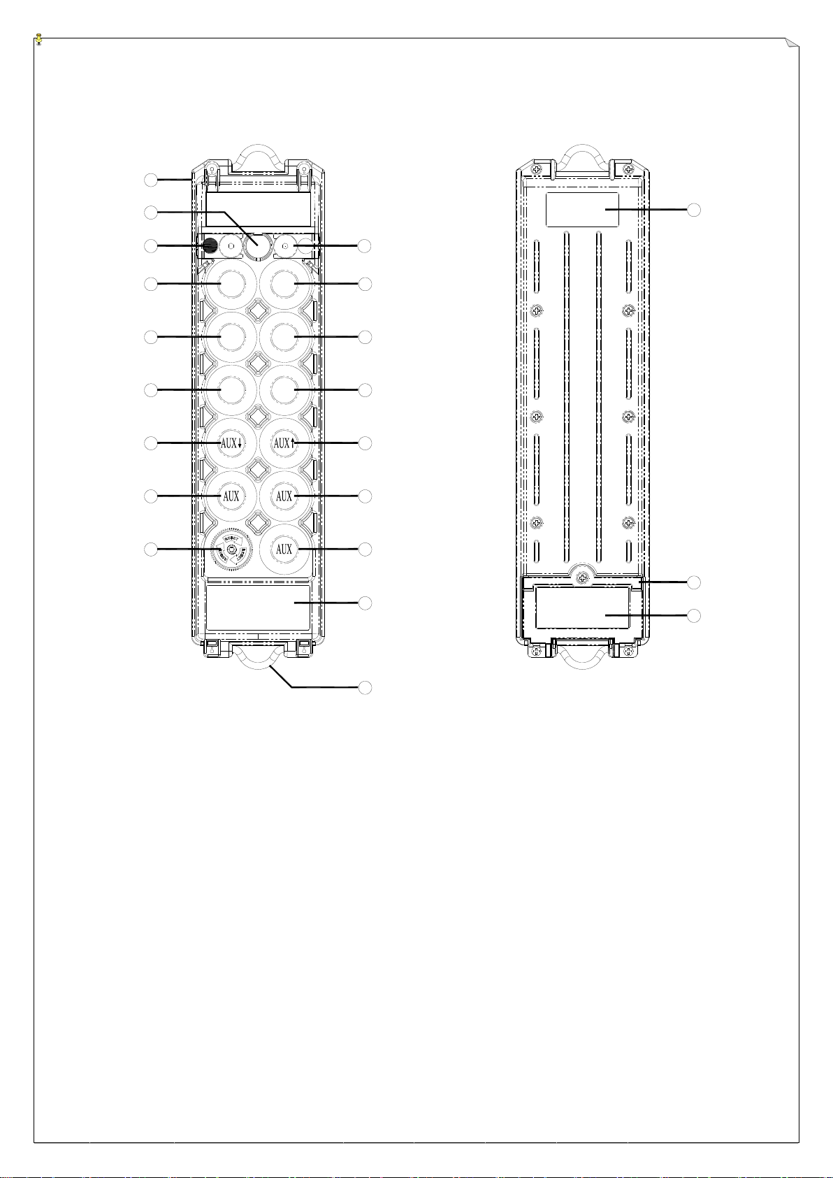
(Transmitter Front View) (Transmitter Back View)
1. Transmitter Unit 11. Pushbutton #1 (U or ↑)
2. Status LED Display* 12. Pushbutton #3 (E or →)
3. Spare Power Key 13. Pushbutton #5 (N or ↗)
4. Pushbutton #2 (D or ↓) 14. Pushbutton #7 (AUX or AUX ↑)
5. Pushbutton #4 (W or ←) 15. Pushbutton #9 (AUX or AUX →)
6. Pushbutton #6 (S or ↙) 16. Pushbutton #11 (START/AUX)
7. Pushbutton #8 (AUX or AUX ↓) 17. Warning Label
8. Pushbutton #10 (AUX or AUX ←) 18. Shoulder Strap Ring
9. Emergency Stop Button (EMS) 19. System Information
10. Power Key Switch 20. Battery Cover
21. FCC/IC Label
* Please refer to page 25 for transmitter Status LED display information
7
3
3.
.4
4
A
Al
lp
ph
ha
a
3
30
00
00
0D
D
M
Mo
od
de
el
ls
s
I
In
nt
te
er
rn
na
al
l
A
As
ss
se
em
mb
bl
ly
y
1
3
2
4
7
6
5
11
10
8765
4
3
2
1
8
9
8
7
6
5
4321
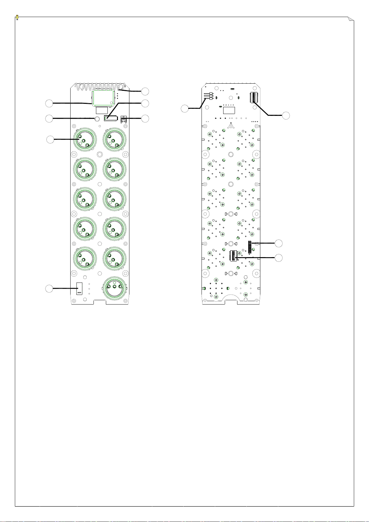
(PCB Front View) (PCB Back View)
1. RF module 6. Power ON/OFF Micro-Switch
2. Status LED Display 7. Battery Power Connector
3. 1, 2 or 3-Step Pushbuttons 8. RF test pin
4. Emergency Stop Button (EMS) 9. Channel Dip-switch Slot (1st ~ 8th digit)
5. Internal Antenna 10. ID Code Soldering
11. ID Code Dip-switch (9th~16th digit)

8
5
6
2
3
1
4
7
4
4.
.
R
RE
EC
CE
EI
IV
VE
ER
R
I
IL
LL
LU
US
ST
TR
RA
AT
TI
IO
ON
N
4
4.
.1
1
E
Ex
xt
te
er
rn
na
al
l
A
As
ss
se
em
mb
bl
ly
y
(
(A
Al
ll
l
M
Mo
od
de
el
ls
s)
)
(Alpha 3000 Models Receiver External View)
1. Antenna Seat 4. External Grounding Hole
2. Receiver Enclosure 5. Rubber ShockAbsorber
3. Key Lock 6. System Information
7. Cable Gland/Cord Grip

9
4
4.
.2
2
A
Al
lp
ph
ha
a
3
30
00
00
0F
F
M
Mo
od
de
el
ls
s
I
In
nt
te
er
rn
na
al
l
A
As
ss
se
em
mb
bl
ly
y
11
~
7
12
13
14
15
16
6
5
4
K1 K2 K3 K4 K5 K6 K7 K8 K9 K10 K11 K12
K24
K23
K22K21
~
1
2
3
8
9
10
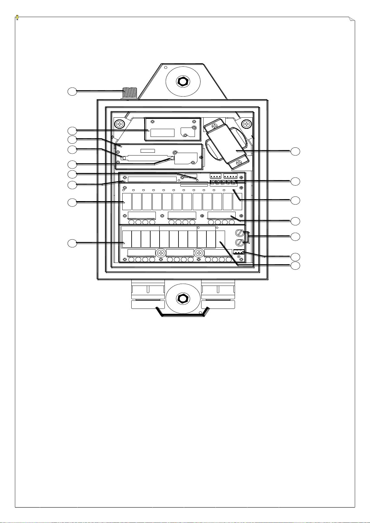
(Alpha 3000F2 & F3 Models Receiver Internal View)
1. Antenna Seat 9. Bottom Relay Board
2. Receiving RF Module 10. Power Transformer
3. Decoder Module 11. Input Voltage Selector Seat
4. Decoder Module Power Display 12. Contact Relay LED Display
5. Receiver Status LED Display* 13. Terminal Block
6. SQ Status LED Display* 14. Power Fuses (1.0A)
7. Power (AC) LED Display 15. AC Power Input
8. Upper Relay Board 16. MAIN Contact Relay
* Please refer to page 27 for Receiver and SQ display information
10
4
4.
.3
3
A
Al
lp
ph
ha
a
3
30
00
00
0D
D
M
Mo
od
de
el
ls
s
I
In
nt
te
er
rn
na
al
l
A
As
ss
se
em
mb
bl
ly
y
K21
~
1
2
3
8
9
10
11
K24
K10
K9K6
K5
K2
K1
~
7
12
13
14
15
16
6
5
4
K17 K18
K3 K4 K7 K8 K11 K12
K16K15 K19 K20 K22 K23
K14
K13
(Alpha 3000D2 & D3 Models Receiver Internal View)
1. Antenna Seat 9. Bottom Relay Board
2. Receiving RF Module 10. Power Transformer
3. Decoder Module 11. Input Voltage Selector Seat
4. Decoder Module Power Display 12. Contact Relay LED Display
5. Receiver Status LED Display* 13. Terminal Block
6. SQ Status LED Display* 14. Power Fuses (1.0A)
7. Power (AC) LED Display 15. AC Power Input
8. Upper Relay Board 16. MAIN Contact Relay
* Please refer to page 27 for Receiver and SQ display information

11
5.
OUTPUT CONTACT DIAGRAM
5
5.
.1
1
A
Al
lp
ph
ha
a
3
30
00
00
0F
F2
2
O
Ou
ut
tp
pu
ut
t
C
Co
on
nt
ta
ac
ct
t
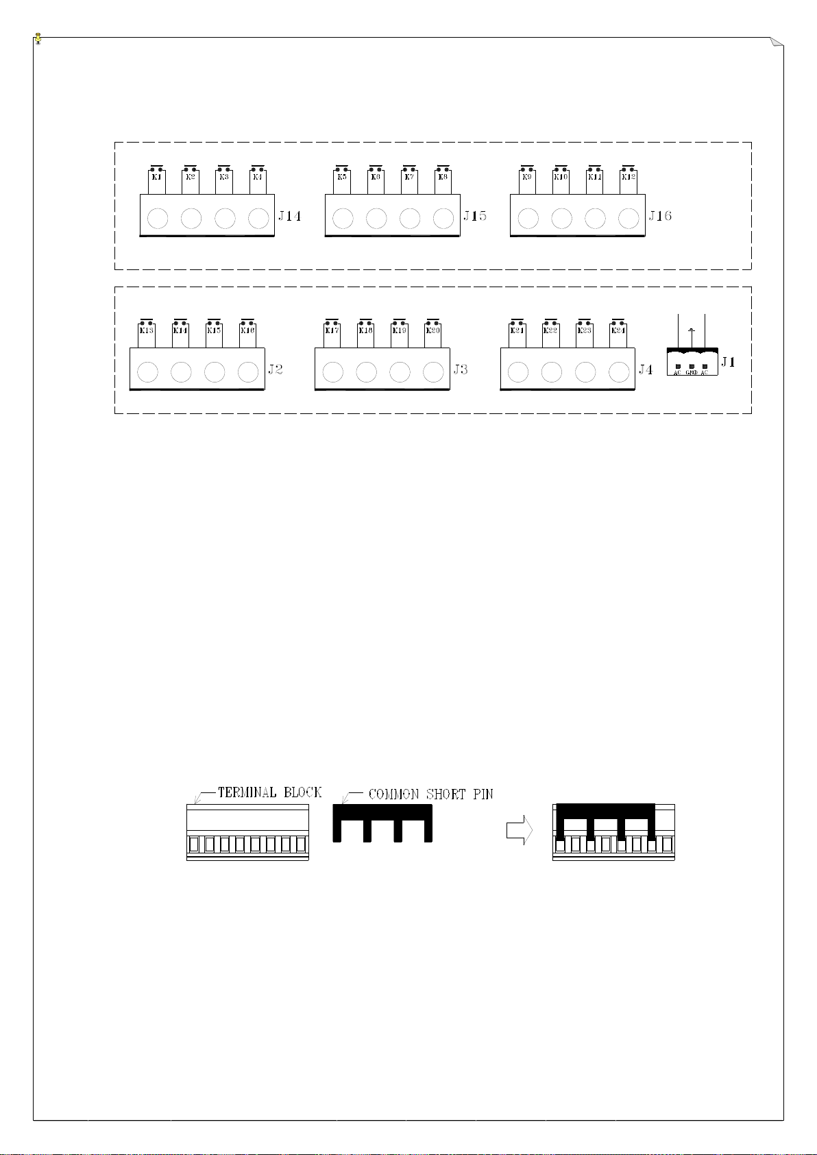
UPPER RELAY BOARD
BOTTOM RELAY BOARD
U1 U2 E1 E2 N1 N2D2
D1 W1 W2 S1 S2
ID
MAIN
AUX
Note A: AUX output contact represents the 7th pushbutton on the transmitter (START/AUX), which
can be used for lights, horn, or other types of applications (refer to section 6.6 on page 24).
Note B: The preprinted output contact markings on the relay boards below the terminal blocks are
intended forAlpha 3000F3 andAlpha 3000D3 models. If your system is an Alpha 3000F2
or an Alpha 3000D2 model, please ignore the preprinted markings and connect the wires
according to the diagram above.
Terminal Block and Common Shorting Pin Assembly
Common shorting pin illustrated above can be used rather than “daisy chaining” wiring for the
common.

12
5
5.
.2
2
A
Al
lp
ph
ha
a
3
30
00
00
0F
F3
3
O
Ou
ut
tp
pu
ut
t
C
Co
on
nt
ta
ac
ct
t
U1 D1 U2
+
D2
U3
+
D3 E1 W1 E2
+
W2
E3
+
W3 N1 S1 N2
S2
N3
S3
MAIN
UPPER RELAY BOARD
BOTTOM RELAY BOARD
+
+
AUX
Note: AUX output contact represents the 7th pushbutton on the transmitter (START/AUX), which
can be used for lights, horn, or other types of applications (refer to section 6.6 on page 24).
Terminal Block and Common Shorting Pin Assembly
Common shorting pin illustrated above can be used rather than “daisy chaining” wiring for the
common.
13
5
5.
.3
3
A
Al
lp
ph
ha
a
3
30
00
00
0D
D2
2
O
Ou
ut
tp
pu
ut
t
C
Co
on
nt
ta
ac
ct
t
U1 U2 E1 E2 N1 N2
AU1 AU2 X1 X2 Z1 ID
MAIN
UPPER RELAY BOARD
BOTTOM RELAY BOARD
D2
D1 W1 W2 S1 S2
AD1 AD2 Y1 Y2
Note A: AU & AD output contacts represent the 7th and 8th pushbuttons on the transmitter (AUX↑
& AUX↓), which can be used for the auxiliary hoist motion or other types of applications
(refer to section 6.6 on page 24).
Note B: X & Y output contacts represent the 9th and 10th pushbuttons on the transmitter (AUX),
which can be used for the auxiliary trolley motion or other types of applications (refer to
section 6.6 on page 24). X1 represents 1-speed, X2 represents 2-speed; Y1 represents
1-speed, Y2 represents 2-speed.
Note C: Z1 output contact represents the 11th pushbutton on the transmitter (START/AUX), which
can be used for lights, horn, or other types of applications (refer to section 6.6 on page 24).
Note D: The preprinted output contact markings on the relay boards below the terminal blocks are
intended forAlpha 3000F3 andAlpha 3000D3 models. If your system is an Alpha 3000F2
or an Alpha 3000D2 model, please ignore the preprinted markings and connect the wires
according to the diagram above.
Terminal Block and Common Shorting PinAssembly
Common shorting pin illustrated above can be used rather than “daisy chaining” wiring for the
common.

14
AU1 AD1 X1
UPPER RELAY BOARD
BOTTOM RELAY BOARD
U1 D1 U2
+
D2
U3
+
D3 E1 W1 E2
+
W2
E3
+
W3 N1 S1 N2
S2
N3
S3
+
+
MAIN
AUX
AU2
+
AD2
X2
+
Y2
X3
+
Y3
Y1
AU3
+
AD3
5
5.
.4
4
A
Al
lp
ph
ha
a
3
30
00
00
0D
D3
3
O
Ou
ut
tp
pu
ut
t
C
Co
on
nt
ta
ac
ct
t
Note A: AU & AD output contacts represent the 7th and 8th pushbuttons on the transmitter (AUX↑
& AUX↓), which can be used for the auxiliary hoist motion or other types of applications
(refer to section 6.6 on page 24).
Note B: X & Y output contacts represent the 9th and 10th pushbuttons on the transmitter (AUX),
which can be used for the auxiliary trolley motion or other types of applications (refer to
section 6.6 on page 24). X1 represents 1-speed, X2 represents 2-speed, X3 represents
3-speed; Y1 represents 1-speed, Y2 represents 2-speed, Y3 represents 3-speed.
Note C: AUX output contact represents the 11th pushbutton on the transmitter (START/AUX),
which can be used for lights, horn, or other types of applications (refer to section 6.6 on
page 24).
Terminal Block and Common Shorting Pin Assembly
Common shorting pin illustrated above can be used rather than “daisy chaining” wiring for the
common.
15
JUMP
6
6.
.
S
SY
YS
ST
TE
EM
M
C
CO
ON
NF
FI
IG
GU
UR
RA
AT
TI
IO
ON
NS
S
6
6.
.1
1
J
Ju
um
mp
pe
er
r
S
Se
et
tt
ti
in
ng
gs
s
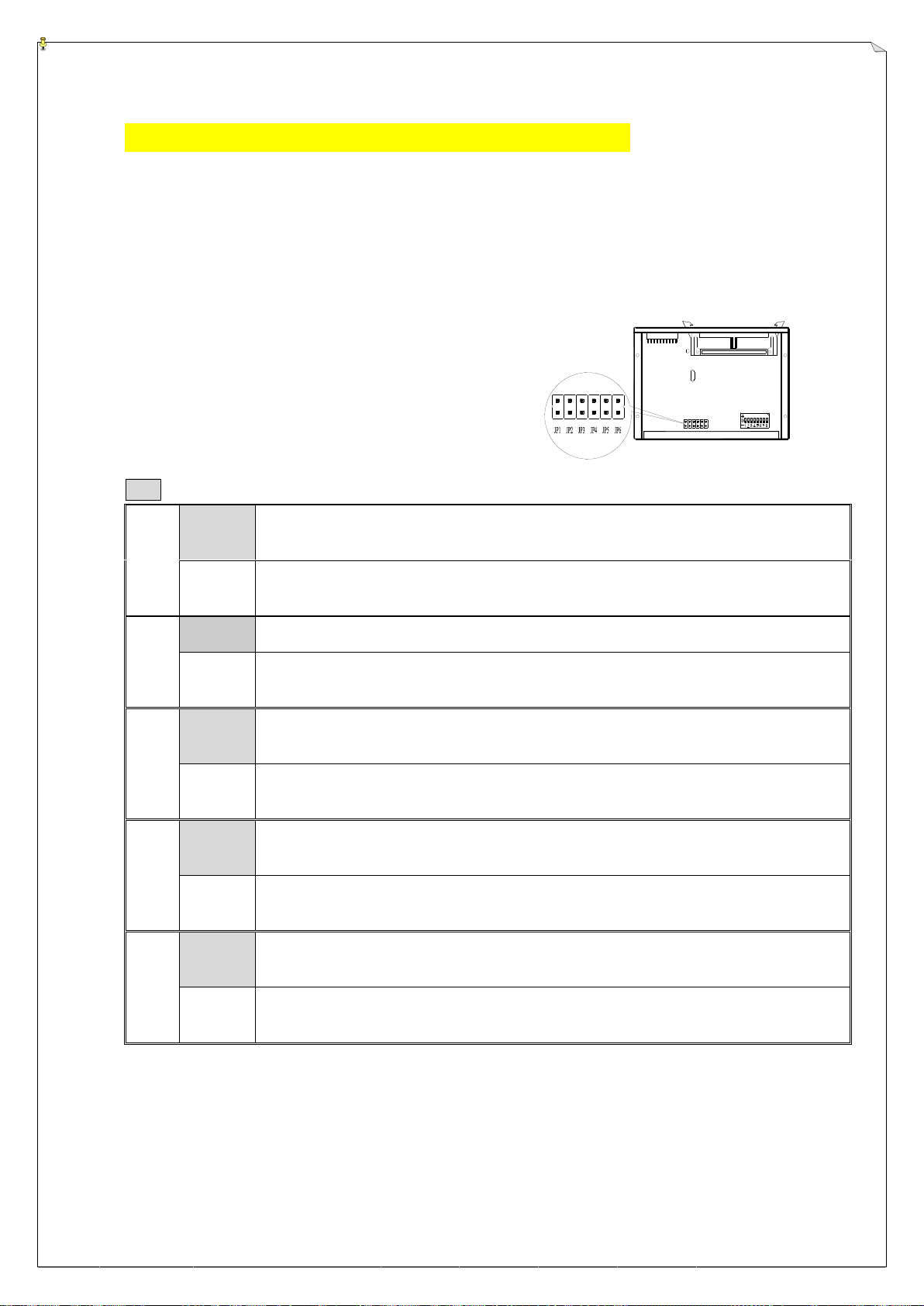
There are numerous functions that can be set via jumpers located inside the decoder module. Please
see the diagram and chart below on how to set these functions.
Manufacture Setting forAlpha 3000F2 & D2 Models
JP1
Open
* Insert the transmitter power key will activate the receiver MAIN.
* Reset the red EMS button will activate the receiver MAIN (refer to note A).
Short
* Insert the transmitter power key and press START/AUX pushbutton to activate the receiver MAIN.
* After EMS reset, press START/AUX pushbutton to activate the receiver MAIN (refer to Note A).
JP2
Open
After 5 minutes of transmitter non-usage the receiver MAIN relay will be deactivated.
Short
Receiver MAIN relay stays on constantly until the main power source to
the crane or equipment is turned off.
JP3
Open
Both 1st and 2nd speed contact relays energized (closed) when either #1 or #2 transmitter
pushbutton (U or D) is pressed to the 2nd speed.
Short
Only the 2nd speed contact relay is energized (closed) when either #1 or #2
transmitter pushbutton (U or D) is pressed to the 2nd speed.
JP4
Open
Both 1st and 2nd speed contact relays energized (closed) when either #3 or #4 transmitter
pushbutton (E or W) is pressed to the 2nd speed.
Short
Only the 2nd speed contact relay is energized (closed) when either #3 or #4
transmitter pushbutton (E or W) is pressed to the 2nd speed.
JP5
Open
Both 1st and 2nd speed contact relays energized (closed) when either #5 or #6 transmitter
pushbutton (N or S) is pressed to the 2nd speed.
Short
Only the 2nd speed contact relay is energized (closed) when either #5 or #6
transmitter pushbutton (N or S) is pressed to the 2nd speed.
Note A: If JP1 jumper is set to “Short” you must always press START/AUX pushbutton after 3 minutes of transmitter inactivity to reactivate the
receiver MAIN relay, that is 3 minutes after the last pushbutton is released. If JP1 jumper is set to “Open”, just press any command
pushbutton after 3 minutes oftransmitter inactivity to reactivate the receiver MAIN relay. If your system is equipped with Infrared Startup
Function, then JP1 jumper must set to “Short”.
Note B: Every time when you change jumper settings you must first turn the receiver power “off” and then turn it back “on” after setting so that
they can be stored in memory.

16
JUMP
Top Location →“1”
Bottom Location →“0”
Manufacture Setting forAlpha 3000D2 Model
DIP-8
“0”
Both 1st and 2nd speed contact relays energized (closed) when either #7or #8 transmitter
pushbutton (AUX ↑or AUX ↓) is pressed to the 2nd speed.
“1”
Only the 2nd speed contact relay is energized (closed) when either #7 or #8
transmitter pushbutton (AUX ↑or AUX ↓) is pressed to the 2nd speed.
Note: Every time when you change dip-switch settings please make sure to turn the receiver power “off” and then back “on” again so
that the newly selected functions can be stored in memory.
Manufacture Setting forAlpha 3000F3 & D3 Models
JP1
Open
* Insert the transmitter power key will activate the receiver MAIN.
* Reset the red EMS button will activate the receiver MAIN (refer to note A).
Short
* Insert the transmitter power key and press START/AUX pushbutton to activate the receiver MAIN.
* After EMS reset, press START/AUX pushbutton to activate the receiver MAIN (refer to Note A).
JP2
Open
After 5 minutes of transmitter non-usage the receiver MAIN relay will be deactivated.
Short
Receiver MAIN relay stays on constantly until the main power source to
the crane or equipment is turned off.
JP3
Open
Pushbutton #1 through #6 interlocked (U/D, E/W, N/S).
Short
Pushbutton #1 through #6 non-interlocked with single-speed relay contact.
JP4
Open
No acceleration delay from 1st through 3rd speed
Short
Acceleration delay for up to 1 second from 1st through 3rd speed
Note A: If JP1 jumper is set to “Short” you must always press START/AUX pushbutton after 3 minutes of transmitter inactivity to reactivate the
receiver MAIN relay, that is 3 minutes after the last pushbutton is released. If JP1 jumper is set to “Open”, just press any command
pushbutton after 3 minutes oftransmitter inactivity to reactivate the receiver MAIN relay. If your system is equipped with Infrared Startup
Function, then JP1 jumper must set to “Short”.
Note B: Every time when you change jumper settings you must first turn the receiver power “off” and then turn it back “on” after setting so that
they can be stored in memory.

17
JP1 (For all models)
JP1
Open
Insert the transmitter
power key
Press and hold
START/AUX
Receiver MAIN
activated
OR
After EMS
reset
Press and hold
START/AUX
Receiver MAIN
activated
JP1
Short
Insert the transmitter
power key
Receiver MAIN
activated
OR
After EMS reset
Re-insert the transmitter
power key
Receiver MAIN activated
* POS (power off stop): JP1 Short
JP2 (For all models)
JP2
Open
5 minutes of transmitter non-usage
Receiver MAIN deactivated
Press any pushbuttons
Receiver MAIN reactivated
JP2
Short
Receiver MAIN stays “on” constantly until the main power source to the system is turn “off”
JP3 (ForAlpha 3000F2 & 3000D2 models only)
JP3
Open
Press #1 or #2 (U or D) pushbutton
down to the 1st speed
1st speed contact relay
engaged (closed)
Press #1 or #2 (U or D) pushbutton
down to the 2stspeed
Both 1st and 2nd speed contact relays
engaged (closed)
JP3
Short
Press #1 or #2 (U or D) pushbutton
down to the 1st speed
1st speed contact relay
engaged (closed)
Press #1 or #2 (U or D) pushbutton
down to the 2stspeed
Only the 2nd speed contact relay is
engaged (closed)
JP3 (ForAlpha 3000F3 & 3000D3 models only)
JP3
Open
Pushbutton 1 through 6 interlocked
JP3
Short
Pushbutton 1 through 6 non-interlocked with each pushbutton becomes single-speed contact
JP4 (ForAlpha 3000F2 & 3000D2 models only)
JP4
Open
Press #3 or #4 (E or W) pushbutton
down to the 1st speed
1st speed contact relay
engaged (closed)
Press #3 or #4 (E or W) pushbutton
down to the 2stspeed
Both 1st and 2nd speed contact relays
engaged (closed)
JP4
Short
Press #3 or #4 (E or W) pushbutton
down to the 1st speed
1st speed contact relay
engaged (closed)
Press #3 or #4 (E or W) pushbutton
down to the 2stspeed
Only the 2nd speed contact relay is
engaged (closed)
JP4 (ForAlpha 3000F3 & 3000D3 models only)
JP4
Open
No acceleration delay from 1st through 3rd speed
JP4
Short
1st speed
depressed
After 1
second
1st speed contact
relay engaged
2nd speed
depressed
After 1
second
2nd speed contact
relay engaged
3rd speed
depressed
After 1
second
3rd speed contact relay
engaged
JP5 (ForAlpha 3000F2 & 3000D2 models only)
JP5
Open
Press #5 or #6 (N or S) pushbutton
down to the 1st speed
1st speed contact relay
engaged (closed)
Press #5 or #6 (N or S) pushbutton
down to the 2stspeed
Both 1st and 2nd speed contact relays
engaged (closed)
JP4
Short
Press #5 or #6 (N or S) pushbutton
down to the 1st speed
1st speed contact relay
engaged (closed)
Press #5 or #6 (N or S) pushbutton
down to the 2stspeed
Only the 2nd speed contact relay is
engaged (closed)
Dip-8 (ForAlpha 3000D2 model only)
DIP-8
“0”
Press #7 or #8 (AUX↑or AUX↓)
pushbutton down to the 1st speed
1st speed contact relay
engaged (closed)
Press #7 or #8 (AUX↑or AUX↓)
pushbutton down to the 2stspeed
Both 1st and 2nd speed contact relays
engaged (closed)
DIP-8
“1”
Press #7 or #8 (AUX↑or AUX↓)
pushbutton down to the 1st speed
1st speed contact relay
engaged (closed)
Press #7 or #8 (AUX↑or AUX↓)
pushbutton down to the 2stspeed
Only the 2nd speed contact relay is
engaged (closed)

18
0 1 1 0 0 11 0
Soldered ----- ' I ' Value
Not Soldered ----- ' O ' Value
6
6.
.2
2
S
Se
ec
cu
ur
ri
it
ty
y
I
ID
D
C
Co
od
de
e
S
Se
et
tt
ti
in
ng
gs
s
Transmitter ID code can be readjusted via an 8-position soldering slot (the first 8 digits of the ID code)
and an 8-position dip-switch (the last 8 digits of the ID code). Please refer to page 5 and page 7 for the
location of the soldering slot and dip-switch on the encoder board. As for the receiver ID code setting,
the soldering slot and the dip-switch are located inside the decoder module; please refer to page 9 & 10
and below illustration.
(Decoder module internal view)
Please note the first 8-digit of the ID code can be changed or altered simply by soldering the two
contact points together (“1” value); the position is at “0” value when unsoldered (two points open).
The last 8-digit ID code is set via an 8-position dip-switch located next to the 8-position soldering slot.
Due to Alpha 3000 series’ ID code (or address code) is 16-digit long, the first 8 digits are set via the
soldering slot and the remaining last 8 digits are set via the dip-switch (total of 16 digits). For the
soldering slot, the “SH8” represents the 1st digit of the ID code and “SH15” represents the 8th digit of
the ID code. As for the dip-switch, the “1” represents 9th digit of the ID code and the “8” represents the
16th digit of the ID code (last digit). Next page are some sample illustrations for better understanding
on how to set the entire 16-digit ID code via the soldering slot and the dip-switch.

19
Example 1:
ID code 00000000:10101010
Example 2:
ID code 01011001:00011100
6
6.
.3
3
F
Fr
re
eq
qu
ue
en
nc
cy
y
(
(R
RF
F)
)
C
Ch
ha
an
nn
ne
el
l
S
Se
et
tt
ti
in
ng
gs
s
All Alpha 3000 systems are also equipped with a PLL synthesized receiving RF module with
up to 63 user-adjustable RF channels. The RF channel dip-switch is located on the topside of
the receiving RF module, covered by a sliding door.
Example: For the below illustrated dip-switch
“000101”
setting, counting from
dip-position #1 to #6, the RF channel would be “205”, which also represents
frequency “301.205 MHz”. Please refer to the Frequency (RF) Channel Table or the
CHANNEL → DIP label inside the receiver door panel.
Button 2 (Channel Setup): PLLmodule power on and press button 2 to write in the channel.
LED flashes 3 times meaning the new frequency write-in is completed.
Top Slot → “1”
Bottom Slot → “0”
Procedure: 1. Open the sliding door.
2. Set the dip-switch base on the Frequency (RF) Channel Table
3. Power on the module & press button 2.
4. LED flashes 3 times to verify the frequency
5. Close sliding door and screw up.
20
6
6.
.4
4
H
Ho
ow
w
t
to
o
C
Ch
ha
an
ng
ge
e
T
Th
he
e
T
Tr
ra
an
ns
sm
mi
it
tt
te
er
r
C
Ch
ha
an
nn
ne
el
ls
s
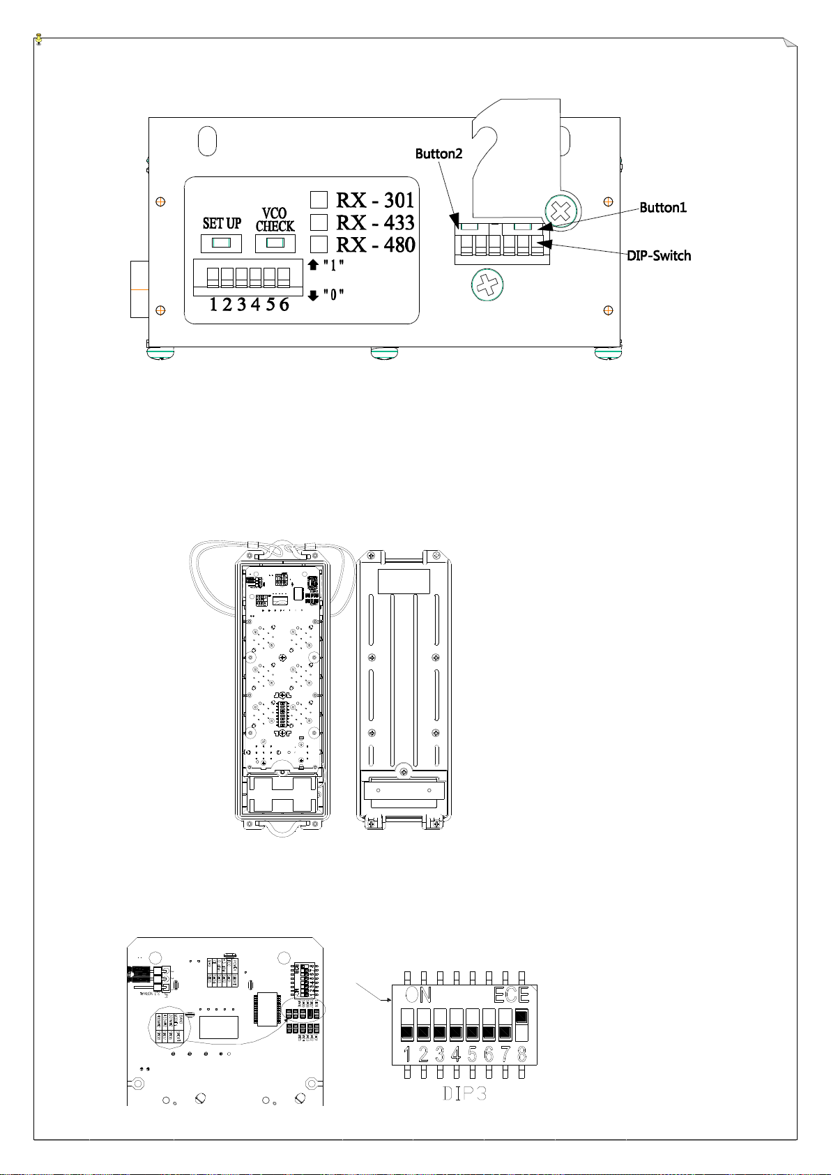
For example: Change from channel 201(301.105MHz) to 202(301.130MHz).
1. Pull out the power key.
2. Unscrew and disassemble the transmitter bottom casing then you will see the encoder board as below
Fig. 1.
(Fig.1)
3. Take out one of the batteries.
4. Find the DIP3 that is set as channel 201 (00000001) as shown on Fig.2.
This manual suits for next models
6
Table of contents
Other Fomotech Remote Control manuals

Fomotech
Fomotech Alpha 500 Series User manual

Fomotech
Fomotech Alpha 6000 User manual

Fomotech
Fomotech Alpha 604A Application guide

Fomotech
Fomotech Alpha 500 Series User manual

Fomotech
Fomotech Alpha 600 Series User manual

Fomotech
Fomotech FHSS Series Application guide

Fomotech
Fomotech Alpha 600XS Series Application guide


