Fomotech Alpha 600 Series User manual
- 1 -
T
TA
AB
BL
LE
E
O
OF
F
C
CO
ON
NT
TE
EN
NT
TS
S
Page
1. SAFETY INSTRUCTION ............................................................................................. 2
2. PUSHBUTTON CONFIGURATION
2.1 Alpha 604 Models ..................................................................................... 3
2.2 Alpha 607 & 608 Models ..................................................................................... 4
2.3 Alpha 612 Models ............................................................................................... 5
3. TRANSMITTER OUTLINE
3.1.1 Alpha 604 Models ..................................................................................... 6-7
3.1.2 Alpha 607 & 608 Models ..................................................................................... 7-8
3.1.3 Alpha 612 Models ............................................................................................. 8-10
3.2 Alpha 604/607/608/612 Spare Parts ...................................................................... 10
3.3 Charger Assembly ................................................................................................. 11
4. RECEIVER OUTLINE
4.1. Alpha 604 Models External/Internal Assembly .................................................... 12-13
4.2 Alpha 607 & 608 Models Internal Assembly ....................................................... 14-15
4.3 Alpha 612 Models Internal Assembly ................................................................... 16-17
5. OUTPUT CONTACT DIAGRAMS
5.1 Alpha 604 Models ..................................................................................... 18
5.2 Alpha 607 Models ................................................................................................. 19-20
5.3 Alpha 608 Models ................................................................................................. 21
5.4 Alpha 612 Models ................................................................................................. 22-28
6. SYSTEM CONFIGURATIONS
6.1 How to Set ID Codes ............................................................................................. 29
6.2 Transmitter RF Channel Setting ............................................................................. 30
7. RECEIVER SETTING
7.1 How to Set Receiver ID Codes .............................................................................. 31
7.2 Receiver RF Channel Setting .............................................................................. 32
7.3 Receiver Function Setting .............................................................................. 32-35
7.4 Frequency (RF) Channels Table .............................................................................. 36
8. TRANSMITTER OPERATION & STATUS LIGHT
8.1 Transmitter Operating Steps .............................................................................. 37-38
8.2 Transmitter Status light .............................................................................. 38
9. RECEIVER INSTALLATION
9.1 Preparation For Installation ................................................................................... 39
9.2 Step-By-Step Installation ....................................................................................... 39-40
9.3 System Testing ....................................................................................................... 40
9.4 Receiver System Status LED Display..................................................................... 41-42
10. BATTERY CHARGER
10.1 Charger Operation ................................................................................................. 43
10.2 Battery Charger LED Status Light ......................................................................... 44
11. TROUBLE SHOOTING................................................................................................. 45
12. SYSTEM SPECIFICATION ........................................................................................ 46-47
13. PARTS LIST ................................................................................................................. 48

2
1.
S
SA
AF
FE
ET
TY
Y
I
IN
NS
ST
TR
RU
UC
CT
TI
IO
ON
N
The Alpha 600 series are relatively simple to use, however, it is very important to observe the proper
safety procedures before, during, and after operation. When used properly, the Alpha 600 series will
enhance safety, productivity and efficiency in the workplace.
The following procedures should be strictly followed:
1. The transmitter is equipped with a specialized battery charger. Only two ”AA” Ni-MH rechargeable
batteries are allowed to be used in the transmitter. Please note the polarity of the batteries. Do not
use other types of battery to prevent any accident
2. Be sure that the battery charger is not placed in the raining, high temperature, humid and with
corroded air environment. Indoor with good ventilation is suggested.
3. Do not change the IDs on transmitter encoder and receiver decoder boards at will.
4. Check the transmitter casing and pushbuttons daily. Should any damage that could inhibit the
proper operation of the transmitter be found the unit should be immediately removed from service.
5. Check the transmitter voltage whenever it is operated. Place the transmitter into battery charger
when battery is running out or the voltage is low.
6. The red emergency stop button (EMS) should be checked at the beginning of each shift to ensure it is
in proper working order and the “Stop” command is being received by the receiver.
7. In the event of an emergency press down the EMS button will immediately deactivates the receiver
MAIN relay and the transmitter power. Then turned the power “off ” from the main power source to
the crane or equipment.
8. Do not use the same RF channel and ID code as any other system in use at the same facility or within
300-meter distance.
9. Ensure the waist belt is worn at all time during operation to avoid accidental damage to the
transmitter.
10. Rotate the power switch to OFF position when the transmitter is not operated temporarily or the
operation is finished.
11. Any repair or adjustment should be proceeding by repair technician for radio remote controls.
12. The operator should not change any electrical parts at will.

- 3 -
2.
P
PU
US
SH
HB
BU
UT
TT
TO
ON
N
C
CO
ON
NF
FI
IG
GU
UR
RA
AT
TI
IO
ON
N
2.1 Alpha 604 Models
1. α604A -- (4) single speed pushbuttons
2. α604B -- (4) double speed pushbuttons
STOPPOWER
a604
E
U
D
Below are some of many types of pushbutton configurations that are also available, please contact your dealer
for more details.
Interlocked (Can also be set to non-interlocked via an external programmer unit).
- 4 -
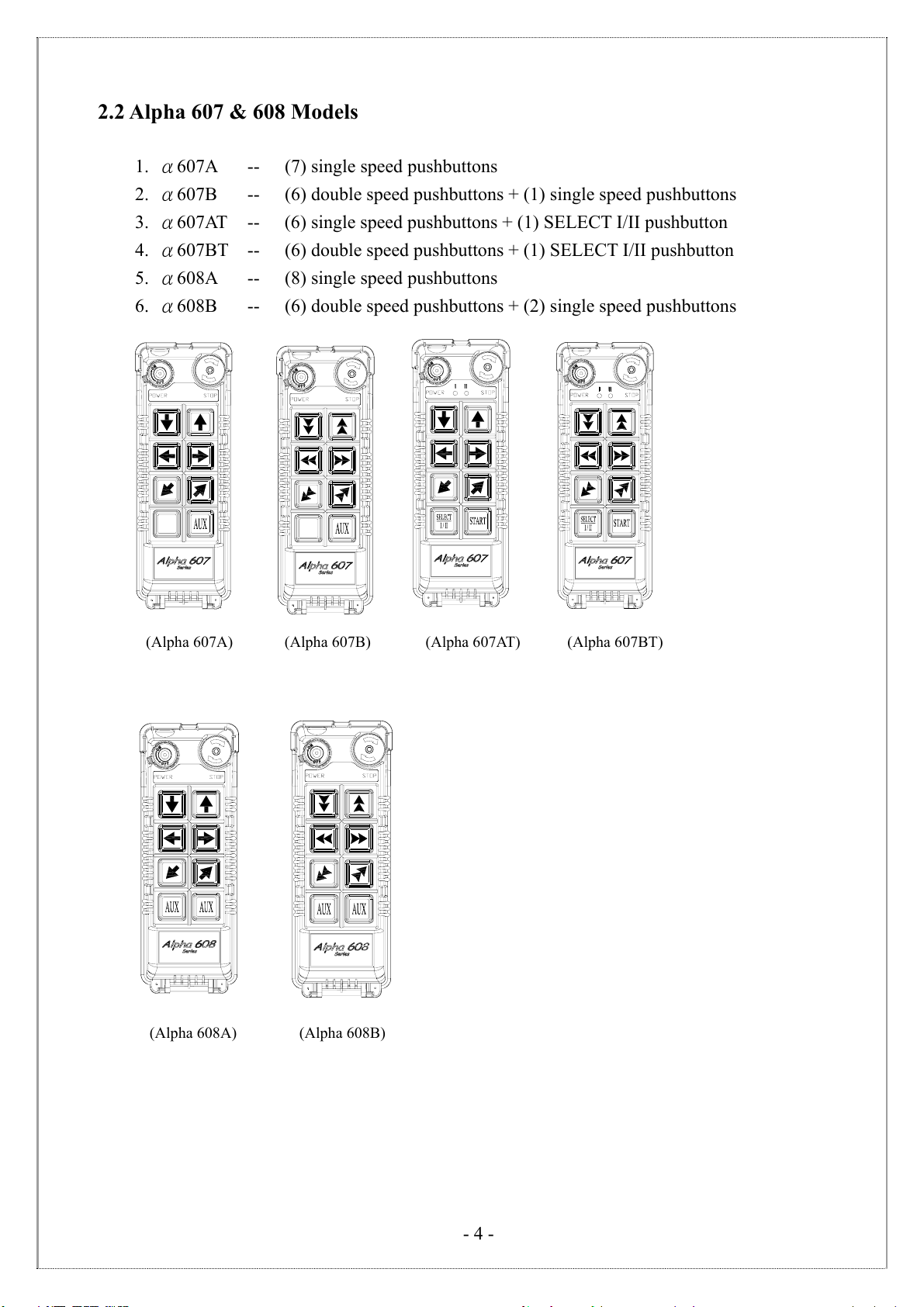
2.2 Alpha 607 & 608 Models
1. α607A -- (7) single speed pushbuttons
2. α607B -- (6) double speed pushbuttons + (1) single speed pushbuttons
3. α607AT -- (6) single speed pushbuttons + (1) SELECT I/II pushbutton
4. α607BT -- (6) double speed pushbuttons + (1) SELECT I/II pushbutton
5. α608A -- (8) single speed pushbuttons
6. α608B -- (6) double speed pushbuttons + (2) single speed pushbuttons
(Alpha 607A) (Alpha 607B) (Alpha 607AT) (Alpha 607BT)
(Alpha 608A) (Alpha 608B)
- 5 -
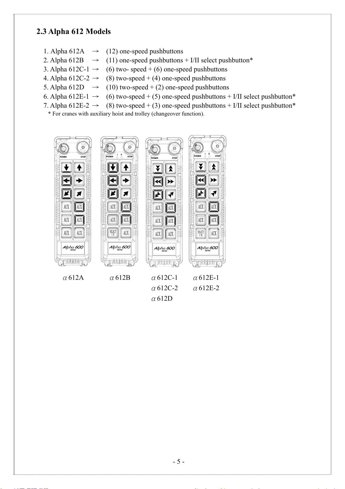
2.3 Alpha 612 Models
1. Alpha 612A →(12) one-speed pushbuttons
2. Alpha 612B →(11) one-speed pushbuttons + I/II select pushbutton*
3. Alpha 612C-1 →(6) two- speed + (6) one-speed pushbuttons
4. Alpha 612C-2 →(8) two-speed + (4) one-speed pushbuttons
5. Alpha 612D →(10) two-speed + (2) one-speed pushbuttons
6. Alpha 612E-1 →(6) two-speed + (5) one-speed pushbuttons + I/II select pushbutton*
7. Alpha 612E-2 →(8) two-speed + (3) one-speed pushbuttons + I/II select pushbutton*
* For cranes with auxiliary hoist and trolley (changeover function).
STOPPOWER STOPPOWER STOPPOWER STOPPOWER
α612C-1
α612C-2
α612D
α612E-1
α612E-2
α612A α612B

- 6 -
3
3.
.
T
TR
RA
AN
NS
SM
MI
IT
TT
TE
ER
R
O
OU
UT
TL
LI
IN
NE
E
3.1 Transmitter Outline
3.1.1 Alpha 604
3.1.1.1 SIZE:140mm X 68mm X 30mm
3.1.1.2 TX INTERNAL MODULE – Encoder board & Induction charging board
1) Encoder board 2) Induction charging board
- 7 -
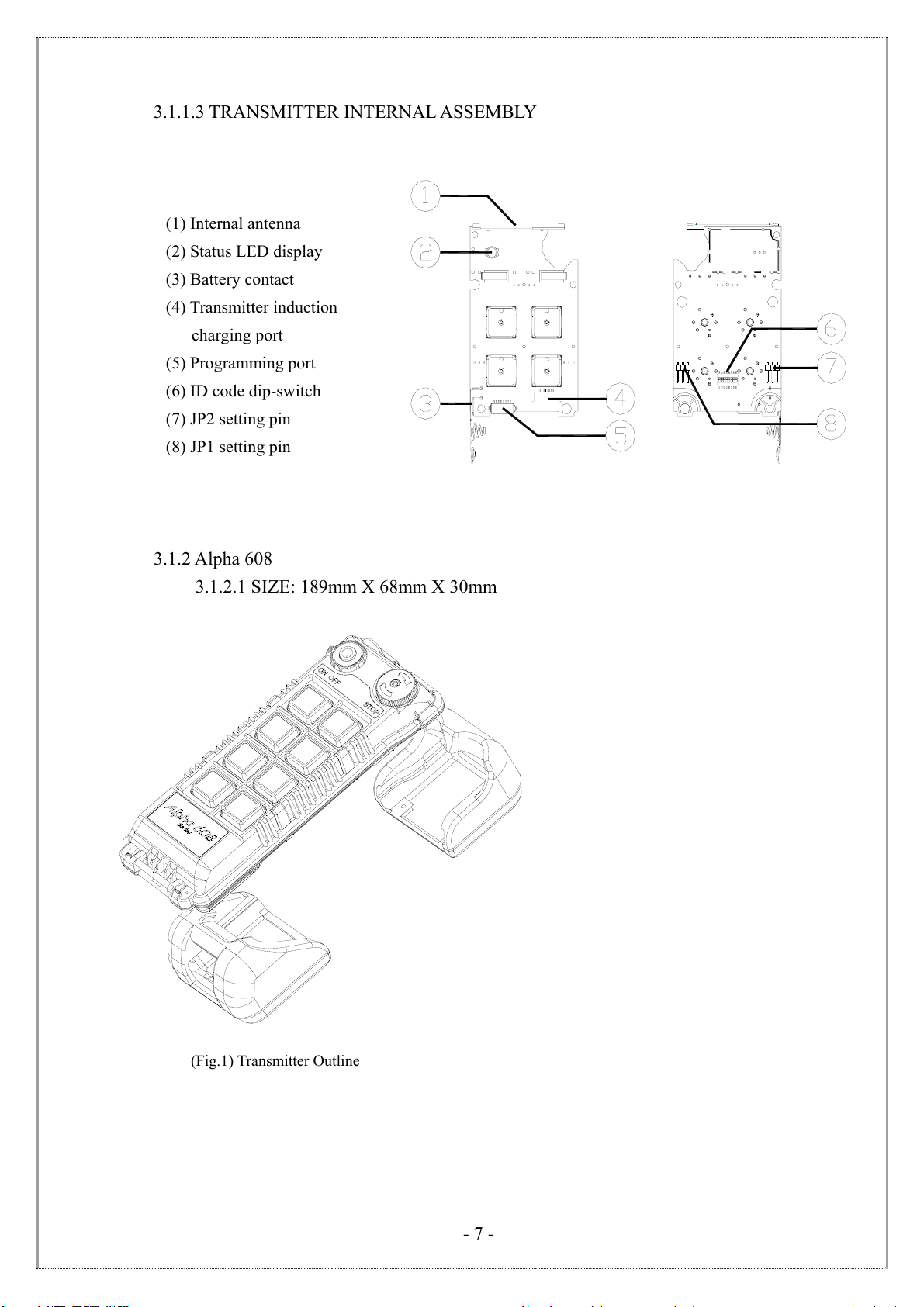
3.1.1.3 TRANSMITTER INTERNAL ASSEMBLY
(1) Internal antenna
(2) Status LED display
(3) Battery contact
(4) Transmitter induction
charging port
(5) Programming port
(6) ID code dip-switch
(7) JP2 setting pin
(8) JP1 setting pin
3.1.2 Alpha 608
3.1.2.1 SIZE: 189mm X 68mm X 30mm
(Fig.1) Transmitter Outline
- 8 -
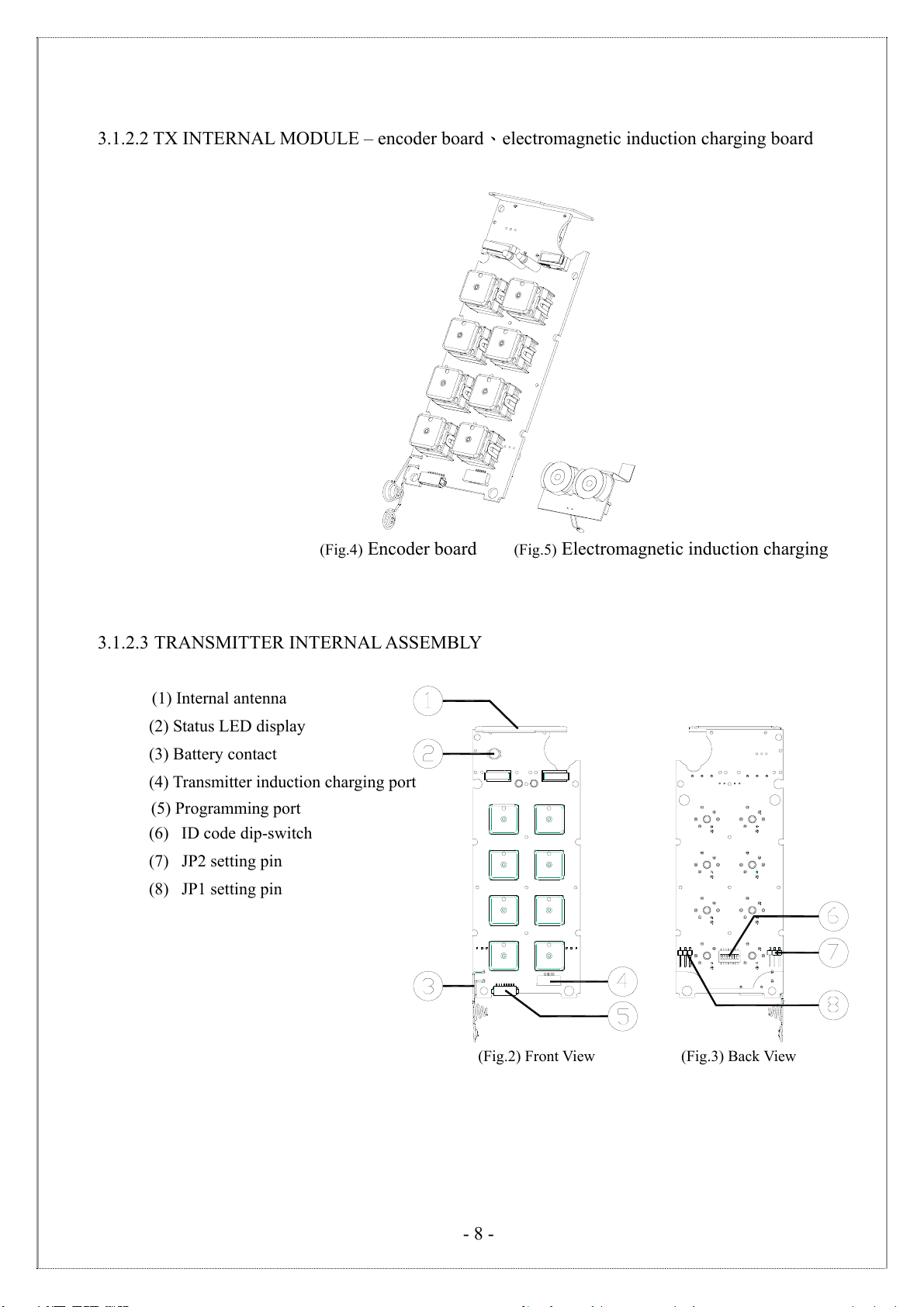
3.1.2.2 TX INTERNAL MODULE – encoder board、electromagnetic induction charging board
3.1.2.3 TRANSMITTER INTERNAL ASSEMBLY
(1) Internal antenna
(2) Status LED display
(3) Battery contact
(4) Transmitter induction charging port
(5) Programming port
(6) ID code dip-switch
(7) JP2 setting pin
(8) JP1 setting pin
(Fig.2)FrontView (Fig.3)BackView
(Fig.4) Encoder board (Fig.5) Electromagnetic induction charging
- 9 -
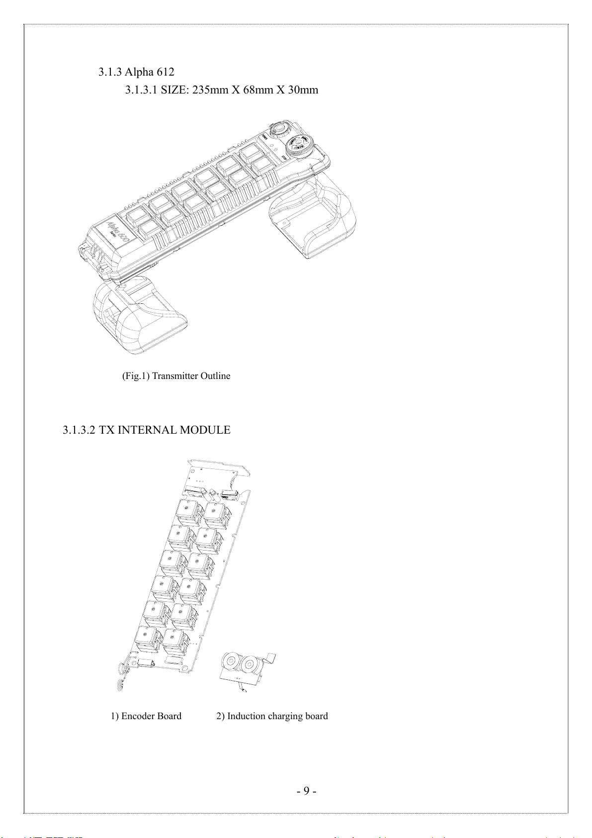
3.1.3 Alpha 612
3.1.3.1 SIZE: 235mm X 68mm X 30mm
(Fig.1) Transmitter Outline
3.1.3.2 TX INTERNAL MODULE
1) Encoder Board 2) Induction charging board

- 10 -
3.1.3.3 TRANSMITTER INTERNAL ASSEMBLY
(1) Internal antenna
(2) Status LED display
(3) Battery contact
(4) Transmitter induction charging port
(5) Programming port
(6) ID code dip-switch
(7) JP2 setting pin
(8) JP1 setting pin
(Fig.2) Front View (Fig.3) Back View
3.2 Alpha 604/607/608/612 Spare Parts
(1) Charging cable
(2) Charger
(3) Transmitter shock-absorbing rubber
(4) Shoulder strap
(5) Rechargeable batteries

- 11 -
3.3 Charge Assembly
(Fig.6) Battery Charger Assembly
Electromagnetic charging
loop board
Charging board
- 12 -
4
4.
.
R
RE
EC
CE
EI
IV
VE
ER
R
O
OU
UT
TL
LI
IN
NE
E
4
4.
.1
1
A
Al
lp
ph
ha
a
6
60
04
4
4
4.
.1
1.
.1
1
E
Ex
xt
te
er
rn
na
al
l
A
As
ss
se
em
mb
bl
ly
y
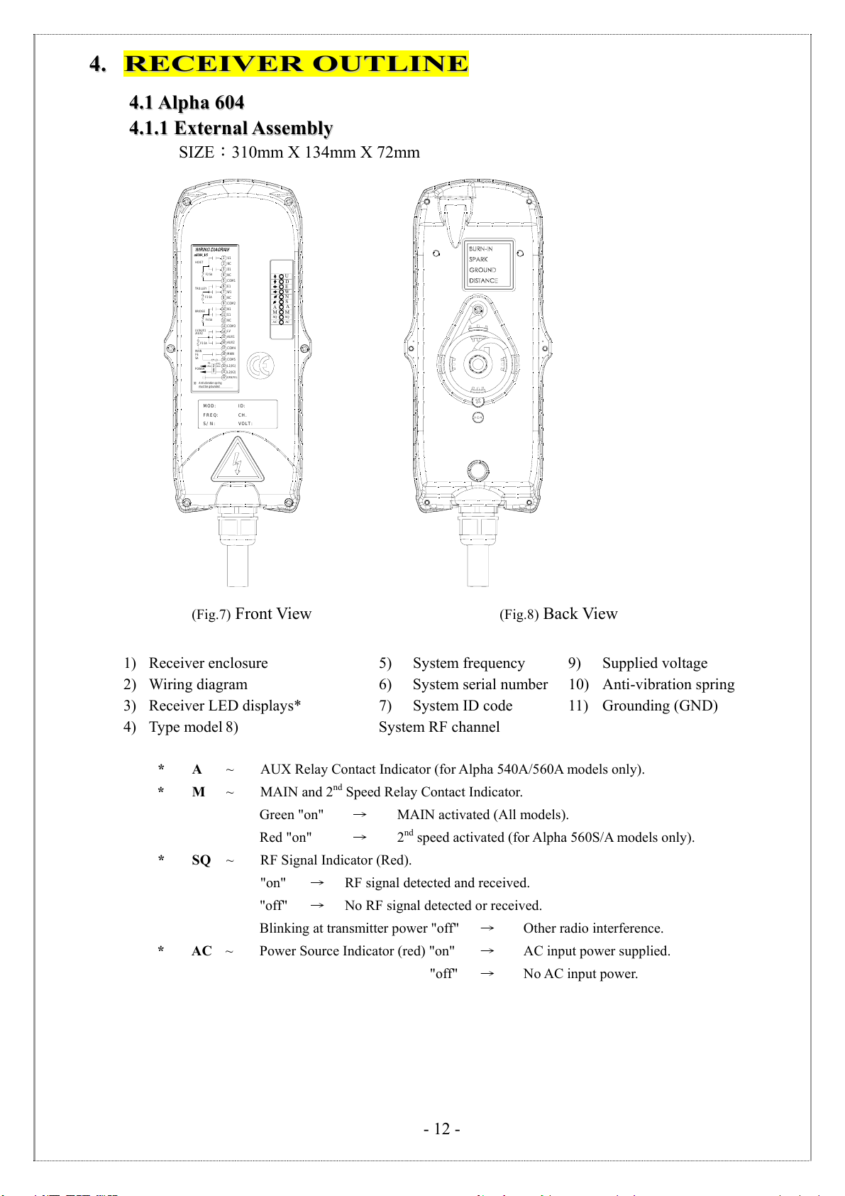
SIZE:310mm X 134mm X 72mm
AC
SQ
M
A
W
S
N
E
U
D
AC
SQ
M
A
S/ N:
FREQ:
MOD:
VOLT:
CH.
ID:
FILTER
Anti-vibration spring
must be grounded
POWER
MAIN
F6
5A
F1
F55A
LV/AUX1
COM417
L2(X2)
L1(X1)
GRN/YEL
COM5
MAIN
22
FF1
21
20
18
19
AUX1
AUX2
NC
COM3
NC
COM2
15
16
14 LV
N1
S1
COM1
D1
W1
E1
NC
NC
U1
F45A
F35A
13
10
11
12
9
8
3
5
6
7
4
F25A
2
1
BRIDGE
TROLLEY
HOIST
/AUX2
(Fig.7) Front View (Fig.8) Back View
1) Receiver enclosure 5) System frequency 9) Supplied voltage
2) Wiring diagram 6) System serial number 10) Anti-vibration spring
3) Receiver LED displays* 7) System ID code 11) Grounding (GND)
4) Type model 8) System RF channel
* A ~ AUX Relay Contact Indicator (for Alpha 540A/560A models only).
* M ~ MAIN and 2nd Speed Relay Contact Indicator.
Green "on" →MAIN activated (All models).
Red "on" →2
nd speed activated (for Alpha 560S/A models only).
* SQ ~ RF Signal Indicator (Red).
"on" →RF signal detected and received.
"off" →No RF signal detected or received.
Blinking at transmitter power "off" →Other radio interference.
* AC ~ Power Source Indicator (red) "on" →AC input power supplied.
"off" →No AC input power.

- 13 -
1
2
3
4
4
4.
.1
1.
.2
2
A
Al
lp
ph
ha
a
6
60
04
4
I
In
nt
te
er
rn
na
al
l
A
As
ss
se
em
mb
bl
ly
y
(Fig.15)InternalPartsAssembly
1) Receiving RF module
2) Secondary power AC fuse (0.50A)
3) Primary power AC fuse (1.0A)
4) System status LED display*
5) External antenna port
6) ID code dip-switch
7) RF channel dip-switch
8) Contact relay LED display
9) Pushbutton #1 and #2 fuse (5.0A)
10) MAIN fuse (5.0A)
11) Contact output seat (CN3)
12) Low-voltage (LV) fuse (5.0A)
13) Contact output seat (CN4)
14) Pushbutton #3 and #4 fuse (5.0A)
15) AC power input seat (CN2)
16) Cable gland & output cable
* Please refer to page 32 for system status
LED display information.
1) Spare fuse & jumper compartment
2) Spare Jumper slots
3) Spare fuse slots
4) Receiver top casing
3
7
6
8
9
10
11
12
14
15
5
13
16
FUSE
FUSE
FUSE
FUSE
FUSE
1
2
4
- 14 -
4
4.
.2
2
A
Al
lp
ph
ha
a
6
60
07
7/
/6
60
08
8
4
4.
.2
2.
.1
1
E
Ex
xt
te
er
rn
na
al
l
A
As
ss
se
em
mb
bl
ly
y
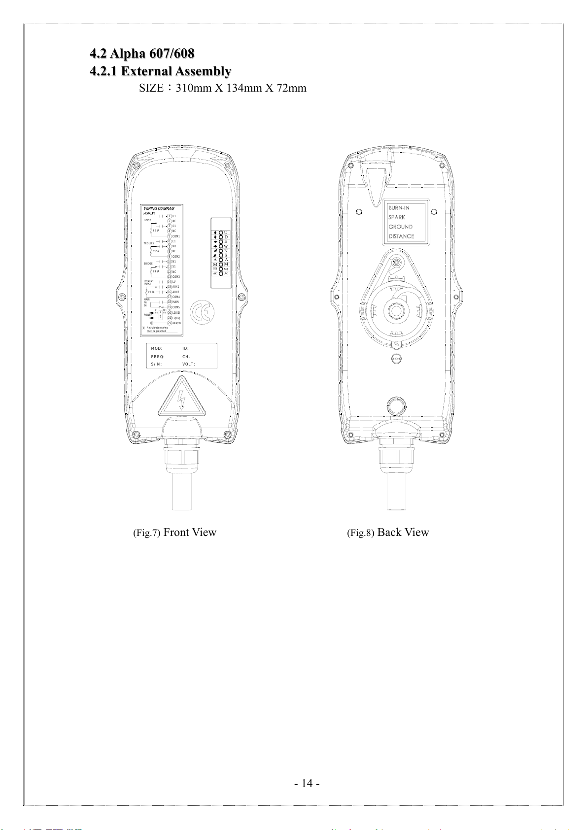
SIZE:310mm X 134mm X 72mm
AC
SQ
M
A
W
S
N
E
U
D
AC
SQ
M
A
S/ N:
FREQ:
MOD:
VOLT:
CH.
ID:
FILTER
Anti-vibration spring
must be grounded
POWER
MAIN
F6
5A
F1
F5 5A
LV/AUX1
COM417
L2(X2)
L1(X1)
GRN/YEL
COM5
MAIN
22
FF1
21
20
18
19
AUX1
AUX2
NC
COM3
NC
COM2
15
16
14 LV
N1
S1
COM1
D1
W1
E1
NC
NC
U1
F4 5A
F3 5A
13
10
11
12
9
8
3
5
6
7
4
F2 5A
2
1
BRIDGE
TROLLEY
HOIST
/AUX2
(Fig.7) Front View (Fig.8) Back View
- 15 -
4
4.
.2
2.
.2
2
A
Al
lp
ph
ha
a
6
60
08
8
I
In
nt
te
er
rn
na
al
l
A
As
ss
se
em
mb
bl
ly
y
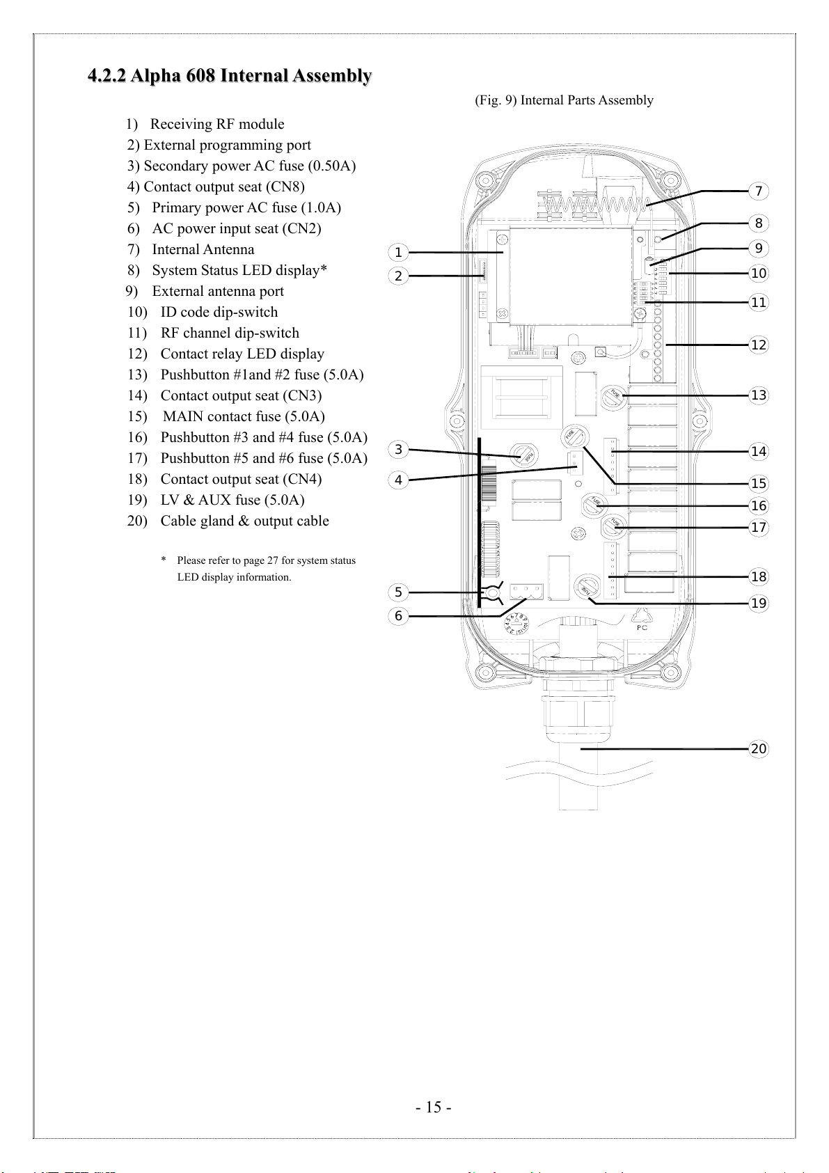
(Fig. 9) Internal Parts Assembly
1) Receiving RF module
2) External programming port
3) Secondary power AC fuse (0.50A)
4) Contact output seat (CN8)
5) Primary power AC fuse (1.0A)
6) AC power input seat (CN2)
7) Internal Antenna
8) System Status LED display*
9) External antenna port
10) ID code dip-switch
11) RF channel dip-switch
12) Contact relay LED display
13) Pushbutton #1and #2 fuse (5.0A)
14) Contact output seat (CN3)
15) MAIN contact fuse (5.0A)
16) Pushbutton #3 and #4 fuse (5.0A)
17) Pushbutton #5 and #6 fuse (5.0A)
18) Contact output seat (CN4)
19) LV & AUX fuse (5.0A)
20) Cable gland & output cable
* Please refer to page 27 for system status
LED display information.
FUSE
FUSE
FUSE
1
2
8
4
11
10
12
13
14
15
17
18
9
16
20
FUSE
FUSE
FUSE
3
5
6
7
19
- 16 -
4
4.
.3
3
A
Al
lp
ph
ha
a
6
61
12
2
4
4.
.3
3.
.1
1
E
Ex
xt
te
er
rn
na
al
l
A
As
ss
se
em
mb
bl
ly
y
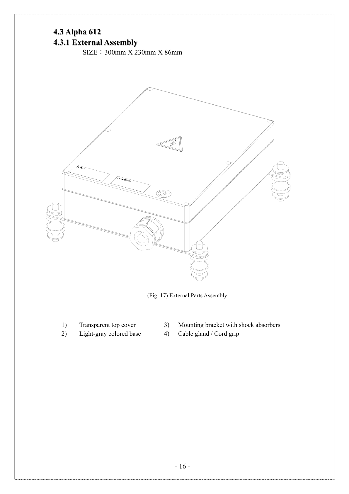
SIZE:300mm X 230mm X 86mm
(Fig. 17) External Parts Assembly
1) Transparent top cover 3) Mounting bracket with shock absorbers
2) Light-gray colored base 4) Cable gland / Cord grip

- 17 -
17
20
19
18
16
14
5
10
11
9
7
8
6
1
3
4
213
15
12
4
4.
.3
3.
.2
2
A
Al
lp
ph
ha
a
6
61
12
2
I
In
nt
te
er
rn
na
al
l
A
As
ss
se
em
mb
bl
ly
y
(Fig. 18) Internal Parts Assembly
1) Power LED display* 12) Pushbutton #1 and #2 relay fuse (5.0A)
2) SQ LED display** 13) Receiving RF module
3) Status LED display**** 14) External antenna port
4) DC power relay LED display*** 15) RF channel dip-switch
5) Programming port 16) ID code dip-switch
6) Jumper settings 17) Secondary power fuse (0.8A)
7) Function dip-switch 18) Voltage selector seat
8) Pushbutton #3 and #4 relay fuse (5.0A) 19) MAIN relay fuse (5.0A)
9) Pushbutton #5 and #6 relay fuse (5.0A) 20) Pushbutton A4 relay fuse (5.0A)
10) Pushbutton A1and A2 relay fuse (5.0A)21) Primary power fuse (1.0A)
11) Pushbutton A3 relay fuse (5.0A) 22) Low-voltage (LV) relay fuse (5.0A)
* POWER ~ AC Power Source Indicator "on" →AC input power supplied.
"off" →No AC input power.
** SQ ~ RF Signal Indicator "on" →RF signal detected and received.
"off" →No RF signal detected or received.
Blinking at transmitter power “off” →Other radio interference.
*** RELAY_COM ~ DC Power Source to Relays "on" →DC power to relays.
"off" →No DC power to relays.
**** STATUS ~ Receiver System Status LED Display →Please refer to page 32.
- 18 -
5
5.
.
O
OU
UT
TP
PU
UT
T
C
CO
ON
NT
TA
AC
CT
T
D
DI
IA
AG
GR
RA
AM
MS
S
5
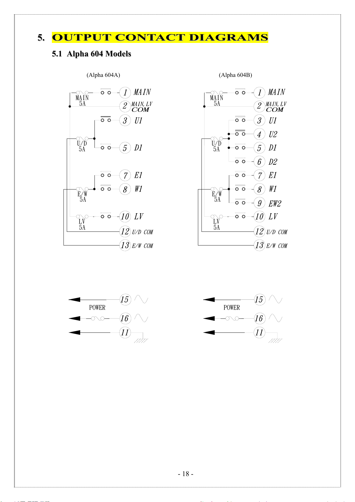
5.
.1
1
A
Al
lp
ph
ha
a
6
60
04
4
M
Mo
od
de
el
ls
s
(Alpha 604A) (Alpha 604B)
POWER
LV
5A
E/W
5A
U/D
5A
MAIN
5A
POWER
LV
5A
E/W
5A
U/D
5A
MAIN
5A
- 19 -
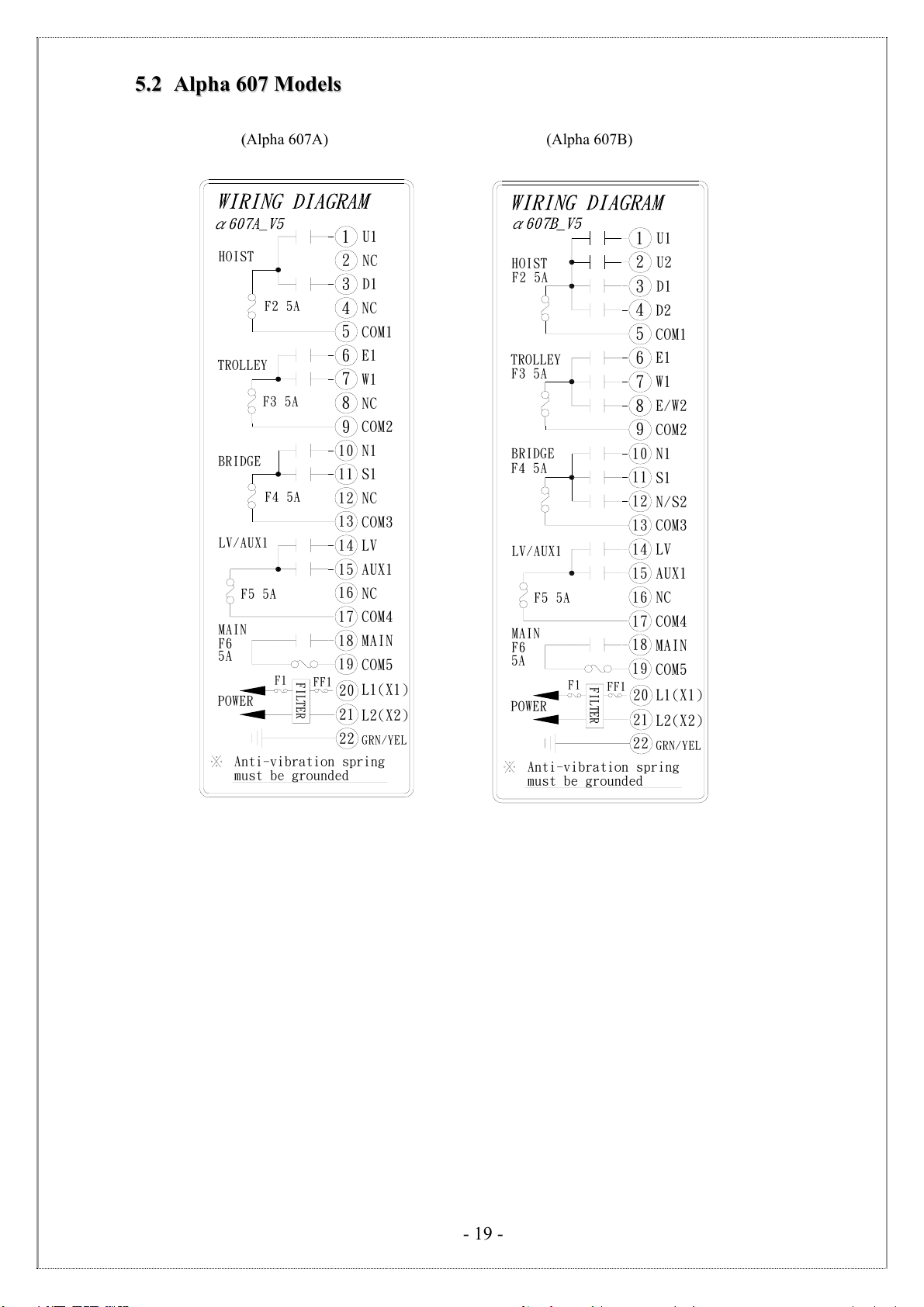
5
5.
.2
2
A
Al
lp
ph
ha
a
6
60
07
7
M
Mo
od
de
el
ls
s
(
(Alpha 607A) (Alpha 607B)
FILTER
Anti-vibration spring
must be grounded
POWER
MAIN
F6
5A
F1
F5 5A
LV/AUX1
COM4
17
L2(X2)
L1(X1)
GRN/YEL
COM5
MAIN
22
FF1
21
20
18
19
AUX1
NC
NC
COM3
NC
COM2
15
16
14 LV
N1
S1
COM1
D1
W1
E1
NC
NC
U1
F4 5A
F3 5A
13
10
11
12
9
8
3
5
6
7
4
F2 5A
2
1
BRIDGE
TROLLEY
HOIST
FILTER
Anti-vibration spring
must be grounded
POWER
MAIN
F6
5A
F1
F5 5A
LV/AUX1
BRIDGE
F4 5A
TROLLEY
F3 5A
COM4
17
L2(X2)
L1(X1)
GRN/YEL
COM5
MAIN
22
FF1
21
20
18
19
AUX1
NC
N/S2
COM3
E/W2
COM2
15
16
14
13 LV
N1
10
11
12 S1
9
8
COM1
D1
3
5
6
7W1
E1
4D2
HOIST
F2 5A 2
1U2
U1

- 20 -
FILTER
Anti-vibration spring
must be grounded
POWER
MAIN
F6
5A
F1
F5 5A
LV/SEL-I
COM4
17
L2(X2)
L1(X1)
GRN/YEL
COM5
MAIN
22
FF1
21
20
18
19
SEL-I
SEL-II
NC
COM3
NC
COM2
15
16
14 LV
N1
S1
COM1
D1
W1
E1
NC
NC
U1
F4 5A
F3 5A
13
10
11
12
9
8
3
5
6
7
4
F2 5A
2
1
BRIDGE
TROLLEY
HOIST
/SEL-II
(
(Alpha 607AT) (Alpha 607BT)
FILTER
Anti-vibration spring
must be grounded
POWER
MAIN
F6
5A
F1
F5 5A
LV/SEL-I
BRIDGE
F4 5A
TROLLEY
F3 5A
COM4
17
L2(X2)
L1(X1)
GRN/YEL
COM5
MAIN
22
FF1
21
20
18
19
SEL-I
SEL-II
N/S2
COM3
E/W2
COM2
15
16
14
13 LV
N1
10
11
12 S1
9
8
COM1
D1
3
5
6
7W1
E1
4D2
HOIST
F2 5A 2
1U2
U1
/SEL-II
This manual suits for next models
15
Table of contents
Other Fomotech Remote Control manuals

Fomotech
Fomotech Alpha 600XS Series Application guide

Fomotech
Fomotech FHSS Series Application guide

Fomotech
Fomotech Alpha 500 Series User manual

Fomotech
Fomotech Alpha 604A Application guide

Fomotech
Fomotech Alpha 3000 Series User manual

Fomotech
Fomotech Alpha 6000 User manual

Fomotech
Fomotech Alpha 500 Series User manual


