8
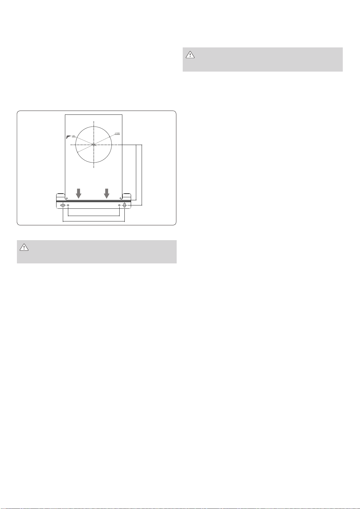
Support bracket
Having established the position of the appliance, drill no. 2 Ø 6 holes
to apply the support bracket (use the same bracket to mark the holes).
Secure it with the plugs supplied.
Below is descried the type of rear and horizontal outlet which is the
most common:
hPosition the paper template between the wall and the appliance
support ns
hMark the centre of the hole of the pipe
hDrill a Ø 105 mm hole as indicated on the paper template
hConnect the appliance to the support bracket and connect the
ue gas release tubes.
Electrical connection
Electrical current with 230V voltage
Before any work on the electrical equipment, always dis-
connect the 230V voltage.
Connect the supplied cable to the line respecting the phase, neutral
and earth.
In the event of replacement of the power supply cable, an operation
which must in any case be performed by a qualied technician, connect
the appliance with a cable type H 05 V VF 3 x 0.75 mm2 with Ø max
7mm similar to that provided. In addition, the earth wire must be
30 mm longer than the power supply cables. Power the appliance via
an all-pole switch with an opening of at least 3 mm between the con-
tacts. For maintenance operations, disconnect the power by turning
the omni-pole switch.
N.B. no responsibility is accepted for damage to persons, animals or
property caused by failure to earth the appliance and the creation of
an electrical installation that does not comply with current standards
(CEI 68.4).
Arrange for qualied personnel to check that the electrical installation
is suitable for the maximum power absorbed by the appliance, as in-
dicated on the data plate, ensuring in particular that the wire section
of the systemis suitable for the power absorbed by the appliance.
For the main power supply of the appliance from the mains, the use
of adapters, multiple sockets and/or extension cords is not permitted.
The use of any component that uses electricity involves the observance
of a number of fundamental rules such as:
hDo not touch the appliance with wet parts of the body and/
or bare feet
hDo not pull the electrical cables
hDo not leave the appliance exposed to atmospheric agents
(rain, sun, etc.)
hDo not allow the appliance to be used by children or inexpe-
rienced persons.
The power cable of the appliance must not be replaced by the user.
If the cable becomes damaged, switch off the appliance and for the purposes
of replacement, use exclusively professionally qualied personnel.
Where the appliance will not be used for a certain period of time, it is
advisable to disconnect the power supply to all the system components
that use electricity.
Gas connection
Non-compliance with theapplicable laws may result in re or
explosions, causing serious damage to materials, animals or
persons, possibly even irreparable
Determine the diameter of the pipe in accordance with the regulations
in force.
Before installing the appliance blow into the gas pipe in order to
remove any residue. Connect the water heater to the gas pipe of the
internal system and t upstream from the appliance a valve for gas
interception and opening.
Comply with the prescriptions of the relevant standard.
For initial start-up of the appliance, the following checks must be
carried out by qualied technicians:
hChecking for internal and external leakage of the gas supply
system
hAdjustment of the gas ow rate according to the power re-
quired by the appliance
hThat the appliance is powered by the type of gas for which it
was designed
hThat the gas supply pressure is in the range between the values
indicated on the data plate
hThat the gas supply system is dimensioned for the capacity
required by the appliance and is equipped with all the safety
and control devices required by current regulations.In caso di
assenza prolungata dell’utente dell’apparecchio, chiudere il ru-
binetto principale di adduzione del gas all’apparecchio.
In case of prolonged absence of the user of the appliance, close the
main gas supply valve to the appliance.
Do not obstruct the ventilation openings of the room where a gas
appliance is installed in order to avoid dangerous situations such as
the formation of toxic and explosive mixtures.
Do not use the gas pipes as electrical appliance earthing devices.
Water connection
Connect the water heater to the water mains and t a water shut-off
valve upstream from the appliance.
Looking at the appliance, the cold water inlet is on the right and the
hot water outlet is on the left.
Make sure that the piping of your water system is not being used as
an earth electrode for your electric or telephone system. It would
be completely unsuitable for this purpose.
Severe damage to the pipes could occur in a short space of time and
to the appliance.
The minimum distance between the water heater and sampling point
of hot water must exceed of 0,5 m.
Evacuation of combustion products
The manufacturer separately supplies various types of air intake and
fume exhaust pipes specic for any installation need.
By varying the type of installation the classication of the water heater
also varies, precisely:
hB type: the terminal takes air intake directly from the room in
which the water heater has been installed.
The room must be ventilated by a suitable air intake meeting
current standards.
hC type: The water heater is a type C appliance (sealed cham-
ber) and must therefore have a secure connection to the ue
release tube and combustion air intake that both ow outside
and without which the appliance cannot function.
In rooms with corrosive vapour risks (for example, laundries, hair
dressers, galvanic processing rooms, etc.), it is very important to use the
type C installation with air intake for combustion from the outdoors.
This protects the appliance against corrosion effects.
For exhaust product evacuation, refer to current regulations. The
Fig. 6 - Support bracket
177
162
150
180


