Fondital LIPARI TN 11i Installation and operating instructions

IST 03 C 1079 - 01
DOMESTIC GAS WATER HEATERS
INSTALLATION, USE AND MAINTENANCE
LIPARI TN
11i - 14i
EN
Translation of the original
instructions (in Italian)


3
The device is well built in accordance with the current legislation.
The CE sign positioned on the product indicates that it conforms to the following European Directives:
• Gas appliance directive 2009/142/EC
• Directive 2009/125/EC Ecodesign requirements for energy-related products
• Directive 2010/30/EU Indication of the consumption of energy by labelling
• Delegated regulation (EU) no. 812/2013
• Delegated regulation (EU) no. 814/2013
A
B
C
D
E
F
G
A
YZ dB
WXYZ YZ
kWh/annum GJ/annum
2015 812/2013
I II
15
2
3
4
6
7
1Name of supplier or brand
2Water heating function: load prole
3Energy efciency class
4Indoor sound power level
5Model
6Water heating energy efciency class
7Annual energy consumption
PRODUCT DATASHEET
Fondital Lipari Tn 11i Lipari Tn 14i
2Declared load prole M L
4Indoor sound power level dB(A) 56 58
6Water heating energy efciency class A A
Water heating energy efciency class % 73,8 76,9
7
Annual energy consumption GJ 6 12
Annual energy consumption kWh 0 0
Nitrogen oxide emissions mg/kWh 103 108
The appliance complies with the European Directive 2010/30/EU “ErP Energy Labelling”.
The energy label carries the information regarding the product's energy efciency characteristics.
In this way the end consumer can identify and compare similar products and can make informed choices regarding high efciency
appliances.
Below is a description of the label xed to the shell of the appliance and the product sheet with the information required by the
Directive.

4
In parts of the manual the following symbols are used:
WARNING = for actions that require caution and adequate prepara-
tion
PROHIBITED = for actions that MUST NOT be performed
The water heater package contains:
2 Two knobs to attach to the control panel after
installation
1 Water lter to insert in the water valve pipe
tting.
WARNING
This booklet contains information relevant to the user as well as the installer.
The user must read the following chapters: General safety, Flue gas device and Operation.
INDEX
GENERAL SAFETY pag. 5
1 TECHNICAL CHARACTERISTICS pag. 5
1. a Dimensions pag. 5
1. b Main components pag. 6
1. c Technical Data pag. 7
2 INSTALLATION pag. 8
2. a Regulations pag. 8
2. b Mounting to wall pag. 8
2. c Room ventilation pag. 8
2. d Electrical connection to battery pag. 8
2. e Gas Connection pag. 9
2. f Water connection pag. 9
2. g Disposal of waste product pag. 9
2. h Gas transformation pag. 10
3 OPERATION pag. 12
3. a Function pag. 12
3. b Usage pag. 12
4 MAINTENANCE pag. 13
4. a Removing the casing pag. 13
4. b Troubleshooting: Problems and solutions pag. 14
5 GENERAL TERMS OF WARRANTY pag. 15

5
GENERAL SAFETY WARNINGS
The Operation Manual is an integral part of the product and so must
be carefully preserved in order to accompany the product; if it is
lost or damaged another copy can be requested from the Technical
Assistance Centre.
The installation of the device and any other repairs or mainte-
nance must be performed by qualied personnel according to
the law in force, in compliance with the installing regulations
including any revisions.
It is recommended that trained personnel install the device.
The device must be used according to the manufacturer spe-
cications. The manufacturer cannot be held contractually or
otherwise responsible for damage caused to persons, ani-
mals or objects as a result of incorrect installation, repair or
maintenance or improper usage.
The product’s safety or automatic regulation devices must not
be modied unless performed by the manufacturer.
This device is intended for heating water and therefore must
be connected to a water distribution network who’s load and
settings are compatible with the product.
If water spills, turn off the water supply and advise the quali-
ed personnel at the Technical Assistance Centre.
If the machine is not used for prolonged periods turn off the
gas supply. If there is a risk of the water freezing, empty the
water heater.
If the machine breaks down or does not function properly,
deactivate it, do not attempt to perform any repairs.
The machine’s maintenance must be performed at least once
a year: Book a maintenance session with the Technical Assi-
stance Centre ahead of time to save wasting time and money
afterwards.
When the product has reached the end of its serviceable life,
it shall be disposed of in an environmentally friendly way; en-
suring that the majority of the product is fully recycled.
When using the device the following safety rules must be applied:
Do not use the machine for purposes other than those inten-
ded by the manufacturer.
Do not block the intake and dissipation grills or the ventilation
openings in the area where the device is installed with rags,
paper or any other materials.
If a gas leak is detected, do not switch on any electrical de-
vices, telephones or any other objects that could produce a
spark. Ventilate the area by opening the doors and windows
and switch off the gas supply.
Do not place objects on top of the device.
Do not leave ammable containers or substances in the area
where the device is installed.
Do not attempt to repair the machine if it breaks down and/or
works incorrectly.
Children or inexperienced persons are prohibited from using
the device.
It is prohibited to open sealed elements.
To maintain the proper functioning of the device:
- Periodically clean the devices exterior with soapy water, this im-
proves its appearance as well as preserving it from corrosion in
the long term.
- Do not use solvents, powders or abrasive sponges.
- Do not clean the device and/or its parts with ammable materials
(e.g. petrol, alcohol, diesel etc.).
Fig. 1
Misure in mm
1. TECHNICAL CHARACTERISTICS
1.a Dimensions
E
F118
A
B
D
4 1
C
H
116
G
I
Tn 11i Tn 14i
A592 650
B (Ø) 110 130
C101 101
D245 245
E314 365
F97 117
G31 51
H83 103
I70 94

6
Fig. 2
1.b Main components
1Flue gas release safety device
2Release hood
3Heat exchanger
4Ignition electrode
5Burner
6Hydraulic valve
7Temperature regulator
8Water input
9Gas valve
10 Gas input
11 Gas adjustment screws
12 Electronic devices
13 Battery box
14 Economiser
15 Water outlet
16 Gas pressure intake
17 Pilot burner
1
2
3
4
5
6
7
9
10 11
12
13
14
16
17
15
8

7
1.c Technical Data
Lipari Tn 11i Tn 14i
kW - kcal/h kW - kcal/h
Nominal power usage (Pn) 19,0 - 16.340 23,7 - 20.374
Nominal Thermal range (Qn) 21,8 - 18.748 27,2 - 23.392
Minimal power usage (Pm) 7,5 - 6.424 7,5 - 6.424
Minimal Thermal range (Qm) 9,0 - 7.740 9,0 - 7.740
GAS TYPE
METHANE
GAS BUTANE PROPANE METHANE
GAS BUTANE PROPANE
G20 G30 G31 G20 G30 G31
P.C.I. (15° C 1013 mbar) MJ/m334,02 116,09 88 34,02 116,09 88
WI (15° C 1013 mbar) MJ/m345,67 80,58 70,69 45,67 80,58 70,69
Nominal feed pressure mbar 20 28-30 37 20 28-30 37
Consumption m3/h 2,31 - - 2,88 - -
kg/h - 1,72 1,69 - 2,14 2,11
Burner Pressure mbar 12,20 27,50 35,10 13,00 27,00 34,30
Ø pilot ame nozzle mm 0,35 0,25 0,35 0,25
Ø main burner nozzle mm 1,18 0,71 1,18 0,72
nozzles N. 11 13
Ø gas connection 1/2” 1/2”
Maximum ue gas load g/s 13,20 12,40 13,00 18,40 17,70 19,00
ue gas temperature °C 185 180 182 168 163 158
Category II2H3+ II2H3+
WATER Tn 11i Tn 14i
Input range l/min select. min.
from 2,5 to 5
select. max
from 5 to 10,8
select. min.
from 2,5 to 6,7
select. max
from 6,7 to 13,6
Water temperature elevation °C approximately
50
approximately
25
approximately
50
approximately
25
Minimum pressure bar 0,2 0,2
Nominal pressure bar 2 2
Maximum pressure bar 10 10
Ø Water connections 1/2” 1/2”
Ø ue gas release tube mm 110 130
DIMENSIONS AND WEIGHTS DEVICE PACKAGE DEVICE PACKAGE
Height mm 592 655 650 713
Length mm 314 361 363 410
Depth mm 245 280 245 280
Weight Kg 11,10 12,30 12,60 14,00
Nota: temperatura acqua fredda di riferimento di 15°C.

8
2. INSTALLATION
2.a Regulations
The use of gas devices is controlled by precise regulations.
It is essential to observe regulations in force.
Installation of liquid petroleum gas (L.P.G) must comply with all the
distributor’s requirements and those of the regulations.
2.b Wall mounting
Warning
Do not install this device in an area that contains dust, greasy va-
pour and/or corrosive elements.
- The device must be installed on a suitable wall surface in proxi-
mity to a fume disposal ue
- It is vital to leave the minimal distances around the device as
shown in Fig.3 to allow for maintenance operations to take place.
Location
The water heater must not be tightly placed in an enclosure or slot,
it should have an adequate ow of air around it
- The water heater must not be placed above a kitchen or other
cooking devices that might deposit grease vapour on its exterior
leading to corrosion
- Surfaces that sensitive to heat (e.g. wood) must be protected
using appropriate insulation.
- Fig. 4 displays the dimensions necessary for wall mounting
2.c Room ventilation
The installation of the water heater must comply with regulations in
force including any updates. See paragraph 2.a
Warning: This device can only be installed in venues that are per-
manently ventilated according to regulation in force.
Air circulation
It is vital that areas where gas devices are installed (type B) have
access to the amount of air necessary for the regular combustion
of gas as well as the ventilation of the venue.
- It is prohibited to use an extractor fan, replaces and other simi-
lar devices at the same time as the water heater
- The area where the water heater is installed must have a regular
ow of air for ventilation.
Air ow
The ow of air must occur by the following means:
- Permanent openings in the wall that lead outdoors
- Single or collective ventilation ducts.
The air used for ventilation must be taken directly from an outside
location, that is far from sources of pollution.
Indirect ventilation from adjacent areas are permitted with the fol-
lowing limitations:
- The adjacent area is equipped with direct ventilation
- The devices within the area to ventilate are connected to a waste
duct
- The adjacent area does not contain a bedroom and is not a com-
mon area;
- The adjacent area is not a re hazard such as a storage area for
ammable materials, garage etc.
- The adjacent area is not lower than the area to ventilate as this
might lead to an opposing draught (this can be caused by other
devices that operate on the basis of combustion, a replace or
any suction device that have not been given an adequate air
supply)
- The air ow from the adjacent area occurs freely through perma-
nent openings.
2.d Electrical connection to battery
The device is powered by a 1.5 V battery, alkaline long lasting mo-
del LR20, thus it is not necessary to connect the device to a power
socket.
Fig. 3
Fig. 4
CARD CONNECTION
GN3 Earth
SV2 Burner solenoid valve
SV1 Pilot solenoid valve
SW Micro water contact
NC Not utilized
V+ Positive feed
GN2 Negative feed
GN1 Micro water contact
T.L. Water limit thermostat
T.F. Flue gas thermostat
M.S. Micro water
B Battery box
nero black
verde green
arancione orange
marrone brown
rosso red
Fig. 5
50 50
200
Tn 11i Tn 14i
A244 274
B602 637
C150 155
D35 45
A
B
C
D

9
2.e Gas Connection
See paragraph 2.a
Determine the pipe diameter according to current regulations.
Before installing the device blow in the gas pipe to eliminate any
residue from its manufacturing. Connect the water heater to the
internal system’s gas pipes and place a tap above the device for
the halting and release of gas.
The water heaters that are powered by tanks of L.P.G. gas with
regulation and interception devices, must be connected correctly
so to guarantee the safety of persons and the surrounding area.
Follow all related regulations.
When initially installing the device qualied persons must perform
the following tests:
- Check that the internal and external parts of the gas supplying
device are sealed;
- check that the gas quantity supplied is equal to that required by
the device;
- check that the device receives the type of gas it is manufactured
to process;
- check that the gas supply pressure does not go beyond the ma-
ximum pressure values displayed on the information plate;
- check that the gas supply system supplies the necessary amount
of gas to the device and that it is equipped with all the necessary
safety devices prescribed by current regulations.
If the user is absent for a lengthy period, turn off the main gas
supply tap.
Do not obstruct the area’s ventilation openings where the device is
installed to avoid dangers such as the build up of toxic and explosi-
ve substances. Do not utilize gas tubes to earth electrical devices.
2.f Water connection
Connect the water heater to the water supply and insert a tap to in-
tercept the water above the device. From the front, the cold water
input is on the right and the hot water output is on the left.
Insert the lter into the water valve input tting.
Remove the plastic nut from the hot water output ttin before
connecting it to the water supply.
Ensure that the tubes of you water system are not used to earth
your electrical system or telephone, they are absolutely inappro-
priate for performing this task.
In a short amount of time this can damage tubes and the device.
Fig. 6
2.g Disposal of waste product
This B11BS water heater is supplied with a device for releasing
ue gas.
For output of combustion by-products refer to the regulations in
force including any updates. See paragraph 2.a
The gas devices with an attachment for a waste gas ue must be
connected directly to properly working chimney or ue pipe; only if
these devices are not present is it then permitted to release gases
directly outside.
The tting of devices to a chimney or ue pipe must occur via a
smoke channel. Smoke channels must be connected to a chim-
ney or a smoke channel in the same or adjacent area to where
the device is installed and must be made of materials resistant to
mechanical strain, heat and the effects of combustion by-products
and their condensation. The ue gas temperature must always be
above condensation temperature in all points of the smoke channel
regardless of external conditions.
FLUE GAS RELEASE SAFETY DEVICE
The product is equipped with a series of ue gas release safety
devices. The device ensures the correct release of combustion by-
products; the ow of combustible gas to the release conduit and
the smoke channel.
The safety device contains a “thermostat”, it can stop the ow of
gas to the main burner and the pilot ame.
The safety device can be triggered by the partial or total obstruction
of the release conduit or the smoke channel.
To reset the device it is necessary to press the ue gas ther-
mostat key (Fig. 7) close use a screwdriver and reopening the
hot water tap.
If the device or its electrical connections breaks down, the product
can not be put ON,
it ensures a safe
condition
If the device or its
electrical connec-
tions breaks down,
the machine ope-
ration is blocked.
If the machine is
constantly blocked
as a result of the
ue gas safety de-
vice, it is necessa-
A
Fig. 7
1Release hood
2Flue gas safety device
3Water limit thermostat
4Heat exchanger
5Burner
6Sensor electrode
7Pilot burner
8Ignition electrode
9Injector
10 Hot water output
11 Pressure intake
12 Temperature selector
13 Venturi
14 Hydraulic valve
15 Water lter
16 Membrane
17 Cold water input
18 Economiser
19 Gas valve
20 Safety device
21 Gas lter
22 Battery
23 Electrical card
24 Microswitch
1
2
3
4
5
6
78
9
10
11 12
13
14
15
16
17
18
19
20
21
22
23
24
Gas
H
2
O
H2O

10
ry to request the assistance of a qualied technician according to
law in force, to check the correct release of ue gas through the
release conduit and/or the smoke channel, according to the instal-
lation regulation.
It is highly prohibited to attempt to modify or remove the ue gas
safety device; this risks the safety of the user and persons in the
area. Only a qualied technician who is authorised by the manu-
facturer can meddle with the safety device in order to check it’s
functionality or to substitute it if necessary.
If it is necessary to replace the device it is vital to only use “original
parts” supplied by the manufacturer since it has been designed,
studied and regulated to be tted with the water heater.
2.h Gas transformation
Transforming the product so it may receive a different type of gas
can be easily performed even while it is mounted. The instructions
for transforming and regulating the product to receive various types
of gas are below.
This operation must be performed by qualied personnel according
to law in force.
TRANSFORMATION FROM METHANE TO LPG
Transforming the product so it may receive a different type of gas
can be easily performed even while it is mounted.
Before any operation ensure that the gas and water supply are switched off.
I – SUBSTITUTION OF THE PILOT INJECTOR
- Disconnect the pilot ame tube (Fig. 8-9)
- Remove the pilot injector
- Insert the seal contained in the transformation kit (Fig. 10)
II – SUBSTITUTION OF THE BURNER INJECTORS
- Remove the screws that hold the pilot ame in position (Fig. 11)
- Remove the screws that hold the diffuser in place (Fig. 12)
- Turn on the left the pilot group (Fig. 13)
- Remove the 4 screws of the gas valve (Fig. 14)
- Disconnect the water valve from the water supply removing the
inlet connection (Fig. 15)
-
Disconnect the microswitch’s cables (Fig. 16)
- Remove the connection (see part. 1 - Fig. 17) and turn on the right
the water valve and the diffuser as indicated in Fig. 18
- Disconnect the water valve and the diffuser from the water inlet
pipe by the nut (see part. 2 in Fig. 19 and 17) and at the same time
extract the large spring and the small spring/modulation valve set
(Fig. 20)
- Unscrew the injectors and substitute them with those found in the
transformation kit (Fig. 21)
III – SUBSTITUTION OF THE MODULATION VALVE
After the operations of the points I and II
- Substitute the modulation valve with the one in the kit
- Insert the valve and the large spring, taking care with the direction
of the insertion (Fig. 22-22a) and making sure that the drilled spring
guide disc is in its correct position (Fig. 23)
IV – DISABLING THE GAS ADJUSTER
- Remove the protective cap (Fig. 24)
- Regulate the supply calibration screws so that the maximum
amount of gas can pass (disk completely horizontal), referred to
technica data tab.
It is necessary to use a pressure regulator that operates at
30 mbar for Butane Gas and at 37 mbar for Propane Gas.
The above values must be measured using a barometer con-
nected to the devices pressure entrance.
TRANSFORMATION FROM LPG TO METHANE GAS
Execute operations I, II and III described above
IV – ENABLING THE GAS ADJUSTER
- Remove the protective cap
- Regulate the pressure screws so that the burner reaches the
pressure levels indicated on the technical data
Ensure that the gas pressure is at 20 mbar.
WARNING – IMPORTANT
After the gas transformation:
Check that all the di-
sassembled parts are
perfectly sealed once
the device is opera-
tional using a soapy
solution.
Write on adhesive pa-
per “Converted to”, in-
cluding the date of the
operation, the name
and signature of the
person who performed
the transformation and
attach it to the device
near the older informa-
tion plate.
Fig. 8 Fig. 9 Fig. 10
Fig. 11 Fig. 12 Fig. 13

11
Fig. 14 Fig. 15
Fig. 18 Fig. 19
Fig. 21
Fig. 16
Fig. 20 Fig. 22
Fig. 23 Fig. 24
Fig. 17
1
1
2
12
3.a Function
The water heater is used for the production of instant hot water.
The removal of hot water can be preformed by multiple taps.
By turning on the relative tap, the main burner switches on heating
the water that passes.
These devices with a modiable ame are particularly suited for
usage with mechanical mixers and thermostats.
This water heater, in contrast with other water heaters with a xed
ame, has a modulation valve to optimise the water heaters opera-
tion. It allows for the water to be heated using less water pressure
and gas by modulating the ame according to the amount of water
used, maintaining the water extracted at a constant temperature.
The water heater uses automatic variation that is “PROPORTIO-
NAL”, able to change the gas consumption (modulating the ame)
to respond to the amount of water extracted.
This device is equipped with an electronic tool that is powered by
a 1.5 V battery that automatically switches on the pilot ame and
then the burner every time that hot water is extracted.
The ame is switched on using a card that ionizes the ame
Lipari Tn 11i: for the extraction of 2,5 to 5 l/min the temperature
of the water supplied remains at 60°C, (in this case the has valve
supplies the burner with the necessary quantity of gas proportional
to the water supplied), above 5 l/min to 11 l/min the water tempera-
ture varies from 60°C to 40°C.
Lipari Tn 14i: for the extraction of 2,5 to 7 l/min the temperature
of the water supplied remains at 60°C, (in this case the has valve
supplies the burner with the necessary quantity of gas proportional
to the water supplied), above 7 l/min to 14 l/min the water tempera-
ture varies from 60°C to 40°C
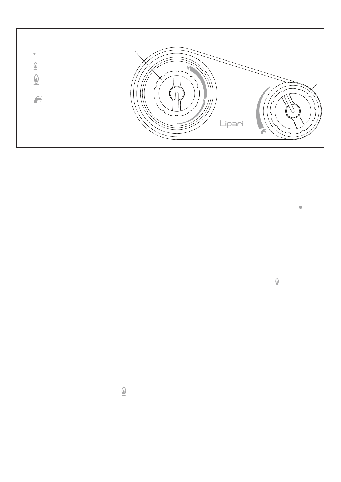
3.b Usage
Ensure that the gas tap and all water taps are switched off
- Turn on the Main gas supply tap or that of the gas tank if using
Liqueed Petroleum Gas (L.P.G.)
- Open the gas tap, not supplied with the device, placed immedia-
tely before the water heater on the gas input pipe
- Rotate knob A towards the large ame (ON ), during rotation,
when the small ame is reached it is necessary to press lightly
while turning until it reaches its destination.
- When hot water is requested, the device automatically turns on
the pilot ame, this lights the main burner.
- When the hot water request has terminated (turning the water
tap off) the burner automatically switches off, the device then
awaits another heating request.
If after 60 seconds it does not switch on, the ame detector inter-
rupts the ow of gas and blocks the device.
To reuse the device after it has been blocked, close the hot water
extraction tap and then reopen it to restart the sequence.
If the main burner accidentally switches off, the device will attempt
to turn it on again.
If within 60 seconds the device does not function it is blocked.
The device is built to function with normal water pressure; in addi-
tion a temperature selector B is also supplied.
Rotate the knob completely to the left to obtain the maximum water
output or completely to the right for the minimum water output.
The machine is switched off by rotating knob A to the ( OFF) po-
sition.
When the water heater is not used for long periods close the gas
supply tap or the LPG gas valve on the tank.
For the best operational results it is recommended to have a quali-
ed technician service the machine at least once a year.
Gas economizer
The device is equipped with a gas economizing device which is
used to choose the temperature of the water so it may be supplied
at the temperature necessary while saving gas.
The economizing device is activated by turning the knob A until it
reaches the picture of the small ame (MIN ). Using the econo-
mizer limits the amount of heating when the hot water usage is mo-
dest (water supplied is already warm or there is a reduced usage,
for example in summer).
DANGER OF FREEZING
If there is a possibility that the area where the device is stalled
could reach below 0°C, the device must be emptied of all water
contained.
A = Gas economizer on/off
off position
minimum gas level
maximum gas level
B = Water temperature selector
Fig. 25
A
B
3. OPERATION

13
4. MAINTENANCE
To maintain the machine at maximum efciency, have qualied per-
sonnel perform a maintenance check at least once a year.
Before cleaning or performing maintenance, opening or disassem-
bling the panels, switch off the device and turn off the gas supply.
Check the main burner and the pilot ame, the ignition electrode,
the safety valve and that there is no leakage. Check that there
is nothing obstructing the passages within the exchanger smoke
channel.
To clean the outside of the panels utilize a cloth with soap and
water.
Do not use solvents, powders or abrasive sponges.
Do not clean the device and/or its parts with ammable materials
(e.g. petrol, alcohol, diesel etc.).
4.a Removing the casing
To remove the outer casing follow the steps below:
- Remove the selector Knobs (A and B)
- Remove the screws (C)
- Shift the casing upwards to free it from the upper and lateral ho-
oks
- Shift the casing forwards
- To reinsert the casing, follow the above steps in reverse order
AB
Fig. 26
C

14
4.b Troubleshooting: problems and solutions
For the best functioning of the water heater, to prolong its lifetime and ensure that it is always safe, ensure that it is inspected at least once
a year by a trained professional. The trained professional is to perform the following maintenance operations:
- Remove any rust from the burner
- Remove any deposit on the glow plug by the electrode
- Clean the combustion tank
- Check the ignition, switching off and general functionality of the device
- Check that the gas and water tubes and connections are sealed
Warning: the owing repair instructions are only to be performed by qualied and authorized technicians.
PROBLEM CAUSE SOLUTIONS
There is no spark - Exhausted battery - Substitute
- Electrical cable of device is disconnected - Insert
- Electrical card is broken - Test, substitute
- There isn’t sufcient water pressure - Repair the device to guarantee pressure,
rotate the selector knob all the way to the
right
- The membrane is broken - Substitute
- The electrode is damaged - Substitute
The pilot does not switch on when
there is a spark
- Safety device broken - Substitute
- No gas supply - Open the gas tap
- Air in the gas tubes - Release gas
The burner does not switch off
when the water turns off
- Grime on the gas shutter - Test, clean
- Valve piston or stem is locked in open po-
sition
- Disassemble, clean and eventually substi-
tute
- Micro lever is locked in open position - Test
- If an LPG supply, check the gas pressure - Regulate and if necessary substitute the
tank pressure regulator
The exchanger blade becomes
dirty in a small amount of time
- Poor draught or dusty surroundings - Check the smoke channel efciency
- Yellow ame - Check the gas type and clean the burner
- Excess gas consumption - Check and regulate
There is a smell of gas - Due to the loss of gas in the tubes, check
the tubes and nd the leak
- Do not activate electric switches or any
object that produces sparks in local area
There is a smell of gas - It can be caused by obstruction in the ue
gas circuit
- Check the efciency of the smoke channel
and the ue gas conduit
- Excess gas consumption - Check and regulate

15
5. GENERAL TERMS OF WARRANTY
The Warranty is the one provided by the regulations and laws governing the sale of consumer goods in the country of purchase.
For further information contact the dealer/importer.
Warranty exclusions
The warranty is excluded with respect to damage, malfunctions and defects that may be detected on Fondital gas water heaters and
caused by:
a) Transport by third parties.
b) Negligence in the storage and handling of the product.
c) Inability to use the product and accessories, and failure to follow instructions and warnings outlined in the use and maintenance ma-
nual supplied.
d) Insufcient ow rate and defective gas, water and power supplies.
e) Tampering or work by personnel not authorised by the manufacturer.
f) Installation of the product in an unsuitable place (internal or external) and problems arising from incorrect or improper installation.
g) Inadequacy of ues and/or the ue gas venting pipe and combustion air intake, as well as use of components, ue pipes or heat
transfer uids that are not suitable for the type of products that are installed or are not Fondital original parts.
h) Storage in unprotected areas of construction sites.
i) Failure to empty the system or premature installation.
j) Corrosion of the system and formation of limescale build-up or other deposits arising from the supply water.
k) Failure to clean the system with suitable products whether it be new or old.
l) Force majeure due to particular weather events (e.g., earthquakes, oods, lightning, storms, excessive precipitation, etc.), as well as
res, vandalism, theft; stray currents and/or harmful effects due to atmospheric elements.
m) Use of inadequate fuel and/or in any case for reasons not depending on the manufacturer.
n) Forced or prolonged suspension of product operation.
Furthermore, the warranty is considered void in the following cases:
a) If the end user is not current with payments.
b) If the system is not installed in full compliance with regulations and laws, as well as the instructions and warnings published in the
installation, use and maintenance manual supplied with the product.
c) In case of skipped or inadequate periodic maintenance.
d) In case of use of non-original spare parts.
Furthermore, these operations are not covered by the warranty: plumbing, electrical, gas supply and ue connections, combustion
analysis, as well as activities and operations to access the product, like disassembling furnishings or covers, preparation of scaffolding,
use of platforms, cranes etc.
Moreover, the customer will bear all the expenses if service is required to rectify erroneous technical work, tampering, or, in any case,
damage to the product not attributable to manufacturing defects.

16
Fondital S.p.A.
25079 VOBARNO (Brescia) Italy - Via Cerreto, 40
Tel. +39 0365/878.31
Fax +39 0365/878.576
e-mail: [email protected]
www.fondital.com
The manufacturer reserves the right to modify his/her products
as deemed necessary, without altering the basic characteristics of
the products themselves.
U. Pubblicità Fondital IST 03 C 1079-01 Aprile 2017 (04/2017)
This manual suits for next models
1
Table of contents
Other Fondital Water Heater manuals


Popular Water Heater manuals by other brands

Sunsystem
Sunsystem HYG series Installation and operation manual

Eco-Smart
Eco-Smart ECO-6 installation instructions

AQUATECH
AQUATECH RAPID/X6 owner's manual

Glowworm
Glowworm Easicom 28 Instructions for use

TriangleTube
TriangleTube 30 Installation & maintenance manual

PVI
PVI Durawatt Polymer-Plated Storage Tank specification

Drazice
Drazice OKC 200 NTRR/SOL Operation and installation manual

Dux
Dux 2F136S owner's manual

Nibe
Nibe VVM 310 Service manual

Bradford White
Bradford White 238-16152-00F Installation and operating instruction manual

PVI
PVI NickelShield Tank Series Specifications

flamco
flamco 120 litres Installation, commissioning and maintenance instructions


