flamco 120 litres Guide
SUPASTOR
UNVENTED CYLINDERS
Installation, commissioning
and maintenance instructions
Direct and indirect enamelled c linders:
120, 150, 180, 210, 250 and 300 litres
Ref:Inst 5C/03
Important:
Please read these instructions carefull before proceeding
with installation. Failure to do so ma invalidate warrant .
Flamco UK Limited.
Unit 4,
St. Michael’s Road,
Lea Green Industrial Estate,
St. Helens
Merseyside WA9 4WZ.
Telephone: 01744 818100.
Fax: 01744 830400.
Email: [email protected]
www.flamco.co.uk
BS EN ISO 9001
Certificate No: FM 34109
R
E
G
I
S
T
E
R
E
D
QUALITY
MANAGEMENT
UKAS
APPROVED
12

WATER BYE-LAWS
Only approved materials, pipes and fittings that comply with water bye-laws should be used.
BUILDING REGULATIONS
The installation of an unvented hot water storage cylinder is regulated by Building Regulations G3. To meet the
requirements of the Regulation, installation of an unvented system should be undertaken by a ‘competent installer’.
IMPORTANT
It is important to note that it is a criminal offence to install an unvented hot water storage system without notifying
your Local Authority.
SUPASTOR DIRECT CYLINDER (Diagram A)
The Supastor direct cylinder, available in nominal capacities of 120 litres, 150 litres, 180 litres, 210 litres, 250 litres
and 300 litres, are supplied as:-
One large box containing -
The Supastor unit with factory fitted temperature and pressure relief valve and magnesium anode.
One small box containing -
The unvented kit which consists of a 12 litre expansion vessel, pressure reducing valve set at 3 bar with in-line
strainer, a safety group (expansion relief valve, tundish and single check valve) and two immersion heaters.
SUPASTOR INDIRECT CYLINDER (Diagram B)
The Supastor indirect cylinder, available in nominal capacities of 120 litres, 150 litres, 180 litres, 210 litres, 250 litres
and 300 litres, are supplied as:-
One large box containing -
The Supastor unit with factory fitted temperature and pressure relief valve, cylinder thermostat and magnesium
anode.
One small box containing -
The unvented kit which consists of a 12 litre expansion vessel, pressure reducing valve set at 3 bar with in-line
strainer, a safety group (expansion relief valve, tundish and single check valve), a 2-port motorised valve and one
immersion heater.
SUPASTOR UNVENTED CYLINDERS
Installation, commissioning and maintenance instructions
1. Hot water supply. 2. Immersion heater.
3. Mg anode. 4. Cold water inlet.
5. Temperature/pressure relief valve.
6. Steel cylinder, enamelled inside.
7. Polyurethane foam insulation.
1. Hot water supply. 2. Mg anode. 3. Thermostat.
4. Flow. 5. Immersion heater. 6. Return.
7. Cold water inlet. 8. Temperature/pressure relief valve (3/4”).
9. Steel cylinder, enamelled inside.
10. Polyurethane foam insulation.
10
9
8
7
6
5
4
3
2
1
4
3
2
1
2
7
6
5
Diagram A. Diagram B.
Supastor Direct C linder Supastor Indirect C linder
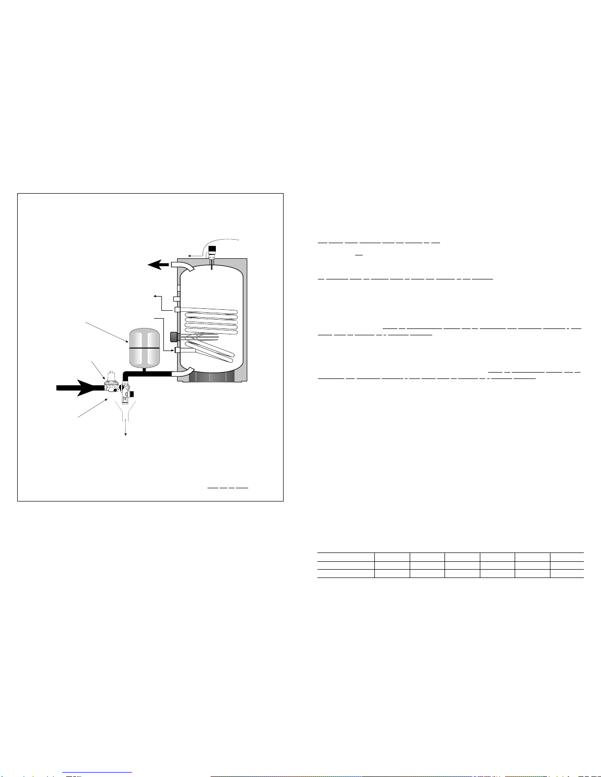
211
Expansion
vessel
To Drain
To Discharge
Safety
group
Cold
mains
in 6 bar expansion
relief valve
3 bar PRV
Hot water
supply
Schematic diagram of Supastor direct unvented hot water controls. Diagram I.
(As diagram C
on page 8).
THE CYLINDER
The cylinder must only be installed in the vertical position. The inlet pipe delivers cold water to the bottom of the
cylinder. An unvented kit is provided which comprises of a Flexcon expansion vessel (to accommodate any increase
in water volume), pressure reducing valve and safety group (expansion relief valve, tundish and single check valve.
IMPORTANT - the discharge from the expansion relief valve must be made and piped away safely.
COLD WATER SUPPLY
The mains water pressure must not exceed 12 bar.
As hot and cold water are both drawn off the same supply, it is important to ensure that the cold water feed is capable
of supplying the full demand. Please identify all the connection ports before making any connections to the cylinder
(See diagrams A and B on page 2).
For maintenance, position an isolating valve between the cold water supply and the cylinder.
All pipework must be flushed clean to avoid an damage to the controls.
INDIRECT CYLINDERS
Indirect cylinders are supplied with a 2-port motorised valve in accordance with Water Board regulations G17.1(b),
and have dual thermostatic controls.
A separate cylinder thermostat is supplied to control the indirect circuit via the motorised valve. In accordance with
Water Bye-Law G20.6, and integral thermal cut-out stat is incorporated within the cylinder stat housing, and is wired
through to the heat source, and operates if the water temperature rises too high. Should the thermal cut-out activate it
can only be re-set manually. Under no circumstances should this be b -passed. The activation indicates afault
which must be rectified b aqualified engineer.Refer to diagram E on page 8 for recommended wiring details.
IMMERSION HEATERS
The cylinder immersion heater(s) are connected through a thermostat which pre-sets the operating temperature. The
required operating temperature can be adjusted at the head of the thermostat. In accordance with Water Bye-Law
G20.6 the immersion heater is pre-wired through a thermal cut-out stat, which operates if the water temperature rises
too high. Should the thermal cut-out activate it can only be re-set manually. Under no circumstance should this be
b -passed. The activation indicates afault which must be rectified b aqualified engineer.Refer to diagram G
on page 9.
FITTING THE IMMERSION HEATER(S)
The electrical installation must be in accordance with the current I.E.E. wiring regulations.
Care must be taken not to cross thread the immersion heater(s) when fitting.
A 220/240V mains supply fused 13 amp is required. Heat resistant cable, round 3 or 4 core 2.5mm2(to BS.6141.
table 8) must be used to connect the electrical supply through the Economy 7 time control switch as shown in
diagram G on page 9.
If the Economy 7 system is not used then a separate 13 amp supply to each element will be required through a
double pole fused isolating switch having a contact gap of at least 3mm on each pole. Make the connection(s) to the
immersion heater(s).
The thermostat(s) on the immersion heater(s) should be adjusted to trip at 60OC. This is the ideal temperature to
prolong the element’s life in hard water areas. Scale on the sheath builds up more rapidly at temperature above 60OC
causing the element to overheat and premature failure could occur. Higher temperatures without additional controls
would result in scalding.
WARNING: THE APPLIANCE MUST BE EARTHED
The earth continuity conductor of the electrical installation must be effectively connected to all exposed parts of other
appliances and services in the room where the unvented cylinder is housed - conformity with the I.E.E. regulations.
SITING THE UNVENTED CYLINDER
As the unvented cylinder is connected directly to the mains cold water supply, the siting is optional. However, for easy
maintenance leave free space for access to the electrical components (immersion heater(s) and anodes). Care
should be taken to ensure the support of the load bearing strength as per the table below.
Supastor Size
Weight full Direct unit
Weight full Indirect unit
300 litre
356 kg
376 kg
250 litre
305 kg
322 kg
210 litre
255 kg
272 kg
180 litre
223 kg
234 kg
150 litre
192 kg
203 kg
120 litre
173 kg
181 kg
310
Expansion
vessel
To Drain
To Discharge
Safety
group
Cold
mains
in 6 bar expansion
relief valve
3 bar PRV
Heating
flow
Heating
return
Hot water
supply
Schematic diagram of Supastor Indirect unvented hot water controls. Diagram H.
NOTE:
All components must be fitted.
If the system is to be fitted with a 3 port valve, the 2 port valve supplied by Flamco must still be fitted.
(As diagram C
on page 8).
TEMPERATURE AND PRESSURE RELIEF VALVE
The factory fitted temperature and pressure relief valve, sited on top of the unvented cylinder, is a safet device to
back-up and support the thermostat(s) and thermal cut-out(s). It operates when either excess pressure or excess
temperature is sensed. When operated, hot water will be discharged so care must always be taken. The discharge is
connected to a tundish and drain.
Note: The temperature and pressure relief valve must not be removed under an circumstance. Such action
will invalidate the warrant .
DISCHARGE PIPEWORK FROM THE TEMPERATURE AND PRESSURE RELIEF VALVE
The tundish must be vertical and fitted within 300mm of the temperature and pressure relief valve and must be
located near the unvented cylinder. The tundish must also be in a position visible to the occupants, and positioned
away from electrical devices. The discharge pipe from the tundish should be metal and should terminate in a safe
place where there is no risk to persons in the vicinity of the discharge.
Refer to diagram C on page 8.
ALL INSTALLATIONS MUST CONFORM TO BUILDING REGULATIONS G3.
COMMISSIONING
Check for obvious signs of damage to the unvented cylinder and associated controls.
Do not switch the immersion heater(s) or fire the boiler until the unvented c linder is full of water.
1. Open all outlet taps.
2. Turn on mains water supply and allow the unvented cylinder to fill.
3. Close taps in turn after having purged the system of air.
4. Check for leaks around the controls and immersion heater(s). Repeat this check again after the unit has
heated up.
5. Check that no water is passing to discharge through the temperature and pressure relief valve and the expansion
relief valve.
6. Test the operation of the temperature and pressure relief valve and the expansion relief valve by lifting/turning the
manually operated test cap and ensure that water flows through freely and safely to waste.
7. Check that the discharge pipe is plumbed so that it falls continuously and that no taps, valves or other shut-off
devices are installed in the pipe.
8. Check that all thermostats are set to 60OC.
9. DIRECT UNITS: Switch on immersion heater(s) and allow the unit to heat up. Check the operation of the
thermostat(s).
10. INDIRECT UNITS: Fill the indirect (primary) circuit, following the boiler instructions. Switch on the boiler, ensuring
that the programmer is to domestic hot water. Allow the unit to heat up and check the operation of the cylinder
thermostat on the motorised valve.
11. Demonstrate the operation of the unit to the occupier, including the temperature and pressure relief valve and
what to do if it operates.
12. Give this manual to the occupier to retain for future reference and make the occupier aware that periodic checks
of the equipment are essential for safety.
13. Complete the ‘Supastor Service History Book’provided and leave with the occupier.
MAINTENANCE OF THE MAGNESIUM ANODE
The installer should check the magnesium anti-corrosion anode after two years (consult the label on the face of the
unit for correct location). If the heating element is heavily coated with scale we recommend descaling at the time of
this inspection. If the anode is still operational and is not replaced then further annual checks are required. If the
anode is replaced then it does not need re-checking for a further two years.
EXAMINE THE ANODE AND REPLACE IF THE DIAMETER IS LESS THAN 15mm.
Removal of Anode:
1. Close the mains supply service valve.
2. Open hot water taps.
3. Ensure the cylinder is empty.
4. The anode can now be removed.
5. Descale the immersion heater(s) and remove any lime deposit from the cylinder and heating element.
Replace in reverse order.
(continued overleaf
4 9
L
N
L
N
L
N
L
N
Day Element
3kW 220/240V
Pre-wired
Pre-wired
Night Element
3kW 220/240V
Economy 7
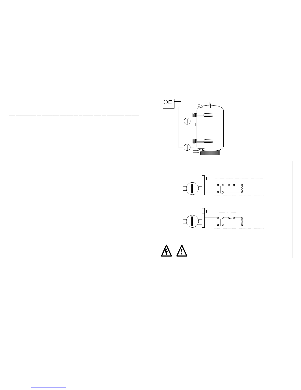
TOP ELEMENT
BOTTOM ELEMENT
Thermal
cut-out Thermo
stat
Thermal
cut-out Thermo
stat
Element
Isolating
switch
Isolating
switch
Bottom Element
(Night Store)
Economy 7
controller
Diagram F.
Recommended Direct System
Economy 7
Recommended wiring for Supastor Direct Cylinder - Economy 7
Electrical installation must be carried out by a competent person.
Isolate unit before removing any covers.
Wire using 1.5mm2flexible cable, 85OC rubber insulated HOFR sheathed, complying with BS.6141
Table 8. It must be fully earthed and wired through a double pole isolating switch.
Diagram G.
Check the controls:
1. Check and clean the strainer before refilling the system.
2. Check the pressure in the expansion vessel and top up as necessary.
3. Check the temperature and pressure relief valve manually by turning the top cap.
4. Check the expansion relief valve manually by turning the top cap.
5. Check discharge pipes for both the temperature and pressure relief valve and the expansion relief valve for
obstructions.
SUPASTOR ANODE OPTION
An option is available to replace the magnesium anode with a Flamco impressed current anode.
The installation should be carried out as follows:
Remove the magnesium anode fro the Supastor cylinder, using a 1.1/4”x 3/4”bush insert the Flamco impressed
current anode.
Important:
The Flamco impressed current anode must be earth bonded to the cylinder.
To ensure the correct functioning of the Flamco ‘ICA’the following information relating to safety must be strictly
observed.
1. To avoid annoying gas accumulation within the cylinder, it is essential that the storage water must be drawn from
the cylinder once a month.
2. Never unplug the ‘ICA’when the cylinder is storing water as this will disable the anode protection.
3. The potentiostat is housed in a protective casing and is pre-wired for ease of installation.
4. Only use the original connection leads.
5. Do not under any circumstance alter the length of the connection leads.
6. Site the potentiostat adjacent to the Supastor unvented cylinder.
7. take a 220/240V supply to the Flamco ‘ICA’potentiostat.
The Flamco ‘ICA’connecting calbes are identified as follows:
Black cable = Earth.
Black and white cable = Flamco ‘ICA’connection.
58
Temperature
and pressure
relief valve
Metal dischage pipe
from temperature and
pressure relief valve
to tundish
Tundish
Metal dischage pipe
from tundish with
continuous fall. Discharge
below fixed
grating
Trapped
gulley
500mm
max. 300mm
max.
300mm
min.
L
N
L
N
L
N
L
N
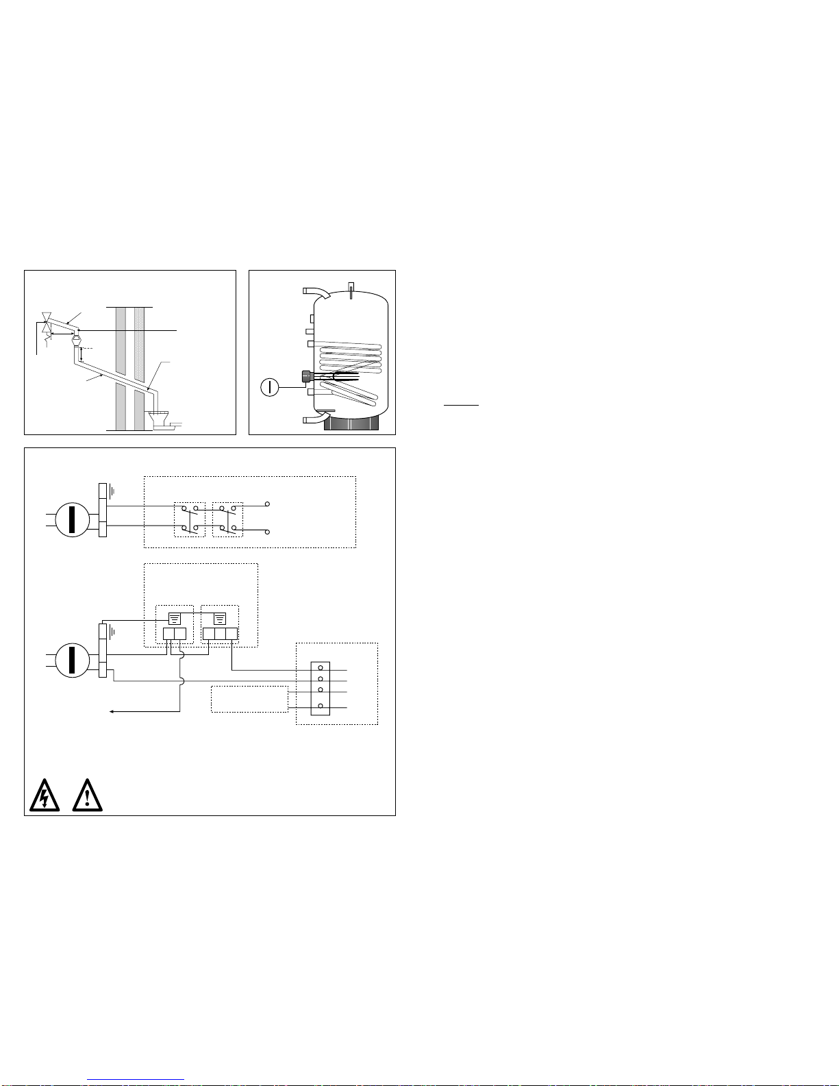
Immersion heater
Single 3Kw element
Pre-wired
Brown
Blue
Orange
Grey
Motorised valve
Optional connections
See Motorised valve
instructions
Live to boiler
C1C21
Safety
Limiter Thermostat
Thermostat and
Safety Limiter
Suggested way of terminating discharge pipe
Diagram C.
Recommended wiring for Supastor Indirect Cylinder
Electrical installation must be carried out by a competent person.
Isolate unit before removing any covers.
Wire using 1.5mm2flexible cable, 85OC rubber insulated HOFR sheathed, complying with BS.6141
Table 8. It must be fully earthed and wired through a double pole isolating switch.
Diagram E.
Element
Isolating
switch
Diagram D.
Recommended
Indirect System
1" pipe
3/4" pipe

FAULT FINDING
FAULT POSSIBLE CAUSES REMEDY
No hot water flow. 1. Mains cold water supply Check and open isolating and/or stop valve.
shut-off. If no water flow check with local water authority.
2. Line strainer blocked. Turn off mains water supply, remove and clean
line strainer.
3. Cold water safety group Check direction of flow arrows on the valve. Refit in
fitted incorrectly. the correct position if necessary.
Reduced flow rate. 1. Low mains water pressure. Check pressure, xonsult local water authority
if necessary.
2. Strainer partially blocked. Turn off mains water supply, remove and clean
strainer.
3. Size of service pipe too small. Pipe size should be increased.
Water from hot 1. Direct immersion heater is Check immersion heater, switch on if necessary.
taps is cold. not switched on.
2. Direct thermal cut-out has Test thermostat operation and wiring, if faulty
operated. correct or replace. Re-set cut-out.
3. Boiler programmer set to Check switch on domestic hot water if necessary.
central heating only.
(Indirect model).
4. Boiler is not functioning. Check boiler operation, if fault suspected consult
(Indirect model). manufacturer’s instructions.
5. Indirect thermal cut-out has Test thermostat operation and wiring, if faulty correct
operated. /replace. Re-set cut-out.
6. Motorised valve jammed or Check wiring and operation of motorised valve,
not wired correctly. if faulty correct/replace as necessary.
(Indirect model).
Discharge from 1. Pressure above 7 bar, Shut down boiler or immersion heater. Check
pressure and failure of pressure reducing pressure reducing valve and thermal controls.
temperature valve. Temperature above Replace if necessary.
relief valve. 90OC, failure of thermal
control.
Discharge from 1. Pressure reducing valve Check pressure from valve. Replace if over 3.5 bar.
expansion relief faulty.
valve. 2. When heater is heating, Check charge in vessel. Re-charge vessel to
faulty expansion vessel 3.5 bar or replace if necessary.
or lost charge.
6 7
GUARANTEE
Flamco UK Limited guarantee that should this water heater prove to be defective by reason of faulty manufacture
during the periods stated below, will replace the defective parts or product free of charge on the condition that:-
The appliance has been correctly installed by a competent installer and used only on the
supply voltage stamped on the rating plate.
The appliance has been used and maintained in accordance with these instructions and
has not been tampered with or otherwise subjected to misuse, neglect or accident.
The appliance has not been taken apart, modified or repaired except by a qualified
service engineer.
Evidence of the date of purchase, in the form of an invoice, receipt or hire purchase
documents, must be included with the appliance when returned under guarantee.
The guarantee will be applicable from the date of purchase or commencement of hire
purchase for the following periods:-
12 months on electrical parts and components.
3 years on the cylinder tank.
Flamco UK Limited
This manual suits for next models
6
Table of contents
Other flamco Water Heater manuals


Popular Water Heater manuals by other brands

Grainfather
Grainfather EZZZ9169 instructions
 Use & care manual")
Waiwela
Waiwela PH2-20R DVSN (Natural Gas) Use & care manual

Quooker
Quooker PRO7 installation guide
 user manual")
Haier
Haier Little Sea-ox FCD-JTHC80A-III (E) user manual

Siemens
Siemens DG10016R2 Assembly and operating instructions

Ariston
Ariston ABS DACHA R 50 V quick start

Honeywell
Honeywell WV4262B installation instructions

Bradley
Bradley S19-690 Installation

Midea
Midea MWH-38Q instruction manual

RBI
RBI FUTERA XLF Series Installation and operation instructions

Pundmann
Pundmann THERM-9L Assembly, installation and operating instructions

STIEBEL ELTRON
STIEBEL ELTRON MINI 2-1 Operation and installation


